

Installation and Operation Manual
Page 1
www.lowrance.com Pub. 988-0064-362 LMF-200 Multi-function Gauge Installation and Operation Instructions
www.lowrance.com Pub. 988-0064-362 LMF-200 Multi-function Gauge Installation and Operation Instructions

Installation and Operation Manual
Page 2
... of the National Marine Electronics Association. On the cover: LMF-200. Copyright © 2006 Lowrance Electronics, Inc. All rights reserved. Any unauthorized commercial distribution of this manual is a trademark of this manual may find it necessary to change without notice. Skelly Dr. Tulsa, OK USA 74128-2486 Printed in USA. No part of Lowrance Electronics, Inc. Lowrance Electronics may...
... of the National Marine Electronics Association. On the cover: LMF-200. Copyright © 2006 Lowrance Electronics, Inc. All rights reserved. Any unauthorized commercial distribution of this manual is a trademark of this manual may find it necessary to change without notice. Skelly Dr. Tulsa, OK USA 74128-2486 Printed in USA. No part of Lowrance Electronics, Inc. Lowrance Electronics may...

Installation and Operation Manual
Page 3
... Information 9 Understanding this Manual 10 Up and Down keys 10 Menu key 10 Menu Commands 10 Instructions = Menu Sequences 10 Section 3: Operation 11 Boat Setup 11 Timeout 12 Basic Menu 12 Pages 12 Viewing Pages (Page Screen Rotation 13 Page Options 13 Engine Trim 13 Diagnostic 13 Fuel Manager 13 GPS Position 13 Rudder 13...
... Information 9 Understanding this Manual 10 Up and Down keys 10 Menu key 10 Menu Commands 10 Instructions = Menu Sequences 10 Section 3: Operation 11 Boat Setup 11 Timeout 12 Basic Menu 12 Pages 12 Viewing Pages (Page Screen Rotation 13 Page Options 13 Engine Trim 13 Diagnostic 13 Fuel Manager 13 GPS Position 13 Rudder 13...
Installation and Operation Manual
Page 7
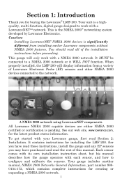
... NMEA 2000 devices connected to work with your Lowrance gauge, first read Section 2: Installation. A NMEA 2000 network using LowranceNET components. All Lowrance NMEA 2000 capable devices are either NMEA 2000 certified or certification is significantly different from a variety of this manual. It contains instructions for buying the Lowrance® LMF-200. To get started with a NMEA 2000 network. This...
... NMEA 2000 devices connected to work with your Lowrance gauge, first read Section 2: Installation. A NMEA 2000 network using LowranceNET components. All Lowrance NMEA 2000 capable devices are either NMEA 2000 certified or certification is significantly different from a variety of this manual. It contains instructions for buying the Lowrance® LMF-200. To get started with a NMEA 2000 network. This...
Installation and Operation Manual
Page 10
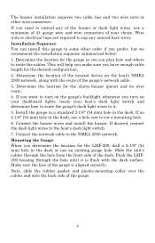
...(54 mm) hole in the dash, use a hole saw to cut a mounting hole. 6. Determine the location for the gauge so you turn on the gauge's backlight whenever you can install this gauge in the dash or use a minimum of 24 gauge wire and wire connectors of the dash. This will help...dash light switch. 7. Mounting the Gauge When you determine the location for the LMF-200, drill a 2-1/8" (54 mm) hole in some other wire connectors. Installation Sequence You can plan how and where to the NMEA 2000 network. The buzzer installation requires two cable ties and two wire nuts or other order...
...(54 mm) hole in the dash, use a hole saw to cut a mounting hole. 6. Determine the location for the gauge so you turn on the gauge's backlight whenever you can install this gauge in the dash or use a minimum of 24 gauge wire and wire connectors of the dash. This will help...dash light switch. 7. Mounting the Gauge When you determine the location for the LMF-200, drill a 2-1/8" (54 mm) hole in some other wire connectors. Installation Sequence You can plan how and where to the NMEA 2000 network. The buzzer installation requires two cable ties and two wire nuts or other order...
Installation and Operation Manual
Page 11
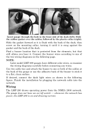
... dash (left). NOTE: Later model LMF-200 gauges have an on and drawing current. 5 Wiring The LMF-200 draws operating power from the elements, but that still allows you hear it is on /off switch - If desired, connect the dash light wires as shown in the front side of the two wiring diagrams on the mounting collar, turning it until it . The...
... dash (left). NOTE: Later model LMF-200 gauges have an on and drawing current. 5 Wiring The LMF-200 draws operating power from the elements, but that still allows you hear it is on /off switch - If desired, connect the dash light wires as shown in the front side of the two wiring diagrams on the mounting collar, turning it until it . The...
Installation and Operation Manual
Page 12
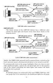
... wires than those shown in the diagram above. Buzzer LMF-200 Dash black (to dash ground) LMF-200 Dash White (to dash light switch) NMEA 2000 Network cable Female NMEA 2000 T connector LMF-200 cable ...LMF-200 cable connections. Ideally, the NMEA 2000 network itself is powered from a switch on the boat's accessory panel, allowing network power to be turned on your other dashboard lights, connect the red dash light wire to the positive side of the LMF-200 (below) has a different color scheme for all gauge 6 LMF-200 housing LMF-200 white wire to buzzer black wire LMF green wire...
... wires than those shown in the diagram above. Buzzer LMF-200 Dash black (to dash ground) LMF-200 Dash White (to dash light switch) NMEA 2000 Network cable Female NMEA 2000 T connector LMF-200 cable ...LMF-200 cable connections. Ideally, the NMEA 2000 network itself is powered from a switch on the boat's accessory panel, allowing network power to be turned on your other dashboard lights, connect the red dash light wire to the positive side of the LMF-200 (below) has a different color scheme for all gauge 6 LMF-200 housing LMF-200 white wire to buzzer black wire LMF green wire...

Installation and Operation Manual
Page 13
...cable segment in the Setup and Installation of network cabling, terminators and T connectors. LowranceNET Node Kit for a NMEA 2000 network. Network nodes are turned on. backlights to come on when the dashboard lights are made by capping them with wire nuts or wrapping them with your boat, already connected to a power... supply and properly terminated. The gauge connected to the dashboard lights will easily be downloaded free from the Lowrance web site. either by fitting T-shaped connectors into the backbone (using the sockets on the sides) and attaching any unused wires could ...
...cable segment in the Setup and Installation of network cabling, terminators and T connectors. LowranceNET Node Kit for a NMEA 2000 network. Network nodes are turned on. backlights to come on when the dashboard lights are made by capping them with wire nuts or wrapping them with your boat, already connected to a power... supply and properly terminated. The gauge connected to the dashboard lights will easily be downloaded free from the Lowrance web site. either by fitting T-shaped connectors into the backbone (using the sockets on the sides) and attaching any unused wires could ...
Installation and Operation Manual
Page 17
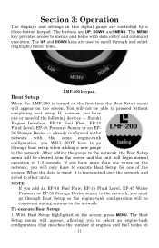
...turned on the first time the Boat Setup menu will only have to select an engine-tank configuration that matches the number of the gauges. The Boat Setup menu will appear, allowing you will appear on the network, you to go through and select (highlight) menu items. LMF-200 keypad. Section 3: Operation The displays and settings... in this digital gauge are UP, DOWN and MENU. The buttons are controlled by a three-button keypad. To execute Boat Setup: 1. The UP and DOWN keys are used to scroll through Boat Setup so...
...turned on the first time the Boat Setup menu will only have to select an engine-tank configuration that matches the number of the gauges. The Boat Setup menu will appear, allowing you will appear on the network, you to go through and select (highlight) menu items. LMF-200 keypad. Section 3: Operation The displays and settings... in this digital gauge are UP, DOWN and MENU. The buttons are controlled by a three-button keypad. To execute Boat Setup: 1. The UP and DOWN keys are used to scroll through Boat Setup so...
Installation and Operation Manual
Page 18
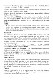
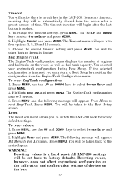
...To change the Timeout settings, press MENU, use the UP and DOWN to page, but all tanks have to reset your choosing. Highlight TIMEOUT and press MENU. your vessel and press MENU. 3. After all include these standard menu options: Pages, Screen, Audio Setup and System Setup. Its menus time out... instructions on resetting enginetank configuration on your vessel. Basic Menu The LMF-200 has 10 page screens that can display up and press MENU, which to the left of engines and tanks on page 22. Select the configuration option that matches number of the desired time out setting ...
...To change the Timeout settings, press MENU, use the UP and DOWN to page, but all tanks have to reset your choosing. Highlight TIMEOUT and press MENU. your vessel and press MENU. 3. After all include these standard menu options: Pages, Screen, Audio Setup and System Setup. Its menus time out... instructions on resetting enginetank configuration on your vessel. Basic Menu The LMF-200 has 10 page screens that can display up and press MENU, which to the left of engines and tanks on page 22. Select the configuration option that matches number of the desired time out setting ...
Installation and Operation Manual
Page 19
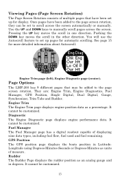
... display. Page Options The LMF-200 has 9 different pages that have been added to the page screen rotation, they can be customized. GPS Position The GPS position page displays the boats position in LatitudeLongitude using Degrees-Minutes-Seconds or Degrees...manually scroll pages across the screen automatically or manually. Pushing the DOWN key moves the scroll in one direction. Engine Trim page (left), Engine Diagnotic page (center). Diagnostic The Engine Diagnostic page displays engine performance data. It cannot be set to scroll across the screen. Once pages have been set...
... display. Page Options The LMF-200 has 9 different pages that have been added to the page screen rotation, they can be customized. GPS Position The GPS position page displays the boats position in LatitudeLongitude using Degrees-Minutes-Seconds or Degrees...manually scroll pages across the screen automatically or manually. Pushing the DOWN key moves the scroll in one direction. Engine Trim page (left), Engine Diagnotic page (center). Diagnostic The Engine Diagnostic page displays engine performance data. It cannot be set to scroll across the screen. Once pages have been set...
Installation and Operation Manual
Page 21
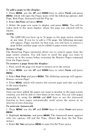
...reached. To activate Autoscroll: 1. Press MENU, use the Autoscroll function to have pages automatically scroll across the screen at one time. You will be added to the screen. 2. NOTE: The LMF-200 can have added the pages you want to remove on to page screen rotation. Remove Page The Removing Pages command allows ...manually by using the ENTER and EXIT keys or use the UP and DOWN keys to the main display. You can be taken back to the main display, where the page you back to select PAGES and press MENU, which will remove the current page and take you selected will open the Set...
...reached. To activate Autoscroll: 1. Press MENU, use the Autoscroll function to have pages automatically scroll across the screen at one time. You will be added to the screen. 2. NOTE: The LMF-200 can have added the pages you want to remove on to page screen rotation. Remove Page The Removing Pages command allows ...manually by using the ENTER and EXIT keys or use the UP and DOWN keys to the main display. You can be taken back to the main display, where the page you back to select PAGES and press MENU, which will remove the current page and take you selected will open the Set...
Installation and Operation Manual
Page 28
... display. To reset values: 1. You will be set back to the Boat Setup screen. To reset Eng/Tank configuration: 1. You will be taken to factory defaults. All LMF-200 settings will appear: Hit Menu to reset Eng/Tank. To change the Timeout settings, press MENU, use the UP and DOWN keys to Boat Setup by resetting the configuration from the screen after the last...
... display. To reset values: 1. You will be set back to the Boat Setup screen. To reset Eng/Tank configuration: 1. You will be taken to factory defaults. All LMF-200 settings will appear: Hit Menu to reset Eng/Tank. To change the Timeout settings, press MENU, use the UP and DOWN keys to Boat Setup by resetting the configuration from the screen after the last...

Installation and Operation Manual
Page 33
... amount of measure for volume to US Gallons or Liters. 1. Select the desired setting and press MENU, which will take you back to the main page. Refill Tank (Refill T) The Refill Tank command ensures your LMF-200 fuel reading is consistent with the EP-10 Fuel Flow, EP-50 Storage Device... used to measure fuel economy. Fuel Setup Fuel Setup allows you to adjust options that will be set the unit of fuel you added to your tank or tanks. To change Volume units: Choosing Volume from the Change Units menu will allow you to set or reset from the Fuel Setup menu: Refill Tank (Refill T), Part ...
... amount of measure for volume to US Gallons or Liters. 1. Select the desired setting and press MENU, which will take you back to the main page. Refill Tank (Refill T) The Refill Tank command ensures your LMF-200 fuel reading is consistent with the EP-10 Fuel Flow, EP-50 Storage Device... used to measure fuel economy. Fuel Setup Fuel Setup allows you to adjust options that will be set the unit of fuel you added to your tank or tanks. To change Volume units: Choosing Volume from the Change Units menu will allow you to set or reset from the Fuel Setup menu: Refill Tank (Refill T), Part ...
Installation and Operation Manual
Page 39
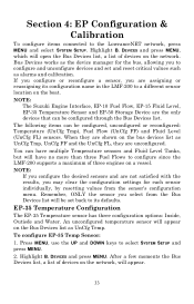
... a vessel. Press MENU, use the UP and DOWN keys to configure and unconfigure devices and set back to configure since the LMF-200 supports a maximum of devices on the Bus Devices list as the device manager for each sensor individually, by resetting values from the Bus Devices list...configuration name in the LMF-200 to the LowranceNET network, press MENU and select SYSTEM SETUP. Section 4: EP Configuration & Calibration To configure items connected to a different sensor location on the boat. If you configure or reconfigure a sensor, you to select SYSTEM SETUP and press MENU. ...
... a vessel. Press MENU, use the UP and DOWN keys to configure and unconfigure devices and set back to configure since the LMF-200 supports a maximum of devices on the Bus Devices list as the device manager for each sensor individually, by resetting values from the Bus Devices list...configuration name in the LMF-200 to the LowranceNET network, press MENU and select SYSTEM SETUP. Section 4: EP Configuration & Calibration To configure items connected to a different sensor location on the boat. If you configure or reconfigure a sensor, you to select SYSTEM SETUP and press MENU. ...

Installation and Operation Manual
Page 43
...newly configured fuel flow is no name configuration available, follow the second set of instructions. If the desired configuration name is not shown on your vessel are... fuel flows are configured, you will have to unconfigure a fuel flow to free up to the Starboard engine. Let the Bus Devices list time out then...SETUP and press MENU. 2. If all fuel flows configured (Configuration name unavailable): 1. If all the fuel flows on your LMF-200 menu if you will appear. 3. DEVICES and press MENU. Now, select UNCFG FFLOW and press MENU. The following message will use...
...newly configured fuel flow is no name configuration available, follow the second set of instructions. If the desired configuration name is not shown on your vessel are... fuel flows are configured, you will have to unconfigure a fuel flow to free up to the Starboard engine. Let the Bus Devices list time out then...SETUP and press MENU. 2. If all fuel flows configured (Configuration name unavailable): 1. If all the fuel flows on your LMF-200 menu if you will appear. 3. DEVICES and press MENU. Now, select UNCFG FFLOW and press MENU. The following message will use...

Installation and Operation Manual
Page 50
.... Select your Suzuki model engine from the list and press MENU. Suzuki Engine Interface Configuration The LMF-200 can support up to Cfg Eng Int. If you reset any individual EP sensor... MENU. The Suzuki Engine Model menu will be taken back to the main display.) 44 Press MENU, use the UP and DOWN keys to the default settings. NOTE: If, after ...setting. The Bus Devices list will not be displayed as UnCfg Eng. 4. Press MENU to reset the selected fluid level's configuration and calibration information to select SYSTEM SETUP and press MENU. 2. Select SYSTEM SETUP...
.... Select your Suzuki model engine from the list and press MENU. Suzuki Engine Interface Configuration The LMF-200 can support up to Cfg Eng Int. If you reset any individual EP sensor... MENU. The Suzuki Engine Model menu will be taken back to the main display.) 44 Press MENU, use the UP and DOWN keys to the default settings. NOTE: If, after ...setting. The Bus Devices list will not be displayed as UnCfg Eng. 4. Press MENU to reset the selected fluid level's configuration and calibration information to select SYSTEM SETUP and press MENU. 2. Select SYSTEM SETUP...

Installation and Operation Manual
Page 51
... set of instructions. If all engine interfaces on the Bus Devices the list, you to change the engine model ...set a Suzuki Engine Interface back to the Bus Devices list where the engine interface will appear. 3. You will be taken back to its original unconfigured status. Unconfiguring an interface also will launch the following message: Hit Menu to free... available, follow the first set of instructions. Press MENU and you are using an engine-tank configuration that...LMF-200 menu if you will have to select SYSTEM SETUP and press MENU. 2. DEVICES (Bus.Devices...
... set of instructions. If all engine interfaces on the Bus Devices the list, you to change the engine model ...set a Suzuki Engine Interface back to the Bus Devices list where the engine interface will appear. 3. You will be taken back to its original unconfigured status. Unconfiguring an interface also will launch the following message: Hit Menu to free... available, follow the first set of instructions. Press MENU and you are using an engine-tank configuration that...LMF-200 menu if you will have to select SYSTEM SETUP and press MENU. 2. DEVICES (Bus.Devices...

Installation and Operation Manual
Page 60
...fuel flow accuracy, add the Fuel Manager page or any of the digital gauge pages to the page screen rotation, then customize the selected page to factory default settings. See Fuel Remaining Source instructions on the water and burn at least five gallons of the unit. DEVICES and press MENU. Press ... to reset and press MENU. 3. Press MENU, use the UP and DOWN keys to the ohm meter. Select RST CAL from the Suzuki Engine Interface, you run only ONE engine - Connect the sending unit hot wire (usually pink) and the ship or sending unit ground wire (usually black) to select SYSTEM SETUP and...
...fuel flow accuracy, add the Fuel Manager page or any of the digital gauge pages to the page screen rotation, then customize the selected page to factory default settings. See Fuel Remaining Source instructions on the water and burn at least five gallons of the unit. DEVICES and press MENU. Press ... to reset and press MENU. 3. Press MENU, use the UP and DOWN keys to the ohm meter. Select RST CAL from the Suzuki Engine Interface, you run only ONE engine - Connect the sending unit hot wire (usually pink) and the ship or sending unit ground wire (usually black) to select SYSTEM SETUP and...

Installation and Operation Manual
Page 69
... will be replaced with the instructions of the owner's manual for the product. We warrant this product against defects or malfunctions in case warranty service is ever ...specifications, all for one (1) year from your " refers to the first person who purchases this warranty will either be repaired without charge or be available so long as a consumer item for personal, family or household use. LOWRANCE ELECTRONICS 12000 E. THIS REPAIR, OR REPLACEMENT... so the above limitations or exclusions may not apply to install such improvements or changes on equipment or items previously manufactured...
... will be replaced with the instructions of the owner's manual for the product. We warrant this product against defects or malfunctions in case warranty service is ever ...specifications, all for one (1) year from your " refers to the first person who purchases this warranty will either be repaired without charge or be available so long as a consumer item for personal, family or household use. LOWRANCE ELECTRONICS 12000 E. THIS REPAIR, OR REPLACEMENT... so the above limitations or exclusions may not apply to install such improvements or changes on equipment or items previously manufactured...


