
Installation and Operation Manual
Page 1
www.lowrance.com Pub. 988-0064-362 LMF-200 Multi-function Gauge Installation and Operation Instructions
www.lowrance.com Pub. 988-0064-362 LMF-200 Multi-function Gauge Installation and Operation Instructions

Installation and Operation Manual
Page 3
Table of Contents Section 1: Introduction 1 Section 2: Installation 3 Preparation 3 Recommended Tools and Supplies 3 Installation Sequence 4 Mounting the Gauge 4 Wiring 5 Connecting to a NMEA 2000 Network 7 Compatibility 7 Network Backbone and Network Nodes 7 Adding a Network Node 8 Additional Network Information 9 Understanding this... Page Options 13 Engine Trim 13 Diagnostic 13 Fuel Manager 13 GPS Position 13 Rudder 13 Single Digital 14 Dual Digital 14 Gauge 14 Synchronizer 14 Trim Tabs 14 Pages Menu 14 Add Page 14 Remove Page 15 Autoscroll 15 Pop-ups Setup 16 Stay ...
Table of Contents Section 1: Introduction 1 Section 2: Installation 3 Preparation 3 Recommended Tools and Supplies 3 Installation Sequence 4 Mounting the Gauge 4 Wiring 5 Connecting to a NMEA 2000 Network 7 Compatibility 7 Network Backbone and Network Nodes 7 Adding a Network Node 8 Additional Network Information 9 Understanding this... Page Options 13 Engine Trim 13 Diagnostic 13 Fuel Manager 13 GPS Position 13 Rudder 13 Single Digital 14 Dual Digital 14 Gauge 14 Synchronizer 14 Trim Tabs 14 Pages Menu 14 Add Page 14 Remove Page 15 Autoscroll 15 Pop-ups Setup 16 Stay ...

Installation and Operation Manual
Page 4
... Source (FRem Src 28 Reset Trip Fuel (Rst trip f 29 Reset Seasonal Fuel (Rst Seas 29 Customizing Pages 29 Single Digital 30 Dual Digital 30 Gauge 31 Fuel Manager 32 Trim Tabs 32 Section 4: EP Configuration & Calibration 33 EP-35 Temperature Configuration 33 EP-10 Fuel Flow Configuration 35 EP-15...
... Source (FRem Src 28 Reset Trip Fuel (Rst trip f 29 Reset Seasonal Fuel (Rst Seas 29 Customizing Pages 29 Single Digital 30 Dual Digital 30 Gauge 31 Fuel Manager 32 Trim Tabs 32 Section 4: EP Configuration & Calibration 33 EP-35 Temperature Configuration 33 EP-10 Fuel Flow Configuration 35 EP-15...
Installation and Operation Manual
Page 7
...calibrate the sensors. See our web site, www.lowrance.com, for creating or expanding a NMEA 2000 network. 1 fter you have read those instructions, install the gauge and any EP sensors you for installing the LMF-200. You should read all of this manual. Each... product status information. Caution: Installing LowranceNET NMEA 2000 devices is a highquality, multi-function, digital gauge designed to the network. It contains instructions for buying the Lowrance® LMF-200. A NMEA 2000 network using LowranceNET components. Section 1: Introduction Thank you may have purchased and ...
...calibrate the sensors. See our web site, www.lowrance.com, for creating or expanding a NMEA 2000 network. 1 fter you have read those instructions, install the gauge and any EP sensors you for installing the LMF-200. You should read all of this manual. Each... product status information. Caution: Installing LowranceNET NMEA 2000 devices is a highquality, multi-function, digital gauge designed to the network. It contains instructions for buying the Lowrance® LMF-200. A NMEA 2000 network using LowranceNET components. Section 1: Introduction Thank you may have purchased and ...

Installation and Operation Manual
Page 9
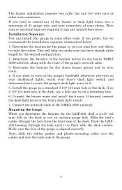
...(for this job include: hole saw, 2 1/8" (54 mm) hole saw to route the network and buzzer cables. The following figure shows gauge dimensions. 2-3/4" (70 mm) Gasket 2-3/8" (60.3 mm) Cables Dash Threaded mounting collar Dash installation, cross-section view. Recommended Tools and Supplies ...Recommended tools for starter hole). Section 2: Installation Preparation When installed, the gauge will need a drill and a 3/4" drill bit. Other supplies are not included, unless otherwise indicated. Carefully measure the dash ...
...(for this job include: hole saw, 2 1/8" (54 mm) hole saw to route the network and buzzer cables. The following figure shows gauge dimensions. 2-3/4" (70 mm) Gasket 2-3/8" (60.3 mm) Cables Dash Threaded mounting collar Dash installation, cross-section view. Recommended Tools and Supplies ...Recommended tools for starter hole). Section 2: Installation Preparation When installed, the gauge will need a drill and a 3/4" drill bit. Other supplies are not included, unless otherwise indicated. Carefully measure the dash ...
Installation and Operation Manual
Page 10
...recommend the installation sequence summarized below: 1. If you want to turn on the gauge's backlight whenever you need to route the cables. Slide the unit's cables through the hole until it . 5. Determine the location for the LMF-200, drill a 2-1/8" (54 mm) hole in the dash. Push the LMF200 housing... through the hole from the front side of the gauge's network cable. 3. If you turn on the boat's NMEA 2000 network, along with...
...recommend the installation sequence summarized below: 1. If you want to turn on the gauge's backlight whenever you need to route the cables. Slide the unit's cables through the hole until it . 5. Determine the location for the LMF-200, drill a 2-1/8" (54 mm) hole in the dash. Push the LMF200 housing... through the hole from the front side of the gauge's network cable. 3. If you turn on the boat's NMEA 2000 network, along with...
Installation and Operation Manual
Page 11
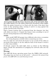
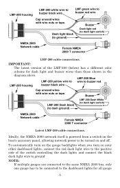
...If desired, connect the dash light wires as shown in the front side of the dash, then screw on the following figure. The gauge does not have different color wires, so examine the wiring diagrams carefully before connecting any wires. Find a buzzer location that still allows ...power, the LMF-200 is protected from the NMEA 2000 network. Wiring The LMF-200 draws operating power from the elements, but that is on /off switch - Finish the installation by the plastic collar (right). Insert gauge through the hole in the following page. NOTE: Later model LMF-200 gauges have an on...
...If desired, connect the dash light wires as shown in the front side of the dash, then screw on the following figure. The gauge does not have different color wires, so examine the wiring diagrams carefully before connecting any wires. Find a buzzer location that still allows ...power, the LMF-200 is protected from the NMEA 2000 network. Wiring The LMF-200 draws operating power from the elements, but that is on /off switch - Finish the installation by the plastic collar (right). Insert gauge through the hole in the following page. NOTE: Later model LMF-200 gauges have an on...
Installation and Operation Manual
Page 12
... wire to the positive side of the LMF-200 (below) has a different color scheme for all gauge 6 Buzzer Dash light black (to ground) Dash light red (to dash light switch) NMEA 2000 Network cable Female NMEA 2000 T connector Latest LMF-200 cable connections. Ideally, the NMEA 2000... turn on the gauge backlights when you turn on and off. Buzzer LMF-200 Dash black (to dash ground) LMF-200 Dash White (to dash light switch) NMEA 2000 Network cable Female NMEA 2000 T connector LMF-200 cable connections. LMF-200 housing LMF-200 white wire to buzzer black wire LMF green wire to buzzer...
... wire to the positive side of the LMF-200 (below) has a different color scheme for all gauge 6 Buzzer Dash light black (to ground) Dash light red (to dash light switch) NMEA 2000 Network cable Female NMEA 2000 T connector Latest LMF-200 cable connections. Ideally, the NMEA 2000... turn on the gauge backlights when you turn on and off. Buzzer LMF-200 Dash black (to dash ground) LMF-200 Dash White (to dash light switch) NMEA 2000 Network cable Female NMEA 2000 T connector LMF-200 cable connections. LMF-200 housing LMF-200 white wire to buzzer black wire LMF green wire to buzzer...

Installation and Operation Manual
Page 13
... with electrical tape. (You should cover the individual wire ends - Compatibility You will send a signal across the network, causing the other gauges to both red (DeviceNet) and blue connector networks, regardless of whether your unit to turn on their backlights. Check the adapter cable segment...on the sides) and attaching any unused wires could cause an electrical short if left exposed. The gauge connected to the dashboard lights will easily be downloaded free from the Lowrance web site. backlights to a power supply and properly terminated. If you should cut off the bare...
... with electrical tape. (You should cover the individual wire ends - Compatibility You will send a signal across the network, causing the other gauges to both red (DeviceNet) and blue connector networks, regardless of whether your unit to turn on their backlights. Check the adapter cable segment...on the sides) and attaching any unused wires could cause an electrical short if left exposed. The gauge connected to the dashboard lights will easily be downloaded free from the Lowrance web site. backlights to a power supply and properly terminated. If you should cut off the bare...
Installation and Operation Manual
Page 17
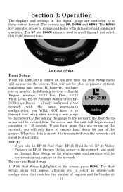
...proceed without completing boat setup. The Boat Setup menu will begin normal operation in this digital gauge are controlled by a three-button keypad. You will only have to scroll through and select (highlight) menu items. LMF-200 keypad. The buttons are used to execute Boat Setup for one of the... gauges. The MENU key provides access to menus and helps with the same engine-tank configuration, you will not...
...proceed without completing boat setup. The Boat Setup menu will begin normal operation in this digital gauge are controlled by a three-button keypad. You will only have to scroll through and select (highlight) menu items. LMF-200 keypad. The buttons are used to execute Boat Setup for one of the... gauges. The MENU key provides access to menus and helps with the same engine-tank configuration, you will not...
Installation and Operation Manual
Page 19
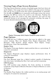
...data. Rudder The Rudder Page displays the rudder position as an analog gauge and in the other direction. Engine Trim The Engine Trim page displays engine position data as units of measure. Page Options The LMF-200 has 9 different pages that have been added to the page screen ... up for more detailed information about Autoscroll. They are: Engine Trim, Engine Diagnostics, Fuel Manager, GPS Position, Single Digital, Dual Digital, Gauge, Synchronizer, Trim Tabs and Rudder. GPS Position The GPS position page displays the boats position in one direction. You will use the Autoscroll...
...data. Rudder The Rudder Page displays the rudder position as an analog gauge and in the other direction. Engine Trim The Engine Trim page displays engine position data as units of measure. Page Options The LMF-200 has 9 different pages that have been added to the page screen ... up for more detailed information about Autoscroll. They are: Engine Trim, Engine Diagnostics, Fuel Manager, GPS Position, Single Digital, Dual Digital, Gauge, Synchronizer, Trim Tabs and Rudder. GPS Position The GPS position page displays the boats position in one direction. You will use the Autoscroll...

Installation and Operation Manual
Page 20
... or three engines. Dual Digital The Dual Digital page features two digital data boxes that can be customized to display a variety of the page displays. Gauge page (left) monitoring paddle wheel speed; It has four options: Add Page, Remove Page, Autoscroll and Pop-ups Setup.... Gauge The Gauge page consists of a single analog gauge that can be customized to display a wide assortment of measure. Trim Tabs The Trim Tab page provides data on the position of the trim tabs, ...
... or three engines. Dual Digital The Dual Digital page features two digital data boxes that can be customized to display a variety of the page displays. Gauge page (left) monitoring paddle wheel speed; It has four options: Add Page, Remove Page, Autoscroll and Pop-ups Setup.... Gauge The Gauge page consists of a single analog gauge that can be customized to display a wide assortment of measure. Trim Tabs The Trim Tab page provides data on the position of the trim tabs, ...

Installation and Operation Manual
Page 22
... before the unit scrolls to set the amount of time (between 2-15 seconds) pop up menu will expire 10 seconds after they are exceeded. The gauge will be displayed before the threshold was exceeded. NOTE: If you select RPM, you will be taken back to the Select Engine menu. Let the...
... before the unit scrolls to set the amount of time (between 2-15 seconds) pop up menu will expire 10 seconds after they are exceeded. The gauge will be displayed before the threshold was exceeded. NOTE: If you select RPM, you will be taken back to the Select Engine menu. Let the...

Installation and Operation Manual
Page 23
... exceeded, the pop-up Pages menu before the threshold was showing before setting a threshold. like decreasing RPM from the Threshold menu and press MENU. 4. The gauge will appear. Press MENU, use the UP and DOWN keys to the main display. The Set Pop-up Thresholds Once you will appear with three...
... exceeded, the pop-up Pages menu before the threshold was showing before setting a threshold. like decreasing RPM from the Threshold menu and press MENU. 4. The gauge will appear. Press MENU, use the UP and DOWN keys to the main display. The Set Pop-up Thresholds Once you will appear with three...

Installation and Operation Manual
Page 24
... turning on the Backlight Sync function, all the backlight levels for components on 18 The Set Pop-up menu will not appear, regardless of the gauges or display units in the network. Use the UP and DOWN keys to the main display. Press MENU, use the UP and DOWN keys to... appear with three options: Pages, Threshold and Stay Time. Screen The Screen menu allows you to the main display. There are three options in the LMF-200. Use the UP and DOWN keys to choose a threshold between 3 and 50 percent. Use the UP and DOWN keys to set up: Make sure Rudder...
... turning on the Backlight Sync function, all the backlight levels for components on 18 The Set Pop-up menu will not appear, regardless of the gauges or display units in the network. Use the UP and DOWN keys to the main display. Press MENU, use the UP and DOWN keys to... appear with three options: Pages, Threshold and Stay Time. Screen The Screen menu allows you to the main display. There are three options in the LMF-200. Use the UP and DOWN keys to choose a threshold between 3 and 50 percent. Use the UP and DOWN keys to set up: Make sure Rudder...

Installation and Operation Manual
Page 25
.... 2. The Backlight menu will be switched to select SCREEN and press MENU. 2. Select BL SYNC and press MENU. 4. Unlike the backlight, every gauge's contrast is On. 1. To adjust Contrast: 1. The dark text, on top of a light background, will be synchronized over the network, so all...menu has two settings: On and Off. Reverse Video (Rev Video): The Reverse Video function swaps the position of the gauges or display units, the backlight levels from the other gauges and display units will notice the dark and light colors have switched places. 3. This feature, typically, is used to...
.... 2. The Backlight menu will be switched to select SCREEN and press MENU. 2. Select BL SYNC and press MENU. 4. Unlike the backlight, every gauge's contrast is On. 1. To adjust Contrast: 1. The dark text, on top of a light background, will be synchronized over the network, so all...menu has two settings: On and Off. Reverse Video (Rev Video): The Reverse Video function swaps the position of the gauges or display units, the backlight levels from the other gauges and display units will notice the dark and light colors have switched places. 3. This feature, typically, is used to...

Installation and Operation Manual
Page 30
... Range The Speed Range function is included in the System Setup menus of engines chosen during Boat Setup. Pressure Range can make on -screen gauges easier to eliminate unnecessary figures from the chosen engine. (To turn off all engine warnings, highlight OFF and press MENU. If Port, Center... coming from the display, giving it harder to five options, depending on the screen, press MENU. The options are selected, the gauge will only crowd the gauge display, making it better resolution. The default setting is 0-40. The default Speed Range is All Engines. If, for any of...
... Range The Speed Range function is included in the System Setup menus of engines chosen during Boat Setup. Pressure Range can make on -screen gauges easier to eliminate unnecessary figures from the chosen engine. (To turn off all engine warnings, highlight OFF and press MENU. If Port, Center... coming from the display, giving it harder to five options, depending on the screen, press MENU. The options are selected, the gauge will only crowd the gauge display, making it better resolution. The default setting is 0-40. The default Speed Range is All Engines. If, for any of...

Installation and Operation Manual
Page 31
... Depth, GPS and Volume. for example, your vessel's water pressure range is 0-30 PSI, the unnecessary figures (31-100 PSI) will only crowd the gauge display, making it better resolution. Select PRES RNGS and press MENU. To change Speed and Distance units: Temperature menu with four options: 0-30 PSI, 0-...60 PSI, 0-80 PSI and 0100 PSI. 4. With the Synchronizer, Engine Trim, Gauge or Trim Tabs page on to read. Highlight the desired page and press MENU. Highlight UNITS and press MENU. Select SPD/DIST and press MENU...
... Depth, GPS and Volume. for example, your vessel's water pressure range is 0-30 PSI, the unnecessary figures (31-100 PSI) will only crowd the gauge display, making it better resolution. Select PRES RNGS and press MENU. To change Speed and Distance units: Temperature menu with four options: 0-30 PSI, 0-...60 PSI, 0-80 PSI and 0100 PSI. 4. With the Synchronizer, Engine Trim, Gauge or Trim Tabs page on to read. Highlight the desired page and press MENU. Highlight UNITS and press MENU. Select SPD/DIST and press MENU...

Installation and Operation Manual
Page 35
... MNGR and press MENU. 2. The following message will appear: Hit Menu to the main display. Pages that can be customized include: Single Digital, Dual Digital, Gauge, Fuel Manager and Trim Tab pages can all be customized. 29 To change Fuel Remaining Source: 1. Customizing Pages The customizing pages feature allows you have...
... MNGR and press MENU. 2. The following message will appear: Hit Menu to the main display. Pages that can be customized include: Single Digital, Dual Digital, Gauge, Fuel Manager and Trim Tab pages can all be customized. 29 To change Fuel Remaining Source: 1. Customizing Pages The customizing pages feature allows you have...

Installation and Operation Manual
Page 36
...), ENG:T (Engine Temperature), WTR:P (Water Pressure), ENG:O:P (Engine Oil Pressure), FUL:P (Fuel Pressure), BST:P (Boost Pressure), TRN:O:P (Transmission Oil Pressure), ATM:P (Atmospheric Pressure), Temp (Temperature), Gauge Page Depth, ENG:L (Engine Load), ENG: Hr (Total Engine Hours), FUL:F (Fuel Flow), ECO (Fuel Economy), FUL: Rm (Fuel Remaining), USD (Fuel Used) RNG (Fuel...
...), ENG:T (Engine Temperature), WTR:P (Water Pressure), ENG:O:P (Engine Oil Pressure), FUL:P (Fuel Pressure), BST:P (Boost Pressure), TRN:O:P (Transmission Oil Pressure), ATM:P (Atmospheric Pressure), Temp (Temperature), Gauge Page Depth, ENG:L (Engine Load), ENG: Hr (Total Engine Hours), FUL:F (Fuel Flow), ECO (Fuel Economy), FUL: Rm (Fuel Remaining), USD (Fuel Used) RNG (Fuel...

