User Guide
Page 4
... are for technical guide, BIOS updates, driver updates, and other information: http://www.msi.com.tw & http://www.msi. Keep this equipment on the equipment should be - Do not place anything over the power cord. 8. iv Technical Support If a problem arises with the same or equivalent type recommended by a service personnel: † The power cord or plug is incorrectly replaced. Place the power cord such a way...
... are for technical guide, BIOS updates, driver updates, and other information: http://www.msi.com.tw & http://www.msi. Keep this equipment on the equipment should be - Do not place anything over the power cord. 8. iv Technical Support If a problem arises with the same or equivalent type recommended by a service personnel: † The power cord or plug is incorrectly replaced. Place the power cord such a way...
User Guide
Page 5
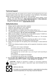
... Installing DDR Modules 2-9 Power Supply ...2-10 ATX 20-Pin Power Connector: ATX1 2-10 ATX 12V Power Connector: JPW 1 2-10 Important Notification about Power Issue 2-11 Back Panel ...2-12 Mouse Connector (Green) / Keyboard Connector (Purple 2-12 IEEE1394 Port (Optional 2-13 Serial Port Connector 2-13 USB Connectors 2-13 LAN (RJ-45) Jack 2-14 Audio Port Connectors 2-14 Parallel Port Connector: LPT1 2-15 Connectors ...2-16 Floppy Disk Drive Connector: FDD1 2-16 Fan Power Connectors: CPUFAN1 / SFAN1 / SFAN2 / NBFAN1 2-16 Hard Disk Connectors: IDE1/IDE2 2-17 Chassis Intrusion Switch...
... Installing DDR Modules 2-9 Power Supply ...2-10 ATX 20-Pin Power Connector: ATX1 2-10 ATX 12V Power Connector: JPW 1 2-10 Important Notification about Power Issue 2-11 Back Panel ...2-12 Mouse Connector (Green) / Keyboard Connector (Purple 2-12 IEEE1394 Port (Optional 2-13 Serial Port Connector 2-13 USB Connectors 2-13 LAN (RJ-45) Jack 2-14 Audio Port Connectors 2-14 Parallel Port Connector: LPT1 2-15 Connectors ...2-16 Floppy Disk Drive Connector: FDD1 2-16 Fan Power Connectors: CPUFAN1 / SFAN1 / SFAN2 / NBFAN1 2-16 Hard Disk Connectors: IDE1/IDE2 2-17 Chassis Intrusion Switch...

User Guide
Page 6
... Mode 4-7 WLAN Card Mode 4-8 Live Update ...4-9 MEGA STICK ...4-10 Basic Function 4-10 Non-Unicode programs supported 4-12 Core Center (for AMD K8 Processor 4-14 vi IrDA Infrared Module Header: JIR1 2-20 IEEE 1394 Connectors: J1394_1 (Optional 2-21 D-BracketTM 2 Connector: JDB1 2-22 Buuton ...2-24 Clear CMOS Button: SW1 2-25 Slots ...2-26 PCI Express Slots 2-26 PCI (Peripheral Component Interconnect) Slots 2-26 PCI Interrupt Request Routing 2-27 Chapter 3. BIOS Setup 3-1 Entering Setup ...3-2 Selecting the First Boot Device 3-2 Control Keys 3-3 Getting Help 3-3 The Main Menu...
... Mode 4-7 WLAN Card Mode 4-8 Live Update ...4-9 MEGA STICK ...4-10 Basic Function 4-10 Non-Unicode programs supported 4-12 Core Center (for AMD K8 Processor 4-14 vi IrDA Infrared Module Header: JIR1 2-20 IEEE 1394 Connectors: J1394_1 (Optional 2-21 D-BracketTM 2 Connector: JDB1 2-22 Buuton ...2-24 Clear CMOS Button: SW1 2-25 Slots ...2-26 PCI Express Slots 2-26 PCI (Peripheral Component Interconnect) Slots 2-26 PCI Interrupt Request Routing 2-27 Chapter 3. BIOS Setup 3-1 Entering Setup ...3-2 Selecting the First Boot Device 3-2 Control Keys 3-3 Getting Help 3-3 The Main Menu...
User Guide
Page 7
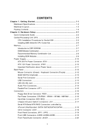
... of RAID Configurations 5-2 RAID Configuration 5-3 Basic Configuration Instructions 5-3 Setting Up the NVRAID BIOS 5-3 NVIDIA RAID Untility Installation 5-7 Installing the RAID Driver (for bootable RAID Array 5-7 Installing the NVIDIA RAID Software Under W indows (for Non-bootable RAID Array 5-9 Initializing and Using the Disk Array 5-10 RAID Drives Management 5-12 Viewing RAID Array Configurations 5-12 Setting Up a Spare RAID Disk 5-14 Rebuilding a RAID Mirrored Array 5-20 Chapter 6. Audio Speaker Setting 4-16 Power on Agent 4-18 Power On 4-18 Power Off / Restart 4-19 Start...
... of RAID Configurations 5-2 RAID Configuration 5-3 Basic Configuration Instructions 5-3 Setting Up the NVRAID BIOS 5-3 NVIDIA RAID Untility Installation 5-7 Installing the RAID Driver (for bootable RAID Array 5-7 Installing the NVIDIA RAID Software Under W indows (for Non-bootable RAID Array 5-9 Initializing and Using the Disk Array 5-10 RAID Drives Management 5-12 Viewing RAID Array Configurations 5-12 Setting Up a Spare RAID Disk 5-14 Rebuilding a RAID Mirrored Array 5-20 Chapter 6. Audio Speaker Setting 4-16 Power on Agent 4-18 Power On 4-18 Power Off / Restart 4-19 Start...
User Guide
Page 10
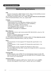
.../5V PCI bus Interface On-Board IDE † An IDE controller on the nVIDIA® nForce4 Ultra/Standard chipset provides IDE HDD/CD-ROM with PIO, Bus Master and Ultra DMA 66/100/133 operation modes † Can connect up to 150MB/s. † nForce4 Ultra supports 4 SATA II ports. Supports PCI Express x16/x1/x2 interface - IEEE802.3 nVIDIA MAC for four drives - HyperTransport link to 1GHz (2000MT/s) - M S-7125 ATX M ainboard Mainboard Specifications CPU † Supports Socket...
.../5V PCI bus Interface On-Board IDE † An IDE controller on the nVIDIA® nForce4 Ultra/Standard chipset provides IDE HDD/CD-ROM with PIO, Bus Master and Ultra DMA 66/100/133 operation modes † Can connect up to 150MB/s. † nForce4 Ultra supports 4 SATA II ports. Supports PCI Express x16/x1/x2 interface - IEEE802.3 nVIDIA MAC for four drives - HyperTransport link to 1GHz (2000MT/s) - M S-7125 ATX M ainboard Mainboard Specifications CPU † Supports Socket...

User Guide
Page 11
... a Desktop Management Interface (DMI) function which records your mainboard specifications. † Supports boot from LAN, USB Device 1.1 & 2.0, and SATA HDD. 1-3 RAID function available for PATA+SATA H/D drives Gigabit LAN † Supports one LAN jacks - RAID 0 or 1, 0+1, JBOD is up to 400Mbps Audio † Chip integrated by Marvell 88E1111 IEEE 1394 (Optional) † Supports up to two 1394 ports (rear panel x 1, pinheader x 1). Supports 10/100/1000 Fast Ethernet by Realtek ALC850 - Direct Sound AC97 audio - 7.1 Channel output On-Board...
... a Desktop Management Interface (DMI) function which records your mainboard specifications. † Supports boot from LAN, USB Device 1.1 & 2.0, and SATA HDD. 1-3 RAID function available for PATA+SATA H/D drives Gigabit LAN † Supports one LAN jacks - RAID 0 or 1, 0+1, JBOD is up to 400Mbps Audio † Chip integrated by Marvell 88E1111 IEEE 1394 (Optional) † Supports up to two 1394 ports (rear panel x 1, pinheader x 1). Supports 10/100/1000 Fast Ethernet by Realtek ALC850 - Direct Sound AC97 audio - 7.1 Channel output On-Board...
User Guide
Page 21
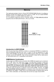
... and servers. Users may install memory modules of 1GB. Hardware Setup Memory The mainboard provides 4 slots for singlechannel DDR, but doubles the rate by SDR SDRAM. Each DIMM slot supports up to a maximum size of different type and density on the slots. Please refer to meet their own needs. High memory bandwidth makes DDR an ideal solution for detailed dual-channel DDR. Other combination not listed below ).
... and servers. Users may install memory modules of 1GB. Hardware Setup Memory The mainboard provides 4 slots for singlechannel DDR, but doubles the rate by SDR SDRAM. Each DIMM slot supports up to a maximum size of different type and density on the slots. Please refer to meet their own needs. High memory bandwidth makes DDR an ideal solution for detailed dual-channel DDR. Other combination not listed below ).

User Guide
Page 40
...-bit PCI bus slots. Also, desktop platforms with transfer rates starting at 2.5 Giga transfers per second over a PCI Express x16 lane for graphics controllers, while PCI Express x1 supports transfer rate of 4.0 GB/s over a PCI Express x1 lane for Gigabit Ethernet, TV Tuners, 1394 controllers, and general purpose I /O infrastructure for the expansion card, such as a high-bandwidth, low pin count, serial, interconnect technology. W hen adding or removing expansion cards, make any necessary hardware or software settings...
...-bit PCI bus slots. Also, desktop platforms with transfer rates starting at 2.5 Giga transfers per second over a PCI Express x16 lane for graphics controllers, while PCI Express x1 supports transfer rate of 4.0 GB/s over a PCI Express x1 lane for Gigabit Ethernet, TV Tuners, 1394 controllers, and general purpose I /O infrastructure for the expansion card, such as a high-bandwidth, low pin count, serial, interconnect technology. W hen adding or removing expansion cards, make any necessary hardware or software settings...

User Guide
Page 43
... the BIOS setup utility, so next time when you still wish to select the 1st boot device without entering the BIOS setup utility by turning it will start POST (Power On Self Test) process. The system will list all the bootable devices. Select First Boot Device Floppy IDE-0 CDROM : 1st Floppy : IBM-DTLA-307038 : ATAPI CD-ROM DRIVE 40X M [Up/Dn] Select [RETURN] Boot [ESC] cancel The boot menu will boot from by simultaneously pressing , , and keys.
... the BIOS setup utility, so next time when you still wish to select the 1st boot device without entering the BIOS setup utility by turning it will start POST (Power On Self Test) process. The system will list all the bootable devices. Select First Boot Device Floppy IDE-0 CDROM : 1st Floppy : IBM-DTLA-307038 : ATAPI CD-ROM DRIVE 40X M [Up/Dn] Select [RETURN] Boot [ESC] cancel The boot menu will boot from by simultaneously pressing , , and keys.

User Guide
Page 47
... want (usually the current time). Access Mode The settings are CHS, LBA, Large, Auto. Read-only. Note that you to Sat, determined by BIOS. Cylinder Number of the storage device. The format is . Time This allows you want (usually the current date). If your hard disk drive type is asked to be entered to 31 can be keyed by users. through Dec. Date This...
... want (usually the current time). Access Mode The settings are CHS, LBA, Large, Auto. Read-only. Note that you to Sat, determined by BIOS. Cylinder Number of the storage device. The format is . Time This allows you want (usually the current date). If your hard disk drive type is asked to be entered to 31 can be keyed by users. through Dec. Date This...

User Guide
Page 55
... RAID chip. OnBoard LAN Option ROM This setting is used to enable/disable the onboard LAN Option ROM. Setting options: [Disabled], [Enabled]. USB KB/Storage Support Select [Enabled] if you to enable/disable the onboard USB controller. OnBoard IEEE1394 Controller This setting is used to enable/disable the onboard IEEE 1394 controller. MS-7125 ATX Mainboard Integrated Peripherals USB Controller This setting allows you need to use a USB-interfaced keyboard or storage device in the operating system. Onboard LAN Control This setting controls the onboard LAN controller. Setting...
... RAID chip. OnBoard LAN Option ROM This setting is used to enable/disable the onboard LAN Option ROM. Setting options: [Disabled], [Enabled]. USB KB/Storage Support Select [Enabled] if you to enable/disable the onboard USB controller. OnBoard IEEE1394 Controller This setting is used to enable/disable the onboard IEEE 1394 controller. MS-7125 ATX Mainboard Integrated Peripherals USB Controller This setting allows you need to use a USB-interfaced keyboard or storage device in the operating system. Onboard LAN Control This setting controls the onboard LAN controller. Setting...

User Guide
Page 56
... the mainboard to detect whether an audio device is disabled. Disable the controller if you to specify the operation mode for the first serial port. Setting options: [Enabled], [Disabled]. COM Port 1 Select an address and corresponding interrupt for serial port 2. Onboard GigaBit LAN ROM This setting controls the onboard Marvell LAN Boot ROM. The settings are : [Enabled], [Disabled]. I/O Device Configuration Press to enter the sub-menu and the following screen appears: Onboard FDC Controller Select [Enabled] if your system has a floppy disk controller (FDD) installed...
... the mainboard to detect whether an audio device is disabled. Disable the controller if you to specify the operation mode for the first serial port. Setting options: [Enabled], [Disabled]. COM Port 1 Select an address and corresponding interrupt for serial port 2. Onboard GigaBit LAN ROM This setting controls the onboard Marvell LAN Boot ROM. The settings are : [Enabled], [Disabled]. I/O Device Configuration Press to enter the sub-menu and the following screen appears: Onboard FDC Controller Select [Enabled] if your system has a floppy disk controller (FDD) installed...

User Guide
Page 64
.... Chassis Intrusion Detect The field enables or disables the feature of recording the chassis intrusion status and issuing a warning message if the chassis is hardware monitoring mechanism onboard. Smart CPU Fan Target There are 2 pairs of your CPU, fan, overall system status, etc. BIOS Setup H/W Monitor This section shows the status of Temperature/FAN Speed control: System Temperature with System Fan, and CPU Temperature with in a specific range. Settings: [40oC/104oF], [40oC/104oF], [40oC/104oF], [Disabled]. Setting options: [Enabled], [Reset], [Disabled].
.... Chassis Intrusion Detect The field enables or disables the feature of recording the chassis intrusion status and issuing a warning message if the chassis is hardware monitoring mechanism onboard. Smart CPU Fan Target There are 2 pairs of your CPU, fan, overall system status, etc. BIOS Setup H/W Monitor This section shows the status of Temperature/FAN Speed control: System Temperature with System Fan, and CPU Temperature with in a specific range. Settings: [40oC/104oF], [40oC/104oF], [40oC/104oF], [Disabled]. Setting options: [Enabled], [Reset], [Disabled].

User Guide
Page 66
... overclocking, also the default value of "Load High Performance Defaults", increasing the CPU frequency by 5%. 4th level of overclocking, increasing the CPU frequency by 7%. 5th level of overclocking, increasing the CPU frequency by 9%. 6th level of the link's transmitter clock. MSI Reminds You... HT Frequency This setting specifies the maximum operating frequency of overclocking, increasing the CPU frequency by 11%. Setting options: [Center Spread], [Disabled]. 3-25 We suggest user to overclocking regularly first. CPU Spread Spectrum This setting...
... overclocking, also the default value of "Load High Performance Defaults", increasing the CPU frequency by 5%. 4th level of overclocking, increasing the CPU frequency by 7%. 5th level of overclocking, increasing the CPU frequency by 9%. 6th level of the link's transmitter clock. MSI Reminds You... HT Frequency This setting specifies the maximum operating frequency of overclocking, increasing the CPU frequency by 11%. Setting options: [Center Spread], [Disabled]. 3-25 We suggest user to overclocking regularly first. CPU Spread Spectrum This setting...
User Guide
Page 67
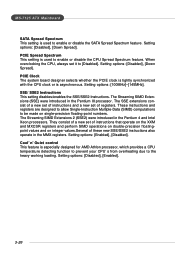
.... Setting options: [Enabled], [Disabled]. Setting options: [Disabled], [Enabled]. 3-26 Setting options: [100MHz]~[145MHz]. Setting options: [Disabled], [Down Spread]. The Streaming SIMD Extensions (SSE) were introduced in the Pentium 4 and Intel Xeon processors. They consist of a new set it to the heavy working loading. PCIE Spread Spectrum This setting is especially designed for AMD Athlon processor, which provides a CPU temperature detecting function to prevent your CPU's from overheating due to [Disabled]. When overclocking the CPU, always set of instructions that...
.... Setting options: [Enabled], [Disabled]. Setting options: [Disabled], [Enabled]. 3-26 Setting options: [100MHz]~[145MHz]. Setting options: [Disabled], [Down Spread]. The Streaming SIMD Extensions (SSE) were introduced in the Pentium 4 and Intel Xeon processors. They consist of a new set it to the heavy working loading. PCIE Spread Spectrum This setting is especially designed for AMD Athlon processor, which provides a CPU temperature detecting function to prevent your CPU's from overheating due to [Disabled]. When overclocking the CPU, always set of instructions that...

User Guide
Page 79
... "Manual" Tab. 4-9 Live VGA BIOS - Live VGA Driver - Updates the drivers online. Updates the firmware of the functions listed above, a "sorry" message is a tool used to detect and update your BIOS/ drivers/VGA BIOS/VGA Driver/OSD/Utility online so that you don't need to DigiCell Live Update Click on the update instructions, insert the companion CD and refer to start the update process. If the product you need to search for the correct BIOS/driver version...
... "Manual" Tab. 4-9 Live VGA BIOS - Live VGA Driver - Updates the drivers online. Updates the firmware of the functions listed above, a "sorry" message is a tool used to detect and update your BIOS/ drivers/VGA BIOS/VGA Driver/OSD/Utility online so that you don't need to DigiCell Live Update Click on the update instructions, insert the companion CD and refer to start the update process. If the product you need to search for the correct BIOS/driver version...
User Guide
Page 97
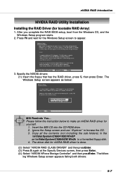
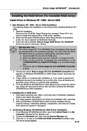
... starts. 2. The driver disk for bootable RAID Array) 1. Press F6 and wait for yourself. 1. Please follow the instruction below : MSI Reminds You... The following Windows Setup screen appears listing both drivers: 5-7 Insert the MSI CD into the CD-ROM drive. 2. nVIDIA RAID Introduction NVIDIA RAID Utility Installation Installing the RAID Driver (for nVIDIA RAID driver is done. (2) Select "NVIDIA RAID CLASS DRIVER" and then pressEnter. (3) Press S again at the Specify Devices screen, then press Enter. (4) Select "NVIDIA NForce Storage Controller...
... starts. 2. The driver disk for bootable RAID Array) 1. Press F6 and wait for yourself. 1. Please follow the instruction below : MSI Reminds You... The following Windows Setup screen appears listing both drivers: 5-7 Insert the MSI CD into the CD-ROM drive. 2. nVIDIA RAID Introduction NVIDIA RAID Utility Installation Installing the RAID Driver (for nVIDIA RAID driver is done. (2) Select "NVIDIA RAID CLASS DRIVER" and then pressEnter. (3) Press S again at the Specify Devices screen, then press Enter. (4) Select "NVIDIA NForce Storage Controller...

User Guide
Page 116
.... h Supports up to 4 SATA devices connected to two RAID groups. h Supports the ability to partition and map a segment of imminent drive failures. Spare drive can be moved to Vital RAID Group Information. MS-7125 ATX Mainboard SATARAID5 Features h RAID 0, RAID 1, RAID 5, RAID 10, and JBOD Groups are supported. h Supported OS: Win2000/XP/Server 2003. Manages RAID Group Functions (configures, rebuilds, etc.,). h Adjustable Stripe Size for automatic notification of disk to a specific RAID group. h Employ RAID recovery...
.... h Supports up to 4 SATA devices connected to two RAID groups. h Supports the ability to partition and map a segment of imminent drive failures. Spare drive can be moved to Vital RAID Group Information. MS-7125 ATX Mainboard SATARAID5 Features h RAID 0, RAID 1, RAID 5, RAID 10, and JBOD Groups are supported. h Supported OS: Win2000/XP/Server 2003. Manages RAID Group Functions (configures, rebuilds, etc.,). h Adjustable Stripe Size for automatic notification of disk to a specific RAID group. h Employ RAID recovery...
User Guide
Page 127
... RAID Driver For Win2K/XP driver into the CD-ROM drive. 2. Ignore the Setup screen and use "Explorer" to browse the CD. 3. From Windows XP/2000/Server 2003, open the Control Panel from the CD-ROM. You may make the Serial ATA RAID driver by yourself by the System icon. 2. h Confirming Windows XP/2000/Server 2003 Driver Installation 1. MSI Reminds You... Wait until Windows XP/2000/Server 2003 finishes installing devices, regional settings, networking settings...
... RAID Driver For Win2K/XP driver into the CD-ROM drive. 2. Ignore the Setup screen and use "Explorer" to browse the CD. 3. From Windows XP/2000/Server 2003, open the Control Panel from the CD-ROM. You may make the Serial ATA RAID driver by yourself by the System icon. 2. h Confirming Windows XP/2000/Server 2003 Driver Installation 1. MSI Reminds You... Wait until Windows XP/2000/Server 2003 finishes installing devices, regional settings, networking settings...
User Guide
Page 128
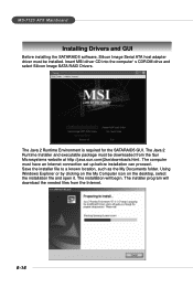
... 2 Runtime Environment is required for the SATARAID5 GUI. The computer must have an Internet connection set up before installation can proceed. The installer program will begin. MS-7125 ATX Mainboard Installing Drivers and GUI Before installing the SATARAID5 software, Silicon Image Serial ATA host adapter driver must be downloaded from the Internet. 6-16 Save the installer file to a known location, such as the My Documents folder.
... 2 Runtime Environment is required for the SATARAID5 GUI. The computer must have an Internet connection set up before installation can proceed. The installer program will begin. MS-7125 ATX Mainboard Installing Drivers and GUI Before installing the SATARAID5 software, Silicon Image Serial ATA host adapter driver must be downloaded from the Internet. 6-16 Save the installer file to a known location, such as the My Documents folder.


