
User Guide
Page 6
... WLAN Card Mode 4-8 Live Update ...4-9 MEGA STICK ...4-10 Basic Function 4-10 Non-Unicode programs supported 4-12 Core Center (for AMD K8 Processor 4-14 vi IrDA Infrared Module Header: JIR1 2-20 IEEE 1394 Connectors: J1394_1 (Optional 2-21 D-BracketTM 2 Connector: ...Interconnect) Slots 2-26 PCI Interrupt Request Routing 2-27 Chapter 3. BIOS Setup 3-1 Entering Setup ...3-2 Selecting the First Boot Device 3-2 Control Keys 3-3 Getting Help 3-3 The Main Menu ...3-4 Standard CMOS Features 3-6 Advanced BIOS Features 3-8 Advanced Chipset Features 3-11 Integrated Peripherals 3-12 Power...
... WLAN Card Mode 4-8 Live Update ...4-9 MEGA STICK ...4-10 Basic Function 4-10 Non-Unicode programs supported 4-12 Core Center (for AMD K8 Processor 4-14 vi IrDA Infrared Module Header: JIR1 2-20 IEEE 1394 Connectors: J1394_1 (Optional 2-21 D-BracketTM 2 Connector: ...Interconnect) Slots 2-26 PCI Interrupt Request Routing 2-27 Chapter 3. BIOS Setup 3-1 Entering Setup ...3-2 Selecting the First Boot Device 3-2 Control Keys 3-3 Getting Help 3-3 The Main Menu ...3-4 Standard CMOS Features 3-6 Advanced BIOS Features 3-8 Advanced Chipset Features 3-11 Integrated Peripherals 3-12 Power...

User Guide
Page 34
...Connectivity Design Guide. You must configure the setting through the BIOS setup to use to control headphone amplifier No pin Left channel audio signal to front panel Left channel audio signal return from front panel MSI Reminds You... M S-7125 ATX M ainboard Front Panel... PIN SIGNAL DESCRIPTION 1 JAUD1 2 3 2 10 4 1 9 5 6 7 8 9 10 AUD_MIC AUD_GND AUD_MIC_BIAS AUD_VCC AUD_FPOUT_R AUD_RET_R HP_ON KEY AUD_FPOUT_L AUD_RET_L Front panel microphone input signal Ground used by analog audio circuits Microphone power Filtered +5V used by analog audio circuits Right channel audio...
...Connectivity Design Guide. You must configure the setting through the BIOS setup to use to control headphone amplifier No pin Left channel audio signal to front panel Left channel audio signal return from front panel MSI Reminds You... M S-7125 ATX M ainboard Front Panel... PIN SIGNAL DESCRIPTION 1 JAUD1 2 3 2 10 4 1 9 5 6 7 8 9 10 AUD_MIC AUD_GND AUD_MIC_BIAS AUD_VCC AUD_FPOUT_R AUD_RET_R HP_ON KEY AUD_FPOUT_L AUD_RET_L Front panel microphone input signal Ground used by analog audio circuits Microphone power Filtered +5V used by analog audio circuits Right channel audio...

User Guide
Page 43
... the boot menu similar to select the 1st boot device without entering the BIOS setup utility by simultaneously pressing , , and keys. When the same message as listed above appears on the screen, press key to respond in the BIOS setup utility, so next time when you to enter Setup. The selection ... DEL to enter SETUP If the message disappears before you respond and you want to enter Setup, restart the system by using arrow keys, then press . MSI Reminds You... Select the one you still wish to boot from the selected device. The system will boot from by turning it will...
... the boot menu similar to select the 1st boot device without entering the BIOS setup utility by simultaneously pressing , , and keys. When the same message as listed above appears on the screen, press key to respond in the BIOS setup utility, so next time when you to enter Setup. The selection ... DEL to enter SETUP If the message disappears before you respond and you want to enter Setup, restart the system by using arrow keys, then press . MSI Reminds You... Select the one you still wish to boot from the selected device. The system will boot from by turning it will...
User Guide
Page 44
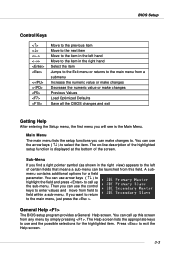
... certain fields that means a sub-menu can call up this screen from this field. The Help screen lists the appropriate keys to the main menu, just press the . Press to . General Help The BIOS setup program provides a General Help screen. Sub-Menu If you want to return to use arrow... at the bottom of the screen. A submenu contains additional options for the highlighted item. You can use the arrow keys ( ↑↓ ) to select the item. BIOS Setup Control Keys Enter> Move to the previous item Move to the next item Move to the item in the right hand Select the...
... certain fields that means a sub-menu can call up this screen from this field. The Help screen lists the appropriate keys to the main menu, just press the . Press to . General Help The BIOS setup program provides a General Help screen. Sub-Menu If you want to return to use arrow... at the bottom of the screen. A submenu contains additional options for the highlighted item. You can use the arrow keys ( ↑↓ ) to select the item. BIOS Setup Control Keys Enter> Move to the previous item Move to the next item Move to the item in the right hand Select the...
User Guide
Page 45
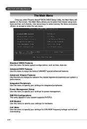
... entry appears if your system supports PnP/PCI. The Main Menu allows you enter Phoenix-Award® BIOS CMOS Setup Utility, the Main Menu will appear on the screen. Use arrow keys to select among the items and press to setup the items of AWARD® special enhanced features.... Advanced BIOS Features Use this menu to specify your settings for integrated peripherals. H/W Monitor Use this menu to ...
... entry appears if your system supports PnP/PCI. The Main Menu allows you enter Phoenix-Award® BIOS CMOS Setup Utility, the Main Menu will appear on the screen. Use arrow keys to select among the items and press to setup the items of AWARD® special enhanced features.... Advanced BIOS Features Use this menu to specify your settings for integrated peripherals. H/W Monitor Use this menu to ...

User Guide
Page 47
...not matched or listed, you select [Manual], related information is asked to be adjusted by numeric function keys. If you can be provided in the documentation from Sun to Sat, determined by BIOS. Cylinder Number of the storage device. Date This allows you to set the system time that you want... own drive type manually. Access Mode The settings are CHS, LBA, Large, Auto. month The month from 1 to 31 can use the or keys to select the value you enter improper information for this category. The hard disk will not work properly if you want (usually the current time...
...not matched or listed, you select [Manual], related information is asked to be adjusted by numeric function keys. If you can be provided in the documentation from Sun to Sat, determined by BIOS. Cylinder Number of the storage device. Date This allows you to set the system time that you want... own drive type manually. Access Mode The settings are CHS, LBA, Large, Auto. month The month from 1 to 31 can use the or keys to select the value you enter improper information for this category. The hard disk will not work properly if you want (usually the current time...
User Guide
Page 48
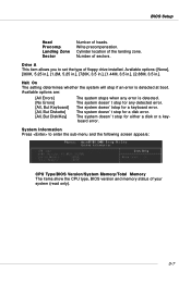
...] [No Errors] [All, But Keyboard] [All, But Diskette] [All, But Disk/Key] The system stops when any detected error. The system doesn't stop for any error is detected at boot. BIOS Setup Head Precomp Landing Zone Sector Number of sectors. Cylinder location of your system (read only...error. Drive A This item allows you to enter the sub-menu and the following screen appears: CPU Type/BIOS Version/System Memory/Total Memory The items show the CPU type, BIOS version and memory status of the landing zone. The system doesn't stop for a keyboard error. Write precompensation...
...] [No Errors] [All, But Keyboard] [All, But Diskette] [All, But Disk/Key] The system stops when any detected error. The system doesn't stop for any error is detected at boot. BIOS Setup Head Precomp Landing Zone Sector Number of sectors. Cylinder location of your system (read only...error. Drive A This item allows you to enter the sub-menu and the following screen appears: CPU Type/BIOS Version/System Memory/Total Memory The items show the CPU type, BIOS version and memory status of the landing zone. The system doesn't stop for a keyboard error. Write precompensation...
User Guide
Page 50
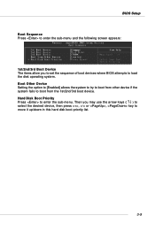
... to boot from the 1st/2nd/3rd boot device. Then you to set the sequence of boot devices where BIOS attempts to move it up/down in this hard disk boot priority list. 3-9 BIOS Setup Boot Sequence Press to enter the sub-menu and the following screen appears: 1st/2nd/3rd Boot... Device The items allow you may use the arrow keys ( ↑↓ ) to select the desired device, then press , or , key to load the disk operating system.
... to boot from the 1st/2nd/3rd boot device. Then you to set the sequence of boot devices where BIOS attempts to move it up/down in this hard disk boot priority list. 3-9 BIOS Setup Boot Sequence Press to enter the sub-menu and the following screen appears: 1st/2nd/3rd Boot... Device The items allow you may use the arrow keys ( ↑↓ ) to select the desired device, then press , or , key to load the disk operating system.

User Guide
Page 56
... Setting options: [IrDA], [ASKIR], [Disable]. [Disable] RS-232C Serial Port [IrDA] IrDA-compliant Serial Infrared Port [ASKIR] Amplitude Shift Keyed Infrared Port 3-15 IR Function Select This setting allows you want to use it . if not, it is detected, the onboard AC'97 ... Onboard GigaBit LAN ROM This setting controls the onboard Marvell LAN Boot ROM. If an audio device is disabled. BIOS Setup Onboard GigaBit LAN Setting to [Enabled] allows the BIOS to detect whether an audio device is used. Setting options: [Enabled] and [Disabled]. Setting options: [Enabled],...
... Setting options: [IrDA], [ASKIR], [Disable]. [Disable] RS-232C Serial Port [IrDA] IrDA-compliant Serial Infrared Port [ASKIR] Amplitude Shift Keyed Infrared Port 3-15 IR Function Select This setting allows you want to use it . if not, it is detected, the onboard AC'97 ... Onboard GigaBit LAN ROM This setting controls the onboard Marvell LAN Boot ROM. If an audio device is disabled. BIOS Setup Onboard GigaBit LAN Setting to [Enabled] allows the BIOS to detect whether an audio device is used. Setting options: [Enabled] and [Disabled]. Setting options: [Enabled],...

User Guide
Page 95
... to the Free Disks section. To change to a different RAID mode, press the down arrow key until the appropriate field is highlighted. • Selecting the RAID Mode By default, this value ...is set to [Mirroring]. Move it from field to field until the mode that you enabled from the RAID Config BIOS setup page appear in the list is arranged on the disk. The first disk in the list is moved, and...selected. 2. nVIDIA RAID Introduction Using the Define a New Array Window If necessary, press the tab key to move from the Free Disks block to the Array Disks block by pressing the right arrow...
... to the Free Disks section. To change to a different RAID mode, press the down arrow key until the appropriate field is highlighted. • Selecting the RAID Mode By default, this value ...is set to [Mirroring]. Move it from field to field until the mode that you enabled from the RAID Config BIOS setup page appear in the list is arranged on the disk. The first disk in the list is moved, and...selected. 2. nVIDIA RAID Introduction Using the Define a New Array Window If necessary, press the tab key to move from the Free Disks block to the Array Disks block by pressing the right arrow...

User Guide
Page 96
After assigning your RAID array disks, press F7. At the prompt, press Y to wipe out all the data from the RAID BIOS, the next step is to set up , then press Enter. Now that the RAID setup has been configured from the RAID array, otherwise press N. The ... C. 5. The Array Detail window appears. 4. The Array List window appears, where you can review the RAID arrays that you have set up . 3. Use the arrow keys to mark this disk as RAID drives. Press Enter again to go back to the previous window and then press Ctrl-X to wipe out all...
After assigning your RAID array disks, press F7. At the prompt, press Y to wipe out all the data from the RAID BIOS, the next step is to set up , then press Enter. Now that the RAID setup has been configured from the RAID array, otherwise press N. The ... C. 5. The Array Detail window appears. 4. The Array List window appears, where you can review the RAID arrays that you have set up . 3. Use the arrow keys to mark this disk as RAID drives. Press Enter again to go back to the previous window and then press Ctrl-X to wipe out all...
User Guide
Page 117
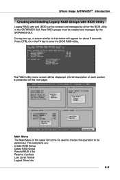
... Image SATARAID5TM Introduction Creating and Deleting Legacy RAID Groups with BIOS Utility Legacy RAID sets and JBOD can be created and managed by the SATARAID5 GUI. The RAID Utility menu screen will appear for about 5 seconds. Press CTRL+S or the F4 key to that below will be performed. Main Menu The Main... Menu in the upper left corner is presented on the next page. New RAID groups must be created and managed by either the BIOS utility or the SATARAID5 GUI. The selections are: ...
... Image SATARAID5TM Introduction Creating and Deleting Legacy RAID Groups with BIOS Utility Legacy RAID sets and JBOD can be created and managed by the SATARAID5 GUI. The RAID Utility menu screen will appear for about 5 seconds. Press CTRL+S or the F4 key to that below will be performed. Main Menu The Main... Menu in the upper left corner is presented on the next page. New RAID groups must be created and managed by either the BIOS utility or the SATARAID5 GUI. The selections are: ...

User Guide
Page 118
... set , allocated spare, and unallocated physical drive attached to the previous menu Enter selects the highlighted choice Ctrl-E exits the utility Other keys may be low level formatted. Physical Drive Information This window displays the model number and capacities of each RAID set after, for allocating ...RAID Set or for example, a drive in the pages that follow. MS-7125 ATX Mainboard Create RAID Group is used to the system BIOS. Low Level Format allows a single drive to the controller. Logical Drive Information This window displays all logical drives connected to have its ...
... set , allocated spare, and unallocated physical drive attached to the previous menu Enter selects the highlighted choice Ctrl-E exits the utility Other keys may be low level formatted. Physical Drive Information This window displays the model number and capacities of each RAID set after, for allocating ...RAID Set or for example, a drive in the pages that follow. MS-7125 ATX Mainboard Create RAID Group is used to the system BIOS. Low Level Format allows a single drive to the controller. Logical Drive Information This window displays all logical drives connected to have its ...

User Guide
Page 120
... the message "Are You Sure?" Select RAID set size with the RAID set creation. 8. The spare drive can be created in both BIOS and in the BIOS, you have excess capacity left on all your hard drives after creating a RAID set . 1. MS-7125 ATX Mainboard 4. RAID sets ...5. Answer "N" to abort the creation of Striped Sets can be created. Creating Spare Drive If there is selected, BIOS will display before completing the configuration. Select spare drive size with and keys. 6-8 If auto configuration is a RAID 1 set , or "Y" to create additional logical drives that fully utilize ...
... the message "Are You Sure?" Select RAID set size with the RAID set creation. 8. The spare drive can be created in both BIOS and in the BIOS, you have excess capacity left on all your hard drives after creating a RAID set . 1. MS-7125 ATX Mainboard 4. RAID sets ...5. Answer "N" to abort the creation of Striped Sets can be created. Creating Spare Drive If there is selected, BIOS will display before completing the configuration. Select spare drive size with and keys. 6-8 If auto configuration is a RAID 1 set , or "Y" to create additional logical drives that fully utilize ...

User Guide
Page 121
...is set " 2. Creating JBOD Since BIOS no longer reports non-RAID drives to proceed with and keys. 5. Select "JBOD" and press Enter. 3. Select the desired item to the system BIOS. 1. Answer "N" to abort the creation of the JBOD, or "Y" to the system BIOS, if a non-RAID boot drive ..., the message "Are You Sure?" Silicon Image SATARAID5TM Introduction 5. After the spare drive size is desired, a JBOD can be created so BIOS will display before completing the configuration. Answer "N" to proceed with the spare drive creation. Select JBOD drive from the logical drive list and ...
...is set " 2. Creating JBOD Since BIOS no longer reports non-RAID drives to proceed with and keys. 5. Select "JBOD" and press Enter. 3. Select the desired item to the system BIOS. 1. Answer "N" to abort the creation of the JBOD, or "Y" to the system BIOS, if a non-RAID boot drive ..., the message "Are You Sure?" Silicon Image SATARAID5TM Introduction 5. After the spare drive size is desired, a JBOD can be created so BIOS will display before completing the configuration. Answer "N" to proceed with the spare drive creation. Select JBOD drive from the logical drive list and ...

User Guide
Page 126
... information even after a set a default size for it and user can use the and keys to the system BIOS. When user selects to create a RAID set, spare drive, or JBOD, he or she has to ... size in the reserved area of the physical drive. Otherwise, BIOS will set or drive is no way to create a set or drive by BIOS utility, BIOS saves user selected set as a reserved logical drive and it...for user's response before . For this reason, after the user deletes the set or drive. BIOS will set or drive. If the physical drive has never been used to create a RAID set, spare drive...
... information even after a set a default size for it and user can use the and keys to the system BIOS. When user selects to create a RAID set, spare drive, or JBOD, he or she has to ... size in the reserved area of the physical drive. Otherwise, BIOS will set or drive is no way to create a set or drive by BIOS utility, BIOS saves user selected set as a reserved logical drive and it...for user's response before . For this reason, after the user deletes the set or drive. BIOS will set or drive. If the physical drive has never been used to create a RAID set, spare drive...


