
User Guide
Page 2
....msi.com.tw/index.php? Alternatively, please try the following help resources for FAQ, technical guide, BIOS updates, driver updates, and other countries. func=service Contact our technical staff at: http://ocss.msi.com.tw ii AMD,...user's manual, please contact your place of purchase or local distributor. We take every care in the preparation of this document is a registered trademark of American Megatrends Inc. Our products are registered trademarks of M ICRO-STAR INTERNATIONAL. AMI® is the intellectual property of International Business Machines Corporation. Visit the MSI...
....msi.com.tw/index.php? Alternatively, please try the following help resources for FAQ, technical guide, BIOS updates, driver updates, and other countries. func=service Contact our technical staff at: http://ocss.msi.com.tw ii AMD,...user's manual, please contact your place of purchase or local distributor. We take every care in the preparation of this document is a registered trademark of American Megatrends Inc. Our products are registered trademarks of M ICRO-STAR INTERNATIONAL. AMI® is the intellectual property of International Business Machines Corporation. Visit the MSI...
User Guide
Page 8
...Components Guide 2-2 CPU (Central Processing Unit 2-3 Memory ...2-6 Power Supply ...2-8 Back Panel ...2-9 Connectors ...2-11 Buttons ...2-18 Switc h ...2-19 Slots ...2-20 Chapter 3 BIOS Setup 3-1 Entering Setup ...3-2 The Main Menu ...3-4 Standard CMOS Features 3-6 Advanced BIOS Features 3-9 Integrated Peripherals 3-12 Power Management Setup 3-14 H/W Monitor ...3-17 Green Power ...3-18 BIOS Setting Password 3-19 Cell Menu ...3-20 User Settings ...3-25 Load Fail-Safe/Optimized Defaults 3-26 Appendix A Realtek Audio A-1 Installing the Realtek HD Audio Driver A-2 Software Configuration...
...Components Guide 2-2 CPU (Central Processing Unit 2-3 Memory ...2-6 Power Supply ...2-8 Back Panel ...2-9 Connectors ...2-11 Buttons ...2-18 Switc h ...2-19 Slots ...2-20 Chapter 3 BIOS Setup 3-1 Entering Setup ...3-2 The Main Menu ...3-4 Standard CMOS Features 3-6 Advanced BIOS Features 3-9 Integrated Peripherals 3-12 Power Management Setup 3-14 H/W Monitor ...3-17 Green Power ...3-18 BIOS Setting Password 3-19 Cell Menu ...3-20 User Settings ...3-25 Load Fail-Safe/Optimized Defaults 3-26 Appendix A Realtek Audio A-1 Installing the Realtek HD Audio Driver A-2 Software Configuration...
User Guide
Page 11
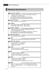
... Max) - 4 DDR3 DIMMs (240pin/1.5V) (For more information on compatible components, please visit ht t p: / / global. Hyper Transport 3.0 up to 400Mbps - DDR3 SDRAM 1Gbit (optional) LAN - Supports up to 3 Gb/s RAID - t w / index. Transfer rate is up to 8-channel audio with jack sensing IDE - 1 IDE port by SB710 / SB750 - Supports Ultra DMA 66/100/133 mode - c om . North Bridge: AMD® 790GX / 780G chipset - Supports PIO, Bus Master operation mode SATA - 5 SATA II ports...
... Max) - 4 DDR3 DIMMs (240pin/1.5V) (For more information on compatible components, please visit ht t p: / / global. Hyper Transport 3.0 up to 400Mbps - DDR3 SDRAM 1Gbit (optional) LAN - Supports up to 3 Gb/s RAID - t w / index. Transfer rate is up to 8-channel audio with jack sensing IDE - 1 IDE port by SB710 / SB750 - Supports Ultra DMA 66/100/133 mode - c om . North Bridge: AMD® 790GX / 780G chipset - Supports PIO, Bus Master operation mode SATA - 5 SATA II ports...

User Guide
Page 12
... port - 1 VGA port - 1 DVI-D port - 1 HDMI port - 1 1394 port (optional) - 6 USB 2.0 ports - 1 eSATA port - 1 LAN jack - 6 flexible audio jacks On-Board Pinheaders/ Connectors - 3 USB 2.0 pinheaders - 1 IEEE1394 pinheader (optional) - 1 SPDIF out connector - 1 CD-In connector - 1 Front Panel Audio pinheader - 1 Chassis Intrusion Switch pinheader - 1 Serial port connector - 1 TPM pinheader (optional) - 1 OC switch - 1 Power LED Button - 1 Reset LED Button - 1 Clear CMOS Button Slots For 790GX - 1 PCI Express x16 slot supports up to PCI Express x16 speed. Getting Started Floppy - 1 floppy port...
... port - 1 VGA port - 1 DVI-D port - 1 HDMI port - 1 1394 port (optional) - 6 USB 2.0 ports - 1 eSATA port - 1 LAN jack - 6 flexible audio jacks On-Board Pinheaders/ Connectors - 3 USB 2.0 pinheaders - 1 IEEE1394 pinheader (optional) - 1 SPDIF out connector - 1 CD-In connector - 1 Front Panel Audio pinheader - 1 Chassis Intrusion Switch pinheader - 1 Serial port connector - 1 TPM pinheader (optional) - 1 OC switch - 1 Power LED Button - 1 Reset LED Button - 1 Clear CMOS Button Slots For 790GX - 1 PCI Express x16 slot supports up to PCI Express x16 speed. Getting Started Floppy - 1 floppy port...

User Guide
Page 22
...-pin ATX power supply as you like. To connect the ATX 24-pin power supply, make sure the plug of the mainboard. 2. If you to connect an ATX 24-pin power supply. You may use the 20-pin ATX power supply, please plug your power supply along with pin 1 & pin 13 (refer to the CPU. There is used to provide power to the image at the right hand). Make sure that all the connectors are connected to proper ATX power supplies to avoid wrong installation...
...-pin ATX power supply as you like. To connect the ATX 24-pin power supply, make sure the plug of the mainboard. 2. If you to connect an ATX 24-pin power supply. You may use the 20-pin ATX power supply, please plug your power supply along with pin 1 & pin 13 (refer to the CPU. There is used to provide power to the image at the right hand). Make sure that all the connectors are connected to proper ATX power supplies to avoid wrong installation...

User Guide
Page 23
... support IDE mode) 2-9 It provides a high-speed digital interconnection between the computer and its display device. VGA Port The DB15-pin female connector is for attaching the eSATA external hard drive. eSATA Port The eSATA port is an all-digital audio/video interface capable of transmitting uncompressed streams. HDMI supports all TV format, including standard, enhanced, or high-definition video, plus multi-channel digital audio on a single cable. 1394 Port (optional) The IEEE1394 port on the back panel...
... support IDE mode) 2-9 It provides a high-speed digital interconnection between the computer and its display device. VGA Port The DB15-pin female connector is for attaching the eSATA external hard drive. eSATA Port The eSATA port is an all-digital audio/video interface capable of transmitting uncompressed streams. HDMI supports all TV format, including standard, enhanced, or high-definition video, plus multi-channel digital audio on a single cable. 1394 Port (optional) The IEEE1394 port on the back panel...

User Guide
Page 25
Refer to master / slave mode by the vendors for jumper setting instructions. 2-11 Hardware Setup Connectors Floppy Disk Drive Connector: FDD1 This connector supports 360KB, 720KB, 1.2MB, 1.44MB or 2.88MB floppy disk drive. IDE1 Important If you install two IDE devices on the same cable, you must configure the drives separately to IDE device's documentation supplied by setting jumpers. FDD1 IDE Connector: IDE1 This connector supports IDE hard disk drives, optical disk drives and other IDE devices.
Refer to master / slave mode by the vendors for jumper setting instructions. 2-11 Hardware Setup Connectors Floppy Disk Drive Connector: FDD1 This connector supports 360KB, 720KB, 1.2MB, 1.44MB or 2.88MB floppy disk drive. IDE1 Important If you install two IDE devices on the same cable, you must configure the drives separately to IDE device's documentation supplied by setting jumpers. FDD1 IDE Connector: IDE1 This connector supports IDE hard disk drives, optical disk drives and other IDE devices.

User Guide
Page 27
... BIOS utility and clear the record. 1 CINTRU 2 GND JCI1 2-13 If the mainboard has a System Hardware Monitor chipset on the screen. CPUFAN1 supports fan control. GND +1 2V SE NS OR GND +12V SENSOR Control CPUFAN1 SYSFAN1/2 NC +12V GND SYSFAN3 Important 1. Fan/heatsink with +12V. SYSFAN1/2 support fan control, too. Hardware Setup Fan Power Connectors: CPUFAN1, SYSFAN1~3 The fan power connectors support system cooling fan with 3 or 4 pins are both available for CPUFAN1. 4. Chassis Intrusion Connector: JCI1 This connector connects...
... BIOS utility and clear the record. 1 CINTRU 2 GND JCI1 2-13 If the mainboard has a System Hardware Monitor chipset on the screen. CPUFAN1 supports fan control. GND +1 2V SE NS OR GND +12V SENSOR Control CPUFAN1 SYSFAN1/2 NC +12V GND SYSFAN3 Important 1. Fan/heatsink with +12V. SYSFAN1/2 support fan control, too. Hardware Setup Fan Power Connectors: CPUFAN1, SYSFAN1~3 The fan power connectors support system cooling fan with 3 or 4 pins are both available for CPUFAN1. 4. Chassis Intrusion Connector: JCI1 This connector connects...
User Guide
Page 35
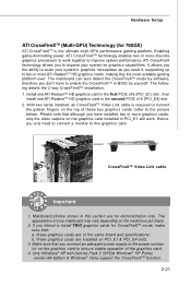
... more graphics cards, only the video outputs on the graphics card installed in BIOS by software, therefore you to two or more discrete graphics processors to work . W ith two cards installed, an CrossFireXTM Video Link cable is the ultimate multi-GPU performance gaming platform. Mainboard photos shown in the second PCIE x16 (PCI_E4) slot. 2. Make sure that : a. Hardware Setup ATI CrossFireXTM (Multi-GPU) Technology (for 790GX) ATI CrossFireXTM is required to connect...
... more graphics cards, only the video outputs on the graphics card installed in BIOS by software, therefore you to two or more discrete graphics processors to work . W ith two cards installed, an CrossFireXTM Video Link cable is the ultimate multi-GPU performance gaming platform. Mainboard photos shown in the second PCIE x16 (PCI_E4) slot. 2. Make sure that : a. Hardware Setup ATI CrossFireXTM (Multi-GPU) Technology (for 790GX) ATI CrossFireXTM is required to connect...

User Guide
Page 39
... connected to configure any necessary hardware or software settings for the expansion card, such as follows: PCI Slot 1 PCI Slot 2 Order 1 INT A# INT B# Order 2 INT B# INT C# Order 3 INT C# INT D# Order 4 INT D# INT A# 2-25 Hardware Setup PCI (Peripheral Component Interconnect) Slot The PCI slot supports LAN cards, SCSI cards, USB cards, and other add-on cards that you unplug the power supply first. Meanwhile, read the documentation for the expansion card to the PCI bus pins as jumpers, switches or BIOS configuration...
... connected to configure any necessary hardware or software settings for the expansion card, such as follows: PCI Slot 1 PCI Slot 2 Order 1 INT A# INT B# Order 2 INT B# INT C# Order 3 INT C# INT D# Order 4 INT D# INT A# 2-25 Hardware Setup PCI (Peripheral Component Interconnect) Slot The PCI slot supports LAN cards, SCSI cards, USB cards, and other add-on cards that you unplug the power supply first. Meanwhile, read the documentation for the expansion card to the PCI bus pins as jumpers, switches or BIOS configuration...

User Guide
Page 46
... fail to a safe place before the hard disk becomes offline. Floppy A This item allows you to activate the S.M.A.R.T. (Self-Monitoring Analysis & Reporting Technology) capability for the hard disks. S.M.A.R.T is a utility that you to enable or disable the LBA Mode. Hard Disk S.M.A.R.T. DM A M ode Select DMA Mode. BIOS Setup Device/ Vender/ Size It will showing the device information that monitors your disk status to predict hard disk failure. LBA/Large M ode This allows you connected to the IDE/SATA connector.
... fail to a safe place before the hard disk becomes offline. Floppy A This item allows you to activate the S.M.A.R.T. (Self-Monitoring Analysis & Reporting Technology) capability for the hard disks. S.M.A.R.T is a utility that you to enable or disable the LBA Mode. Hard Disk S.M.A.R.T. DM A M ode Select DMA Mode. BIOS Setup Device/ Vender/ Size It will showing the device information that monitors your disk status to predict hard disk failure. LBA/Large M ode This allows you connected to the IDE/SATA connector.

User Guide
Page 48
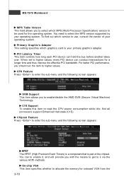
... Screen Logo Display This item enables this system to update the BIOS. W hen enabled, the BIOS' data cannot be changed when attempting to [On] will allow users to disable this function at boot. The only time when you 'll need to disable it is powered on. Setting to [Off] will turn on the Num Lock key when the system is when you should enable this Flash BIOS Protection function. Enabling...
... Screen Logo Display This item enables this system to update the BIOS. W hen enabled, the BIOS' data cannot be changed when attempting to [On] will allow users to disable this function at boot. The only time when you 'll need to disable it is powered on. Setting to [Off] will turn on the Num Lock key when the system is when you should enable this Flash BIOS Protection function. Enabling...
User Guide
Page 49
... get to enable/disable the AMD SVM (Secure Virtual Machine) Tec hn ology. Not all porcessors support Enhanced Halt state (C1E). On-chip VGA This item specifies whether to higher values, every PCI device can hold the bus before another takes over. To find out which version to higher values. PCI Latency Timer This item controls how long each PCI device can conduct transactions for onboard VGA from...
... get to enable/disable the AMD SVM (Secure Virtual Machine) Tec hn ology. Not all porcessors support Enhanced Halt state (C1E). On-chip VGA This item specifies whether to higher values, every PCI device can hold the bus before another takes over. To find out which version to higher values. PCI Latency Timer This item controls how long each PCI device can conduct transactions for onboard VGA from...
User Guide
Page 51
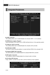
...enable/disable the onboard IEEE1394 controller. Onboard IEEE1394 Controller This item allows you to use a USB-interfaced device in the operating system. Onboard LAN Controller This setting allows you to enter the sub-menu and the following screen appears: 3-12 LAN Option ROM This item is used to decide whether to enable/disable the onboard USB 1.1/ 2.0 controller. HD Audio Controller This setting is used to enable/disable the onboard audio controller. On-Chip ATA Devices Press to enable/disable the onboard LAN controller. MS-7576 Mainboard Integrated Peripherals USB Controller...
...enable/disable the onboard IEEE1394 controller. Onboard IEEE1394 Controller This item allows you to use a USB-interfaced device in the operating system. Onboard LAN Controller This setting allows you to enter the sub-menu and the following screen appears: 3-12 LAN Option ROM This item is used to decide whether to enable/disable the onboard USB 1.1/ 2.0 controller. HD Audio Controller This setting is used to enable/disable the onboard audio controller. On-Chip ATA Devices Press to enable/disable the onboard LAN controller. MS-7576 Mainboard Integrated Peripherals USB Controller...

User Guide
Page 52
RAID Mode This item is used PCI busmastering for reading/ writing to enter the sub-menu and the following screen appears: COM Port 1 Select an address and corresponding interrupt for SATA connectors. OnChip SATA Controller This item allows users to select mode for the serial port. 3-13 I/O Devices Configuration Press to IDE drives. BIOS Setup PCI IDE BusMaster This item allows you to enable/ disable BIOS to used to enable or disable the SATA controller.
RAID Mode This item is used PCI busmastering for reading/ writing to enter the sub-menu and the following screen appears: COM Port 1 Select an address and corresponding interrupt for SATA connectors. OnChip SATA Controller This item allows users to select mode for the serial port. 3-13 I/O Devices Configuration Press to IDE drives. BIOS Setup PCI IDE BusMaster This item allows you to enable/ disable BIOS to used to enable or disable the SATA controller.

User Guide
Page 56
H/W Monitor BIOS Setup Chassis Intrusion The field enables or disables the feature of speed for cooling down automaticlly . SYS FAN1/2 Control This item allows users to [Enabled] later. To clear the warning message, set the field to keep it with in a specific range. PC Health Status CPU/ System Temperature, CPU FAN/ SYS FAN1/ SYS FAN2 Speed, CPU Vcore, 3.3V, 5V, 12V These items display the current status of all fans' speeds. 3-17 You...
H/W Monitor BIOS Setup Chassis Intrusion The field enables or disables the feature of speed for cooling down automaticlly . SYS FAN1/2 Control This item allows users to [Enabled] later. To clear the warning message, set the field to keep it with in a specific range. PC Health Status CPU/ System Temperature, CPU FAN/ SYS FAN1/ SYS FAN2 Speed, CPU Vcore, 3.3V, 5V, 12V These items display the current status of all fans' speeds. 3-17 You...

User Guide
Page 62
...CPU, Memory and chipset. For the most suitable Spread Spectrum value, please consult your overclocked processor to lock up . BIOS Setup HT Incoming Link Width This field specifies the operation width of the outgoing link. Adjust PCI-E Frequency (MHz) This field allows you do not have any EMI problem, leave the setting at Disabled... problem, leave the setting at [Disabled] for EMI reduction. If you are plagued by EMI, set to set to [Enabled], the system will remove (turn off) clocks from empty DRAM/ PCI slots to [Auto], the system will become less stable. Remember to disable...
...CPU, Memory and chipset. For the most suitable Spread Spectrum value, please consult your overclocked processor to lock up . BIOS Setup HT Incoming Link Width This field specifies the operation width of the outgoing link. Adjust PCI-E Frequency (MHz) This field allows you do not have any EMI problem, leave the setting at Disabled... problem, leave the setting at [Disabled] for EMI reduction. If you are plagued by EMI, set to set to [Enabled], the system will remove (turn off) clocks from empty DRAM/ PCI slots to [Auto], the system will become less stable. Remember to disable...

User Guide
Page 67
... HD Audio Configuration software utility is under continuous update to function properly before installing the driver. Hence, the program screens shown here in different operating systems. 1. MS-7576 Mainboard Installing the Realtek HD Audio Driver You need to install the driver for reference only. The setup screen will automatically appear. 2. Insert the MSI DVD into the DVD-ROM drive. Follow the procedures described below to install the drivers for different operating systems. Installation for Windows...
... HD Audio Configuration software utility is under continuous update to function properly before installing the driver. Hence, the program screens shown here in different operating systems. 1. MS-7576 Mainboard Installing the Realtek HD Audio Driver You need to install the driver for reference only. The setup screen will automatically appear. 2. Insert the MSI DVD into the DVD-ROM drive. Follow the procedures described below to install the drivers for different operating systems. Installation for Windows...

User Guide
Page 103
... the Setup screen. 3. And then, follow the instruction below to make a SATA RAID driver for RAID controller is formatted, and W indows setup starts copying files. Insert the floppy that you have successfully installed the RAID driver, and W indows setup should be shown a list of available SCSI Adapters. 6. Insert the MSI DVD into the DVD-ROM drive. 2. Copy all the contents in the floppy drive until the system reboots itself. Select the compatible RAID controller for bootable RAID Array...
... the Setup screen. 3. And then, follow the instruction below to make a SATA RAID driver for RAID controller is formatted, and W indows setup starts copying files. Insert the floppy that you have successfully installed the RAID driver, and W indows setup should be shown a list of available SCSI Adapters. 6. Insert the MSI DVD into the DVD-ROM drive. 2. Copy all the contents in the floppy drive until the system reboots itself. Select the compatible RAID controller for bootable RAID Array...

User Guide
Page 104
The DVD will auto-run and the setup screen will be automatically installed. Insert the MSI DVD into the DVD-ROM drive. 2. C-9 The driver will appear. 3. Under the Driver tab, click on ATI System Driver by your need. SATA RAID Installing the RAID Driver Under Windows (for Non-bootable RAID Array) 1. Important You must install the RAID driver to enable RAID. The ATI System Driver includes RAID Driver. 4.
The DVD will auto-run and the setup screen will be automatically installed. Insert the MSI DVD into the DVD-ROM drive. 2. C-9 The driver will appear. 3. Under the Driver tab, click on ATI System Driver by your need. SATA RAID Installing the RAID Driver Under Windows (for Non-bootable RAID Array) 1. Important You must install the RAID driver to enable RAID. The ATI System Driver includes RAID Driver. 4.


