User Guide
Page 4
... by turning the equipment off and on a circuit different from that to which can radiate radio frequency energy and, if not installed and used in accordance with the emission limits. power cord, if any, must accept any interference received, including interference that interference...LANOTICE D'INSTALLATIONAVANT DE RACCORDER AU RESEAU. These limits are designed to provide reasonable protection against harmful interference in a particular installation. Operation is subject to the following two conditions: (1) this device may not cause harmful interference, and (2) this equipment...
... by turning the equipment off and on a circuit different from that to which can radiate radio frequency energy and, if not installed and used in accordance with the emission limits. power cord, if any, must accept any interference received, including interference that interference...LANOTICE D'INSTALLATIONAVANT DE RACCORDER AU RESEAU. These limits are designed to provide reasonable protection against harmful interference in a particular installation. Operation is subject to the following two conditions: (1) this device may not cause harmful interference, and (2) this equipment...
User Guide
Page 8
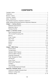
Hardware Setup 2-1 Quick Components Guide 2-2 CPU (Central Processing Unit 2-3 Memory ...2-6 Power Supply ...2-8 Back Panel ...2-9 Connectors ...2-11 Buttons ...2-18 Switc h ...2-19 Slots ...2-20 Chapter 3 BIOS Setup 3-1 Entering Setup...17 Green Power ...3-18 BIOS Setting Password 3-19 Cell Menu ...3-20 User Settings ...3-25 Load Fail-Safe/Optimized Defaults 3-26 Appendix A Realtek Audio A-1 Installing the Realtek HD Audio Driver A-2 Software Configuration A-4 Hardware Setup A-19 viii CONTENTS Copyright Notice ...ii Trademarks ...ii Revision History ...ii Technical Support ...ii...
Hardware Setup 2-1 Quick Components Guide 2-2 CPU (Central Processing Unit 2-3 Memory ...2-6 Power Supply ...2-8 Back Panel ...2-9 Connectors ...2-11 Buttons ...2-18 Switc h ...2-19 Slots ...2-20 Chapter 3 BIOS Setup 3-1 Entering Setup...17 Green Power ...3-18 BIOS Setting Password 3-19 Cell Menu ...3-20 User Settings ...3-25 Load Fail-Safe/Optimized Defaults 3-26 Appendix A Realtek Audio A-1 Installing the Realtek HD Audio Driver A-2 Software Configuration A-4 Hardware Setup A-19 viii CONTENTS Copyright Notice ...ii Trademarks ...ii Revision History ...ii Technical Support ...ii...

User Guide
Page 15
Use a grounded wrist strap before handling computer components. While doing the installation, be careful in the wrong orientation, the components will not work properly. For some components, if you with the information about hardware setup procedures. Static electricity may damage the components. 2-1 Hardware Setup Chapter 2 Hardware Setup This chapter provides you install in holding the components and follow the installation procedures.
Use a grounded wrist strap before handling computer components. While doing the installation, be careful in the wrong orientation, the components will not work properly. For some components, if you with the information about hardware setup procedures. Static electricity may damage the components. 2-1 Hardware Setup Chapter 2 Hardware Setup This chapter provides you install in holding the components and follow the installation procedures.

User Guide
Page 17
... inadequate operation or beyond product specifications is designed to support overclocking. For the latest information about CPU, please visit http://global.msi.com.tw/index. Overclocking This mainboard is not recommended. However, please make sure to install the cooler to prevent overheating. Any attempt to operate beyond product specifications. 2-3 We do not have...
... inadequate operation or beyond product specifications is designed to support overclocking. For the latest information about CPU, please visit http://global.msi.com.tw/index. Overclocking This mainboard is not recommended. However, please make sure to install the cooler to prevent overheating. Any attempt to operate beyond product specifications. 2-3 We do not have...

User Guide
Page 18
...in the correct orientation. 3. Please note that any violation of your mainboard. 4. W rong installation will cause the damage of the correct installation procedures may cause permanent damages to prevent overheating. The CPU can not be completely embedded into the socket and can only fit in the picture. If ... Make sure to raise the lever up to apply some thermal paste on CPU before installing the heat sink/cooler fan for the gold arrow of the CPU to install the CPU & cooler correctly. As the CPU is likely to move while the lever is properly and completely embedded into ...
...in the correct orientation. 3. Please note that any violation of your mainboard. 4. W rong installation will cause the damage of the correct installation procedures may cause permanent damages to prevent overheating. The CPU can not be completely embedded into the socket and can only fit in the picture. If ... Make sure to raise the lever up to apply some thermal paste on CPU before installing the heat sink/cooler fan for the gold arrow of the CPU to install the CPU & cooler correctly. As the CPU is likely to move while the lever is properly and completely embedded into ...

User Guide
Page 19
... section are for Socket AM2+ CPUs only. Hardware Setup 5. Position the cooling set on the top of the retention mechanism. Attach the CPU Fan cable to keep an eye on your mainboard may vary depending on the mainboard. While disconnecting the Safety Hook from the fixed bolt,...cooling set onto the retention mechanism. Locate the Fix Lever and lift up it is necessary to the CPU fan connector on the model you purchase. 2. Important 1. Fasten down the other end of the cooler installation for demonstration of the clip to hook first. 6. Then press down the lever. 8.
... section are for Socket AM2+ CPUs only. Hardware Setup 5. Position the cooling set on the top of the retention mechanism. Attach the CPU Fan cable to keep an eye on your mainboard may vary depending on the mainboard. While disconnecting the Safety Hook from the fixed bolt,...cooling set onto the retention mechanism. Locate the Fix Lever and lift up it is necessary to the CPU fan connector on the model you purchase. 2. Important 1. Fasten down the other end of the cooler installation for demonstration of the clip to hook first. 6. Then press down the lever. 8.
User Guide
Page 20
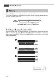
For more information on compatible components, please visit http://global.msi.com. Please refer to the following illustrations for installing memory modules. Channel B in SKYBLUE; MS-7576 Mainboard Memory These DIMM slots are used for population rules under Dual-Channel mode. 1 DIMM1 DIMM2 DIMM3 DIMM4 2 ...
For more information on compatible components, please visit http://global.msi.com. Please refer to the following illustrations for installing memory modules. Channel B in SKYBLUE; MS-7576 Mainboard Memory These DIMM slots are used for population rules under Dual-Channel mode. 1 DIMM1 DIMM2 DIMM3 DIMM4 2 ...

User Guide
Page 21
...right orientation. 2. Volt Notch Important - DDR3 memory modules are not interchangeable with DDR2 and the DDR3 standard is properly seated. You should always install DDR3 memory modules in the DIMM slot. 3. The plastic clip at the sides. In dual-channel mode, make sure that you... DDR DIMMs. - The memory module has only one notch on the memory module is properly inserted in the DDR3 DIMM slots. - Hardware Setup Installing Memory Modules 1. Then push it in until the golden finger on the center and will automatically close when the memory module is not backwards compatible....
...right orientation. 2. Volt Notch Important - DDR3 memory modules are not interchangeable with DDR2 and the DDR3 standard is properly seated. You should always install DDR3 memory modules in the DIMM slot. 3. The plastic clip at the sides. In dual-channel mode, make sure that you... DDR DIMMs. - The memory module has only one notch on the memory module is properly inserted in the DDR3 DIMM slots. - Hardware Setup Installing Memory Modules 1. Then push it in until the golden finger on the center and will automatically close when the memory module is not backwards compatible....

User Guide
Page 22
Then push down the power supply firmly into the connector. There is also a foolproof design on pin 11, 12, 23 & 24 to the CPU. If you'd like . PWR1 3 4 1 2 Pin Definition PIN SIGNAL 1 GND 2 GND 3 12V 4 12V pin 13 pin 12 Important 1. Make sure that all the connectors are aligned. ... 11 +12V 12 +3.3V 23 +5V 24 GND ATX 4-Pin Power Connector: PWR1 This 4-pin power connector is used to provide power to avoid wrong installation. You may use the 20-pin ATX power supply as you like to use the 20-pin ATX power supply, please plug your power supply...
Then push down the power supply firmly into the connector. There is also a foolproof design on pin 11, 12, 23 & 24 to the CPU. If you'd like . PWR1 3 4 1 2 Pin Definition PIN SIGNAL 1 GND 2 GND 3 12V 4 12V pin 13 pin 12 Important 1. Make sure that all the connectors are aligned. ... 11 +12V 12 +3.3V 23 +5V 24 GND ATX 4-Pin Power Connector: PWR1 This 4-pin power connector is used to provide power to avoid wrong installation. You may use the 20-pin ATX power supply as you like to use the 20-pin ATX power supply, please plug your power supply...

User Guide
Page 25
FDD1 IDE Connector: IDE1 This connector supports IDE hard disk drives, optical disk drives and other IDE devices. Hardware Setup Connectors Floppy Disk Drive Connector: FDD1 This connector supports 360KB, 720KB, 1.2MB, 1.44MB or 2.88MB floppy disk drive. IDE1 Important If you install two IDE devices on the same cable, you must configure the drives separately to IDE device's documentation supplied by setting jumpers. Refer to master / slave mode by the vendors for jumper setting instructions. 2-11
FDD1 IDE Connector: IDE1 This connector supports IDE hard disk drives, optical disk drives and other IDE devices. Hardware Setup Connectors Floppy Disk Drive Connector: FDD1 This connector supports 360KB, 720KB, 1.2MB, 1.44MB or 2.88MB floppy disk drive. IDE1 Important If you install two IDE devices on the same cable, you must configure the drives separately to IDE device's documentation supplied by setting jumpers. Refer to master / slave mode by the vendors for jumper setting instructions. 2-11

User Guide
Page 27
.... To clear the warning, you must enter the BIOS utility and clear the record. 1 CINTRU 2 GND JCI1 2-13 You may select how percentage of the CPU fan control. Hardware Setup Fan Power Connectors: CPUFAN1, SYSFAN1~3 The fan power connectors support system cooling fan with 3 or 4 pins are both available for CPUFAN1... control the these fan speed according to GND. CPUFAN1 supports fan control. If the mainboard has a System Hardware Monitor chipset on the screen. You can install Overclocking Center utility that the red wire is the positive and should be connected to the actual...
.... To clear the warning, you must enter the BIOS utility and clear the record. 1 CINTRU 2 GND JCI1 2-13 You may select how percentage of the CPU fan control. Hardware Setup Fan Power Connectors: CPUFAN1, SYSFAN1~3 The fan power connectors support system cooling fan with 3 or 4 pins are both available for CPUFAN1... control the these fan speed according to GND. CPUFAN1 supports fan control. If the mainboard has a System Hardware Monitor chipset on the screen. You can install Overclocking Center utility that the red wire is the positive and should be connected to the actual...
User Guide
Page 35
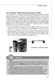
...depending on the graphics card to ensure stable operation of the same brand and specifications; The following details the 2-way CrossFireXTM installation. 1. The appearance of your system's graphics horsepower as you need to connect a monitor to this graphics card. Make ...install TWO graphics cards for CrossFireXTM mode, make sure that: a. Mainboard photos shown in PCI_E1 will work together to enable the CrossFireXTM in the second PCIE x16 (PCI_E4) slot. 2. these two graphics cards (refer to the picture below). Hardware Setup ATI CrossFireXTM (Multi-GPU) Technology (for 790GX...
...depending on the graphics card to ensure stable operation of the same brand and specifications; The following details the 2-way CrossFireXTM installation. 1. The appearance of your system's graphics horsepower as you need to connect a monitor to this graphics card. Make ...install TWO graphics cards for CrossFireXTM mode, make sure that: a. Mainboard photos shown in PCI_E1 will work together to enable the CrossFireXTM in the second PCIE x16 (PCI_E4) slot. 2. these two graphics cards (refer to the picture below). Hardware Setup ATI CrossFireXTM (Multi-GPU) Technology (for 790GX...
User Guide
Page 36
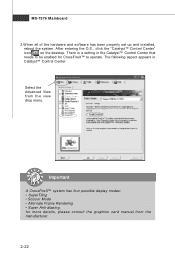
... Mode • Alternate Frame Rendering • Super Anti-aliasing. MS-7576 Mainboard 3.W hen all of the hardware and software has been properly set up and installed, reboot the system. for CrossFireX™ to be enabled for more details, please consult the graphics card manual from the view drop menu.
... Mode • Alternate Frame Rendering • Super Anti-aliasing. MS-7576 Mainboard 3.W hen all of the hardware and software has been properly set up and installed, reboot the system. for CrossFireX™ to be enabled for more details, please consult the graphics card manual from the view drop menu.

User Guide
Page 37
Graphic card based on the system and install the driver that supports Hybrid CrossFireX technology. After then, power on an ATI RadeonTM HD 2400 Series2, ATI RadeonTM HD 3400 Series or ATI Mobility ... following aspect appears in the System Tray. Hardware Setup Hybrid CrossFireXTM Technology (for 780G) Hybrid CrossFireXTM technology brings multi-GPU performance capabilities by enabling an AMD 780 integrated graphics processor and a discrete graphics processor to operate simultaneously with the Vista operating system. 2. Enabling Hybrid CrossFireXTM Technology Power off the system and...
Graphic card based on the system and install the driver that supports Hybrid CrossFireX technology. After then, power on an ATI RadeonTM HD 2400 Series2, ATI RadeonTM HD 3400 Series or ATI Mobility ... following aspect appears in the System Tray. Hardware Setup Hybrid CrossFireXTM Technology (for 780G) Hybrid CrossFireXTM technology brings multi-GPU performance capabilities by enabling an AMD 780 integrated graphics processor and a discrete graphics processor to operate simultaneously with the Vista operating system. 2. Enabling Hybrid CrossFireXTM Technology Power off the system and...

User Guide
Page 46
... & Reporting Technology) capability for the hard disks. DM A M ode Select DMA Mode. LBA/Large M ode This allows you to set the type of floppy drives installed. 3-7 This allows you connected to the IDE/SATA connector. Setting to Auto enables LBA mode if the device supports it and the devices is not...
... & Reporting Technology) capability for the hard disks. DM A M ode Select DMA Mode. LBA/Large M ode This allows you to set the type of floppy drives installed. 3-7 This allows you connected to the IDE/SATA connector. Setting to Auto enables LBA mode if the device supports it and the devices is not...

User Guide
Page 67
...Drivers. Click here Important The HD Audio Configuration software utility is under continuous update to enhance audio applications. Insert the MSI DVD into the DVD-ROM drive. Hence, the program screens shown here in different operating systems. 1. The following ... channel audio operations. Follow the procedures described below to install the drivers for different operating systems. Installation for Windows XP /Vista For W indows® XP, you must install W indows® XP Service Pack1 or later before you install the drivers in this section may be slightly different from...
...Drivers. Click here Important The HD Audio Configuration software utility is under continuous update to enhance audio applications. Insert the MSI DVD into the DVD-ROM drive. Hence, the program screens shown here in different operating systems. 1. The following ... channel audio operations. Follow the procedures described below to install the drivers for different operating systems. Installation for Windows XP /Vista For W indows® XP, you must install W indows® XP Service Pack1 or later before you install the drivers in this section may be slightly different from...

User Guide
Page 68
Click Finish to install the Realtek High Definition Audio Driver. 4. Click here Select this option A-3 Click Next to restart the system. Realtek Audio 3.
Click Finish to install the Realtek High Definition Audio Driver. 4. Click here Select this option A-3 Click Next to restart the system. Realtek Audio 3.

User Guide
Page 69
Click the audio icon from the system tray at the lower-right corner of the screen to enable the audio driver by clicking the Realtek HD Audio M anager from the Control Panel. Double click a A-4 channel audio feature now. or 8- It is also available to activate the HD Audio Configuration. MS-7576 Mainboard Software Configuration After installing the audio driver, you are able to use the 2-, 4-, 6-
Click the audio icon from the system tray at the lower-right corner of the screen to enable the audio driver by clicking the Realtek HD Audio M anager from the Control Panel. Double click a A-4 channel audio feature now. or 8- It is also available to activate the HD Audio Configuration. MS-7576 Mainboard Software Configuration After installing the audio driver, you are able to use the 2-, 4-, 6-

User Guide
Page 87
Or, the mainboard will support 5.1 channel audio-out only. a A-22 MS-7576 Mainboard n 8-Channel Mode for 8-Speaker Output 1 4 2 5 3 6 8-Channel Analog Audio Output 1 Line In 2 Line Out (Front channels) 3 MIC 4 Line Out (Rear channels) 5 Line Out (Center and Subwoofer channel) 6 Line Out (Side channels) Important To enable 7.1 channel audio-out function on Vista operating system, you have to install the Realtek Audio Driver.
Or, the mainboard will support 5.1 channel audio-out only. a A-22 MS-7576 Mainboard n 8-Channel Mode for 8-Speaker Output 1 4 2 5 3 6 8-Channel Analog Audio Output 1 Line In 2 Line Out (Front channels) 3 MIC 4 Line Out (Rear channels) 5 Line Out (Center and Subwoofer channel) 6 Line Out (Side channels) Important To enable 7.1 channel audio-out function on Vista operating system, you have to install the Realtek Audio Driver.

User Guide
Page 88
DotNet Frame Work 2.0 B-1 Before you install the Overclocking Center, please make sure the system has meet the following requirements: 1. 256MB system memory. 2. Operation system: W indows XP or up. 4. DVD-ROM drive for software installation. 3. Overclocking Center Appendix B Overclocking Center Overclocking Center, the most useful and powerful utility that MSI has spent much research and efforts to develop, helps users to monitor or configure the hardware status of MSI Motherboard in windows, such as CPU clock, voltage, fan speed and temperature.
DotNet Frame Work 2.0 B-1 Before you install the Overclocking Center, please make sure the system has meet the following requirements: 1. 256MB system memory. 2. Operation system: W indows XP or up. 4. DVD-ROM drive for software installation. 3. Overclocking Center Appendix B Overclocking Center Overclocking Center, the most useful and powerful utility that MSI has spent much research and efforts to develop, helps users to monitor or configure the hardware status of MSI Motherboard in windows, such as CPU clock, voltage, fan speed and temperature.


