
User Guide
Page 10
Getting Started Chapter 1 Getting Started Thank you for optimal system efficiency. Designed to fit the advanced 64bit AMD Phenom II processor, the 790GX-G65 Series deliver a high performance and professional desktop platform solution. 1-1 The 790GX-G65 Series mainboards are based on AMD 790GX/780G & SB710/ SB750 chipset for choosing the 790GX-G65 Series (MS7576 v1.X) ATX mainboard.
Getting Started Chapter 1 Getting Started Thank you for optimal system efficiency. Designed to fit the advanced 64bit AMD Phenom II processor, the 790GX-G65 Series deliver a high performance and professional desktop platform solution. 1-1 The 790GX-G65 Series mainboards are based on AMD 790GX/780G & SB710/ SB750 chipset for choosing the 790GX-G65 Series (MS7576 v1.X) ATX mainboard.

User Guide
Page 12
... - 1 Serial port connector - 1 TPM pinheader (optional) - 1 OC switch - 1 Power LED Button - 1 Reset LED Button - 1 Clear CMOS Button Slots For 790GX - 1 PCI Express x16 slot supports up to PCI Express x16 speed. ATX (30.4cm X 24.5cm) Mounting - 9 mounting holes 1-3 When dual graphic cards enabled, it will turn to x8 speed. - 1 PCI Express...
... - 1 Serial port connector - 1 TPM pinheader (optional) - 1 OC switch - 1 Power LED Button - 1 Reset LED Button - 1 Clear CMOS Button Slots For 790GX - 1 PCI Express x16 slot supports up to PCI Express x16 speed. ATX (30.4cm X 24.5cm) Mounting - 9 mounting holes 1-3 When dual graphic cards enabled, it will turn to x8 speed. - 1 PCI Express...
User Guide
Page 13
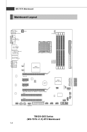
MS-7576 Mainboard Mainboard Layout Top : SPDIF Botto m: Keyboard or Mouse PWR1 Top: VGA port Bottom:DVI port Top: USB ports Bottom:HDMI T:1394 port (optional) M:USB ports B:eSATA port Top:LAN Jack Bottom: USB ports T:L ine- O ut M: C S -O ut B:SS-Out CPUFAN1 JPW R1 IDE1 SYSFAN1 SYSFAN2 S Y S FA N 3 S ATA 2_3 S ATA4_ 5 JTPM1 JFP1 JFP2 JAUD1 JCD1 JSP1 J1394_1 (opt i on al) BATT + JSPI1 SATA1 FDD1 JUSB1 JUSB2 JUSB3 JCOM1 790GX-G65 Series (MS-7576 v1.X) ATX Mainboard 1-4 In M: Li ne-O ut B:Mic T:R S -
MS-7576 Mainboard Mainboard Layout Top : SPDIF Botto m: Keyboard or Mouse PWR1 Top: VGA port Bottom:DVI port Top: USB ports Bottom:HDMI T:1394 port (optional) M:USB ports B:eSATA port Top:LAN Jack Bottom: USB ports T:L ine- O ut M: C S -O ut B:SS-Out CPUFAN1 JPW R1 IDE1 SYSFAN1 SYSFAN2 S Y S FA N 3 S ATA 2_3 S ATA4_ 5 JTPM1 JFP1 JFP2 JAUD1 JCD1 JSP1 J1394_1 (opt i on al) BATT + JSPI1 SATA1 FDD1 JUSB1 JUSB2 JUSB3 JCOM1 790GX-G65 Series (MS-7576 v1.X) ATX Mainboard 1-4 In M: Li ne-O ut B:Mic T:R S -

User Guide
Page 17
... to install the cooler to operate beyond product specifications. 2-3 Replaceing the CPU While replacing the CPU, always turn off the ATX power supply or unplug the power supply's power cord from overheating. For the latest information about CPU, please visit http://global.msi.com.tw/index. php?func=cpuform2 Important Overheating Overheating will seriously damage...
... to install the cooler to operate beyond product specifications. 2-3 Replaceing the CPU While replacing the CPU, always turn off the ATX power supply or unplug the power supply's power cord from overheating. For the latest information about CPU, please visit http://global.msi.com.tw/index. php?func=cpuform2 Important Overheating Overheating will seriously damage...

User Guide
Page 22
... of 450 watts (and above) is highly recommended for system stability. 2-8 You may use the 20-pin ATX power supply, please plug your power supply along with pin 1 & pin 13 (refer to the CPU. There is used to provide power to the image at the right hand). Make sure that all the... connectors are aligned. PWR1 3 4 1 2 Pin Definition PIN SIGNAL 1 GND 2 GND 3 12V 4 12V pin 13 pin 12 Important 1. To connect the ATX 24-pin power supply, make sure...
... of 450 watts (and above) is highly recommended for system stability. 2-8 You may use the 20-pin ATX power supply, please plug your power supply along with pin 1 & pin 13 (refer to the CPU. There is used to provide power to the image at the right hand). Make sure that all the... connectors are aligned. PWR1 3 4 1 2 Pin Definition PIN SIGNAL 1 GND 2 GND 3 12V 4 12V pin 13 pin 12 Important 1. To connect the ATX 24-pin power supply, make sure...


