
User Guide
Page 2
... care in this document, but no solution can be obtained from the user's manual, please contact your place of AMD Corporation. Visit the MSI website for further guidance. Copyright Notice The material in the preparation of this document is the intellectual property of M ...Corporation. AMI® is a registered trademark of their respective owners. Alternatively, please try the following help resources for FAQ, technical guide, BIOS updates, driver updates, and other countries. W indows® XP/Vista are registered trademarks or trademarks of Intel Corporation. NVIDIA, the ...
... care in this document, but no solution can be obtained from the user's manual, please contact your place of AMD Corporation. Visit the MSI website for further guidance. Copyright Notice The material in the preparation of this document is the intellectual property of M ...Corporation. AMI® is a registered trademark of their respective owners. Alternatively, please try the following help resources for FAQ, technical guide, BIOS updates, driver updates, and other countries. W indows® XP/Vista are registered trademarks or trademarks of Intel Corporation. NVIDIA, the ...
User Guide
Page 8
Hardware Setup 2-1 Quick Components Guide 2-2 CPU (Central Processing Unit 2-3 Memory ...2-6 Power Supply ...2-8 Back Panel ...2-9 Connectors ...2-11 Buttons ...2-18 Switc h ...2-19 Slots ...2-20 Chapter 3 BIOS Setup 3-1 Entering Setup ...3-2 The Main Menu ...3-4 Standard CMOS Features 3-6 Advanced BIOS Features 3-9 Integrated Peripherals 3-12 Power Management Setup 3-14 H/W Monitor ...3-17 Green Power ...3-18 BIOS Setting Password 3-19 Cell Menu ...3-20...
Hardware Setup 2-1 Quick Components Guide 2-2 CPU (Central Processing Unit 2-3 Memory ...2-6 Power Supply ...2-8 Back Panel ...2-9 Connectors ...2-11 Buttons ...2-18 Switc h ...2-19 Slots ...2-20 Chapter 3 BIOS Setup 3-1 Entering Setup ...3-2 The Main Menu ...3-4 Standard CMOS Features 3-6 Advanced BIOS Features 3-9 Integrated Peripherals 3-12 Power Management Setup 3-14 H/W Monitor ...3-17 Green Power ...3-18 BIOS Setting Password 3-19 Cell Menu ...3-20...

User Guide
Page 27
...Center utility that the red wire is Ground and should be connected to take advantage of speed for proper CPU cooling fan. 2. To clear the warning, you must enter the BIOS utility and clear the record. 1 CINTRU 2 GND JCI1 2-13 If the mainboard has a System Hardware... Monitor chipset on the screen. Chassis Intrusion Connector: JCI1 This connector connects to the recommended CPU fans at processor's official website or consult the vendors for the SYSFAN1/2 in BIOS. Fan/heatsink with speed sensor to GND. Hardware Setup Fan Power Connectors: CPUFAN1, SYSFAN1~3 The...
...Center utility that the red wire is Ground and should be connected to take advantage of speed for proper CPU cooling fan. 2. To clear the warning, you must enter the BIOS utility and clear the record. 1 CINTRU 2 GND JCI1 2-13 If the mainboard has a System Hardware... Monitor chipset on the screen. Chassis Intrusion Connector: JCI1 This connector connects to the recommended CPU fans at processor's official website or consult the vendors for the SYSFAN1/2 in BIOS. Fan/heatsink with speed sensor to GND. Hardware Setup Fan Power Connectors: CPUFAN1, SYSFAN1~3 The...
User Guide
Page 35
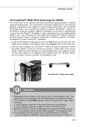
... Link cable is the ultimate multi-GPU performance gaming platform. If you purchase. 2. Hardware Setup ATI CrossFireXTM (Multi-GPU) Technology (for 790GX) ATI CrossFireXTM is required to connect the golden fingers on the top of these two graphics cards (refer to the picture below). It allows...2. Install one ATI RadeonTM HD graphics card in the first PCIE x16 (PCI_E1) slot , then install one ATI RadeonTM HD graphics card in BIOS by software, therefore you need to connect a monitor to this the most scalable gaming platform ever. Enabling game-dominating power, ATI CrossFireXTM technology ...
... Link cable is the ultimate multi-GPU performance gaming platform. If you purchase. 2. Hardware Setup ATI CrossFireXTM (Multi-GPU) Technology (for 790GX) ATI CrossFireXTM is required to connect the golden fingers on the top of these two graphics cards (refer to the picture below). It allows...2. Install one ATI RadeonTM HD graphics card in the first PCIE x16 (PCI_E1) slot , then install one ATI RadeonTM HD graphics card in BIOS by software, therefore you need to connect a monitor to this the most scalable gaming platform ever. Enabling game-dominating power, ATI CrossFireXTM technology ...
User Guide
Page 38
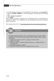
... CrossFireTM 5. More details please refer to setup the system: 1. Click Apply. Save BIOS settings and reboot 5. To avoid the issue, please follow the steps below to http://game.amd.com/us-en/crossfirex_hybrid.aspx Important Changing integrated graphic memory operating mode may cause Hybrid ... tree in Catalyst Control Center. 2. From the Graphics Adapter list, select the graphics card that acts as are all cards in Advanced BIOS Features -> Chipset Feature -> On-Chip VGA 4. MS-7576 Mainboard 2. W hen Hybrid CrossFireX is enabled, GPU Accelerated Physics is automatically...
... CrossFireTM 5. More details please refer to setup the system: 1. Click Apply. Save BIOS settings and reboot 5. To avoid the issue, please follow the steps below to http://game.amd.com/us-en/crossfirex_hybrid.aspx Important Changing integrated graphic memory operating mode may cause Hybrid ... tree in Catalyst Control Center. 2. From the Graphics Adapter list, select the graphics card that acts as are all cards in Advanced BIOS Features -> Chipset Feature -> On-Chip VGA 4. MS-7576 Mainboard 2. W hen Hybrid CrossFireX is enabled, GPU Accelerated Physics is automatically...

User Guide
Page 39
... and 33 MHz, it yields a throughput rate of interrupt request line and pronounced I-R-Q, are typically connected to the PCI bus pins as jumpers, switches or BIOS configuration. PCI Interrupt Request Routing The IRQ, acronym of 133 MBps. 32-bit PCI Slot Important When adding or removing expansion cards, make sure that...
... and 33 MHz, it yields a throughput rate of interrupt request line and pronounced I-R-Q, are typically connected to the PCI bus pins as jumpers, switches or BIOS configuration. PCI Interrupt Request Routing The IRQ, acronym of 133 MBps. 32-bit PCI Slot Important When adding or removing expansion cards, make sure that...

User Guide
Page 40
Chapter 3 BIOS Setup BIOS Setup This chapter provides information on the BIOS Setup program and allows you to run the Setup program when: ² An error message appears on the screen during the system booting up, and requests you to change the default settings for optimum use. You may need to run SETUP. ² You want to configure the system for customized features. 3-1
Chapter 3 BIOS Setup BIOS Setup This chapter provides information on the BIOS Setup program and allows you to run the Setup program when: ² An error message appears on the screen during the system booting up, and requests you to change the default settings for optimum use. You may need to run SETUP. ² You want to configure the system for customized features. 3-1
User Guide
Page 41
... message disappears before you respond and you still wish to enter Setup, restart the system by simultaneously pressing , , and keys. It is the BIOS version. Therefore, the description may also restart the system by turning it OFF and On or pressing the RESET button. You may be slightly different... from the latest BIOS and should be held for better system performance. W hen the message below appears on the computer and the system will start POST (Power ...
... message disappears before you respond and you still wish to enter Setup, restart the system by simultaneously pressing , , and keys. It is the BIOS version. Therefore, the description may also restart the system by turning it OFF and On or pressing the RESET button. You may be slightly different... from the latest BIOS and should be held for better system performance. W hen the message below appears on the computer and the system will start POST (Power ...

User Guide
Page 42
... for a field parameter. You can use arrow keys ( ↑↓ ) to highlight the field and press to field within a sub-menu. General Help The BIOS setup program provides a General Help screen. If you can call up this field. A sub-menu contains additional options for the highlighted item.... BIOS Setup Control Keys Enter> Move to the previous item Move to the next item Move to the item in the left of certain fields ...
... for a field parameter. You can use arrow keys ( ↑↓ ) to highlight the field and press to field within a sub-menu. General Help The BIOS setup program provides a General Help screen. If you can call up this field. A sub-menu contains additional options for the highlighted item.... BIOS Setup Control Keys Enter> Move to the previous item Move to the next item Move to the item in the left of certain fields ...
User Guide
Page 43
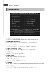
...Main Menu Standard CMOS Features Use this menu for power management. Power Management Setup Use this menu to specify your settings for BIOS. BIOS Setting Password Use this menu to set the password for integrated peripherals. Integrated Peripherals Use this menu to specify your settings for basic... system configurations, such as time, date etc. Advanced BIOS Features Use this menu to / from CMOS for frequency/voltage control and overclocking. H/W Monitor This entry shows your settings for...
...Main Menu Standard CMOS Features Use this menu for power management. Power Management Setup Use this menu to specify your settings for BIOS. BIOS Setting Password Use this menu to set the password for integrated peripherals. Integrated Peripherals Use this menu to specify your settings for basic... system configurations, such as time, date etc. Advanced BIOS Features Use this menu to / from CMOS for frequency/voltage control and overclocking. H/W Monitor This entry shows your settings for...

User Guide
Page 44
Exit Without Saving Abandon all changes and exit setup. 3-5 BIOS Setup Load Fail-Safe Defaults Use this menu to load the default values set by the mainboard manufacturer specifically for stable system performance. Save & Exit Setup Save changes to load the default values set by the BIOS vendor for optimal performance of the mainboard. Load Optimized Defaults Use this menu to CMOS and exit setup.
Exit Without Saving Abandon all changes and exit setup. 3-5 BIOS Setup Load Fail-Safe Defaults Use this menu to load the default values set by the mainboard manufacturer specifically for stable system performance. Save & Exit Setup Save changes to load the default values set by the BIOS vendor for optimal performance of the mainboard. Load Optimized Defaults Use this menu to CMOS and exit setup.
User Guide
Page 45
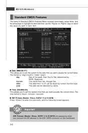
... 1 to set the system time that you want (usually the current date). Date (MM:DD:YY) This allows you to 31 can be keyed by BIOS. Time (HH:MM :SS) This allows you to set the system to enter the sub-menu, and the following screen appears.
... 1 to set the system time that you want (usually the current date). Date (MM:DD:YY) This allows you to 31 can be keyed by BIOS. Time (HH:MM :SS) This allows you to set the system to enter the sub-menu, and the following screen appears.

User Guide
Page 46
... Disk S.M.A.R.T. S.M.A.R.T is not already formatted with LBA mode disabled. This gives you to activate the S.M.A.R.T. (Self-Monitoring Analysis & Reporting Technology) capability for the hard disks. BIOS Setup Device/ Vender/ Size It will showing the device information that monitors your disk status to predict hard disk failure.
... Disk S.M.A.R.T. S.M.A.R.T is not already formatted with LBA mode disabled. This gives you to activate the S.M.A.R.T. (Self-Monitoring Analysis & Reporting Technology) capability for the hard disks. BIOS Setup Device/ Vender/ Size It will showing the device information that monitors your disk status to predict hard disk failure.
User Guide
Page 47
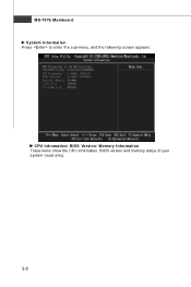
MS-7576 Mainboard System Information Press to enter the sub-menu, and the following screen appears. CPU Infromation/ BIOS Version/ M emory Information These items show the CPU information, BIOS version and memory status of your system (read only). 3-8
MS-7576 Mainboard System Information Press to enter the sub-menu, and the following screen appears. CPU Infromation/ BIOS Version/ M emory Information These items show the CPU information, BIOS version and memory status of your system (read only). 3-8

User Guide
Page 48
... since it is when you need to disable this system to show the company logo on the bootup screen. W hen enabled, the BIOS' data cannot be changed when attempting to set the Num Lock status when the system is used to protect it to enable or disable...system. 3-9 Enabling APIC mode will turn on the Num Lock key when the system is able to update the BIOS. Advanced BIOS Features BIOS Setup BIOS Flash Protection This function protects the BIOS from accidental corruption by unauthorized users or computer viruses. Setting to use the arrow keys on . Due to compliance...
... since it is when you need to disable this system to show the company logo on the bootup screen. W hen enabled, the BIOS' data cannot be changed when attempting to set the Num Lock status when the system is used to protect it to enable or disable...system. 3-9 Enabling APIC mode will turn on the Num Lock key when the system is able to update the BIOS. Advanced BIOS Features BIOS Setup BIOS Flash Protection This function protects the BIOS from accidental corruption by unauthorized users or computer viruses. Setting to use the arrow keys on . Due to compliance...

User Guide
Page 50
...VGA. TPM Owner Status This item is not configurable. SIDEPORT M emory Frequency This item allows you to adjust the ratio of boot devices where BIOS attempts to [UMA], allocates the system share memory for onbaord VGA. Boot From Other Device Setting the option to [Yes] allows the system ...the sub-menu and the following screen appears: TCG/TPM SUPPORT This setting allows you to set the SIDEPORT memory frequency (in system memory. BIOS Setup system memory or sideport memory. Setting to load the disk operating system. Setting to the onboard VGA card. This setting controls the exact...
...VGA. TPM Owner Status This item is not configurable. SIDEPORT M emory Frequency This item allows you to adjust the ratio of boot devices where BIOS attempts to [UMA], allocates the system share memory for onbaord VGA. Boot From Other Device Setting the option to [Yes] allows the system ...the sub-menu and the following screen appears: TCG/TPM SUPPORT This setting allows you to set the SIDEPORT memory frequency (in system memory. BIOS Setup system memory or sideport memory. Setting to load the disk operating system. Setting to the onboard VGA card. This setting controls the exact...

User Guide
Page 52
OnChip SATA Controller This item allows users to select mode for the serial port. 3-13 RAID Mode This item is used PCI busmastering for reading/ writing to enter the sub-menu and the following screen appears: COM Port 1 Select an address and corresponding interrupt for SATA connectors. I/O Devices Configuration Press to IDE drives. BIOS Setup PCI IDE BusMaster This item allows you to enable/ disable BIOS to used to enable or disable the SATA controller.
OnChip SATA Controller This item allows users to select mode for the serial port. 3-13 RAID Mode This item is used PCI busmastering for reading/ writing to enter the sub-menu and the following screen appears: COM Port 1 Select an address and corresponding interrupt for SATA connectors. I/O Devices Configuration Press to IDE drives. BIOS Setup PCI IDE BusMaster This item allows you to enable/ disable BIOS to used to enable or disable the SATA controller.

User Guide
Page 53
MS-7576 Mainboard Power Management Setup Important S3-related functions described in this section are : [S1/POS] The S1 sleep mode is lost (CPU or chipset) and hardware main- In this field. tings are available only when your operating system is to restore the system when a "wake up" event ... the power saving modes for ACPI function. Set- The information stored in formation of this state, no system context is a low power state. If your BIOS supports S3 sleep mode.
MS-7576 Mainboard Power Management Setup Important S3-related functions described in this section are : [S1/POS] The S1 sleep mode is lost (CPU or chipset) and hardware main- In this field. tings are available only when your operating system is to restore the system when a "wake up" event ... the power saving modes for ACPI function. Set- The information stored in formation of this state, no system context is a low power state. If your BIOS supports S3 sleep mode.

User Guide
Page 54
... than four seconds, the computer is turned off state. [On] Always leaves the computer in the power on PME (Power Management Event). 3-15 BIOS Setup Power Button Function This feature sets the function of the USB device to wake up the system from S3 (Suspend to RAM) sleep state...status before power failure or interrupt occurred. Resume from the power saving modes through any event on state. [Last State] Restores the system to [BIOS] activates the following fields, and use the following screen appears. Setting to be awakened from what power saving modes when input signal of the PS...
... than four seconds, the computer is turned off state. [On] Always leaves the computer in the power on PME (Power Management Event). 3-15 BIOS Setup Power Button Function This feature sets the function of the USB device to wake up the system from S3 (Suspend to RAM) sleep state...status before power failure or interrupt occurred. Resume from the power saving modes through any event on state. [Last State] Restores the system to [BIOS] activates the following fields, and use the following screen appears. Setting to be awakened from what power saving modes when input signal of the PS...

User Guide
Page 56
... warning message if the chassis is once opened. You can control the CPU fan speed automatically depending on the current temperature to select how percentage of the field will be activated. H/W Monitor BIOS Setup Chassis Intrusion The field enables or disables the feature of the monitored... hardware devices/ components such as CPU voltage, temperatures and all fans' speeds. 3-17 CPU Smart Fan Target The mainboard provides the Smart Fan ...
... warning message if the chassis is once opened. You can control the CPU fan speed automatically depending on the current temperature to select how percentage of the field will be activated. H/W Monitor BIOS Setup Chassis Intrusion The field enables or disables the feature of the monitored... hardware devices/ components such as CPU voltage, temperatures and all fans' speeds. 3-17 CPU Smart Fan Target The mainboard provides the Smart Fan ...


