
User Guide
Page 2
... intellectual property of M ICRO-STAR INTERNATIONAL. func=service Contact our technical staff at: http://ocss.msi.com.tw ii Trademarks All trademarks are registered trademarks of AMD Corporation. AMD, Athlon™, Athlon™ XP, Thoroughbred™, and Duron™ are the properties of ...their respective owners. Visit the MSI website for further guidance. We take every care in the preparation...
... intellectual property of M ICRO-STAR INTERNATIONAL. func=service Contact our technical staff at: http://ocss.msi.com.tw ii Trademarks All trademarks are registered trademarks of AMD Corporation. AMD, Athlon™, Athlon™ XP, Thoroughbred™, and Duron™ are the properties of ...their respective owners. Visit the MSI website for further guidance. We take every care in the preparation...

User Guide
Page 3
Keep this equipment away from overheating. Place the power cord such a way that could damage or cause electrical s h oc k . 11. CAUT ION: Danger of the following situations arises, get it work according to the power inlet. 7. Always read the safety instructions carefully. 2. Keep this equipment on a reliable flat surface before inserting any add-on card or module. 9. The openings on if bat ter y i s i nc orrec tl y r epl ac ed. Do not place anything over the power cord. 8. DO NOT LEAVETHIS EQUIPMENT INANENVIRONMENT UNCONDITIONED, STORAGE TEMPERATURE ABOVE 600 C (1400F), IT ...
Keep this equipment away from overheating. Place the power cord such a way that could damage or cause electrical s h oc k . 11. CAUT ION: Danger of the following situations arises, get it work according to the power inlet. 7. Always read the safety instructions carefully. 2. Keep this equipment on a reliable flat surface before inserting any add-on card or module. 9. The openings on if bat ter y i s i nc orrec tl y r epl ac ed. Do not place anything over the power cord. 8. DO NOT LEAVETHIS EQUIPMENT INANENVIRONMENT UNCONDITIONED, STORAGE TEMPERATURE ABOVE 600 C (1400F), IT ...
User Guide
Page 4
If this device must accept any , must be determined by turning the equipment off and on a circuit different from that to which the receiver is subject to the following two conditions: (1) this device may not cause harmful interference, and (2) this equipment does cause harmful interference to radio or television reception, which can radiate radio frequency energy and, if not installed and used in order to comply with the instructions, may cause undesired operation. Operation is connected. † Consult the dealer or an experienced radio/television technician for help. power ...
If this device must accept any , must be determined by turning the equipment off and on a circuit different from that to which the receiver is subject to the following two conditions: (1) this device may not cause harmful interference, and (2) this equipment does cause harmful interference to radio or television reception, which can radiate radio frequency energy and, if not installed and used in order to comply with the instructions, may cause undesired operation. Operation is connected. † Consult the dealer or an experienced radio/television technician for help. power ...

User Guide
Page 5
WEEE (Waste Electrical and Electronic Equipment) Statement v
WEEE (Waste Electrical and Electronic Equipment) Statement v
User Guide
Page 8
Hardware Setup 2-1 Quick Components Guide 2-2 CPU (Central Processing Unit 2-3 Memory ...2-6 Power Supply ...2-8 Back Panel ...2-9 Connectors ...2-11 Buttons ...2-18 Switc h ...2-19 Slots ...2-20 Chapter 3 BIOS Setup 3-1 Entering Setup ...3-2 The Main Menu ...3-4 Standard ...
Hardware Setup 2-1 Quick Components Guide 2-2 CPU (Central Processing Unit 2-3 Memory ...2-6 Power Supply ...2-8 Back Panel ...2-9 Connectors ...2-11 Buttons ...2-18 Switc h ...2-19 Slots ...2-20 Chapter 3 BIOS Setup 3-1 Entering Setup ...3-2 The Main Menu ...3-4 Standard ...

User Guide
Page 9
Appendix B Overclocking Center B-1 Activating Overclocking Center B-2 System Info ...B-3 DOT ...B-5 Appendix C SATA RAID C-1 RAID Configuration C-2 ix
Appendix B Overclocking Center B-1 Activating Overclocking Center B-2 System Info ...B-3 DOT ...B-5 Appendix C SATA RAID C-1 RAID Configuration C-2 ix

User Guide
Page 10
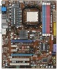
Designed to fit the advanced 64bit AMD Phenom II processor, the 790GX-G65 Series deliver a high performance and professional desktop platform solution. 1-1 Getting Started Chapter 1 Getting Started Thank you for optimal system efficiency. The 790GX-G65 Series mainboards are based on AMD 790GX/780G & SB710/ SB750 chipset for choosing the 790GX-G65 Series (MS7576 v1.X) ATX mainboard.
Designed to fit the advanced 64bit AMD Phenom II processor, the 790GX-G65 Series deliver a high performance and professional desktop platform solution. 1-1 Getting Started Chapter 1 Getting Started Thank you for optimal system efficiency. The 790GX-G65 Series mainboards are based on AMD 790GX/780G & SB710/ SB750 chipset for choosing the 790GX-G65 Series (MS7576 v1.X) ATX mainboard.
User Guide
Page 11
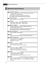
...240pin/1.5V) (For more information on compatible components, please visit ht t p: / / global. Supports AMD® PhenomTM II X4/ X3 and Athlon X4 /X3/ X2 processors in the AM3 package. (For the latest information about CPU, please visit ht t p : / / global. m si. t w / index. Supports storage... and data transfers at up to 5.2GT/s Chipset - t w / ind ex. North Bridge: AMD® 790GX / 780G chipset - Supports Ultra DMA 66/100/133 mode ...
...240pin/1.5V) (For more information on compatible components, please visit ht t p: / / global. Supports AMD® PhenomTM II X4/ X3 and Athlon X4 /X3/ X2 processors in the AM3 package. (For the latest information about CPU, please visit ht t p : / / global. m si. t w / index. Supports storage... and data transfers at up to 5.2GT/s Chipset - t w / ind ex. North Bridge: AMD® 790GX / 780G chipset - Supports Ultra DMA 66/100/133 mode ...

User Guide
Page 12
... Audio pinheader - 1 Chassis Intrusion Switch pinheader - 1 Serial port connector - 1 TPM pinheader (optional) - 1 OC switch - 1 Power LED Button - 1 Reset LED Button - 1 Clear CMOS Button Slots For 790GX - 1 PCI Express x16 slot supports up to PCI Express x16 speed. When dual graphic cards enabled, it will turn to x8 speed. - 1 PCI Express x16...
... Audio pinheader - 1 Chassis Intrusion Switch pinheader - 1 Serial port connector - 1 TPM pinheader (optional) - 1 OC switch - 1 Power LED Button - 1 Reset LED Button - 1 Clear CMOS Button Slots For 790GX - 1 PCI Express x16 slot supports up to PCI Express x16 speed. When dual graphic cards enabled, it will turn to x8 speed. - 1 PCI Express x16...
User Guide
Page 13
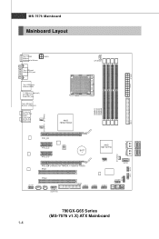
O ut M: C S -O ut B:SS-Out CPUFAN1 JPW R1 IDE1 SYSFAN1 SYSFAN2 S Y S FA N 3 S ATA 2_3 S ATA4_ 5 JTPM1 JFP1 JFP2 JAUD1 JCD1 JSP1 J1394_1 (opt i on al) BATT + JSPI1 SATA1 FDD1 JUSB1 JUSB2 JUSB3 JCOM1 790GX-G65 Series (MS-7576 v1.X) ATX Mainboard 1-4 In M: Li ne-O ut B:Mic T:R S - MS-7576 Mainboard Mainboard Layout Top : SPDIF Botto m: Keyboard or Mouse PWR1 Top: VGA port Bottom:DVI port Top: USB ports Bottom:HDMI T:1394 port (optional) M:USB ports B:eSATA port Top:LAN Jack Bottom: USB ports T:L ine-
O ut M: C S -O ut B:SS-Out CPUFAN1 JPW R1 IDE1 SYSFAN1 SYSFAN2 S Y S FA N 3 S ATA 2_3 S ATA4_ 5 JTPM1 JFP1 JFP2 JAUD1 JCD1 JSP1 J1394_1 (opt i on al) BATT + JSPI1 SATA1 FDD1 JUSB1 JUSB2 JUSB3 JCOM1 790GX-G65 Series (MS-7576 v1.X) ATX Mainboard 1-4 In M: Li ne-O ut B:Mic T:R S - MS-7576 Mainboard Mainboard Layout Top : SPDIF Botto m: Keyboard or Mouse PWR1 Top: VGA port Bottom:DVI port Top: USB ports Bottom:HDMI T:1394 port (optional) M:USB ports B:eSATA port Top:LAN Jack Bottom: USB ports T:L ine-

User Guide
Page 14
Packing Checklist Getting Started MSI motherboard MSI Driver/Utility DVD SATA Cable Power Cable Standard Cable for IDE Devices Back IO Shield User's Guide * The pictures are for reference only and may vary from the packing contents of the product you purchased. 1-5
Packing Checklist Getting Started MSI motherboard MSI Driver/Utility DVD SATA Cable Power Cable Standard Cable for IDE Devices Back IO Shield User's Guide * The pictures are for reference only and may vary from the packing contents of the product you purchased. 1-5

User Guide
Page 15
Hardware Setup Chapter 2 Hardware Setup This chapter provides you install in holding the components and follow the installation procedures. Use a grounded wrist strap before handling computer components. While doing the installation, be careful in the wrong orientation, the components will not work properly. Static electricity may damage the components. 2-1 For some components, if you with the information about hardware setup procedures.
Hardware Setup Chapter 2 Hardware Setup This chapter provides you install in holding the components and follow the installation procedures. Use a grounded wrist strap before handling computer components. While doing the installation, be careful in the wrong orientation, the components will not work properly. Static electricity may damage the components. 2-1 For some components, if you with the information about hardware setup procedures.

User Guide
Page 17
... is designed to support overclocking. We do not have the CPU cooler, consult your components are installing the CPU, make sure to install the cooler to prevent overheating. For the latest information about CPU, please visit http://global.msi.com.tw/index. If you apply an even layer of... CPU. Any attempt to operate beyond product specifications. 2-3 Replaceing the CPU While replacing the CPU, always turn off the ATX power supply or unplug ...
... is designed to support overclocking. We do not have the CPU cooler, consult your components are installing the CPU, make sure to install the cooler to prevent overheating. For the latest information about CPU, please visit http://global.msi.com.tw/index. If you apply an even layer of... CPU. Any attempt to operate beyond product specifications. 2-3 Replaceing the CPU While replacing the CPU, always turn off the ATX power supply or unplug ...

User Guide
Page 18
... your mainboard. 4. Meanwhile, do not forget to a 90-degree angle. 2. Pull the lever sideways away from the socket. Press the CPU down firmly into the socket and can only fit in the picture. W rong installation will cause the damage of the correct installation procedures may ... should be seen. T he gold arrow s hould point as shown in the correct orientation. 3. The CPU can not be completely embedded into the socket and close the lever with your CPU & mainboard. 1. As the CPU is likely to move while the lever is being closed, always close the lever. Follow the steps...
... your mainboard. 4. Meanwhile, do not forget to a 90-degree angle. 2. Pull the lever sideways away from the socket. Press the CPU down firmly into the socket and can only fit in the picture. W rong installation will cause the damage of the correct installation procedures may ... should be seen. T he gold arrow s hould point as shown in the correct orientation. 3. The CPU can not be completely embedded into the socket and close the lever with your CPU & mainboard. 1. As the CPU is likely to move while the lever is being closed, always close the lever. Follow the steps...

User Guide
Page 19
.... 6. Position the cooling set on your mainboard may vary depending on the mainboard. Hook one end of the retention mechanism. Attach the CPU Fan cable to keep an eye on the top of the clip to fasten the cooling set onto the retention mechanism. Mainboard photos shown ...for Socket AM2+ CPUs only. The appearance of the cooler installation for demonstration of your fingers, because once the Safety Hook is necessary to the CPU fan connector on the model you purchase. 2. While disconnecting the Safety Hook from the fixed bolt, the fixed lever will spring back instantly. ...
.... 6. Position the cooling set on your mainboard may vary depending on the mainboard. Hook one end of the retention mechanism. Attach the CPU Fan cable to keep an eye on the top of the clip to fasten the cooling set onto the retention mechanism. Mainboard photos shown ...for Socket AM2+ CPUs only. The appearance of the cooler installation for demonstration of your fingers, because once the Safety Hook is necessary to the CPU fan connector on the model you purchase. 2. While disconnecting the Safety Hook from the fixed bolt, the fixed lever will spring back instantly. ...
User Guide
Page 20
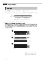
... two data bus lines simultaneously. Please refer to the following illustrations for installing memory modules. For more information on compatible components, please visit http://global.msi.com. tw/index.php?func=testreport DDR3 240-pin, 1.5V 48x2=96 pin 72x2=144 pin Dual-Channel: Channel A in PINK Dual-Channel Memory Population...
... two data bus lines simultaneously. Please refer to the following illustrations for installing memory modules. For more information on compatible components, please visit http://global.msi.com. tw/index.php?func=testreport DDR3 240-pin, 1.5V 48x2=96 pin 72x2=144 pin Dual-Channel: Channel A in PINK Dual-Channel Memory Population...

User Guide
Page 21
The plastic clip at the sides. Important You can barely see the golden finger if the memory module is not backwards compatible. You should always install DDR3 memory modules in the DIMM slot. Manually check if the memory module has been locked in place by the DIMM slot clips at each side of the same type and density in different channel DDR DIMMs. - In dual-channel mode, make sure that you install memory modules of the DIMM slot will only fit in the DIMM slot. 3. To enable successful system boot-up, always insert the memory modules into the DIMM slot. Volt Notch ...
The plastic clip at the sides. Important You can barely see the golden finger if the memory module is not backwards compatible. You should always install DDR3 memory modules in the DIMM slot. Manually check if the memory module has been locked in place by the DIMM slot clips at each side of the same type and density in different channel DDR DIMMs. - In dual-channel mode, make sure that you install memory modules of the DIMM slot will only fit in the DIMM slot. 3. To enable successful system boot-up, always insert the memory modules into the DIMM slot. Volt Notch ...

User Guide
Page 22
... also a foolproof design on pin 11, 12, 23 & 24 to ensure stable operation of 450 watts (and above) is used to provide power to the CPU. Make sure that all the connectors are aligned. There is inserted in the proper orientation and the pins are connected to proper ATX power supplies...
... also a foolproof design on pin 11, 12, 23 & 24 to ensure stable operation of 450 watts (and above) is used to provide power to the CPU. Make sure that all the connectors are aligned. There is inserted in the proper orientation and the pins are connected to proper ATX power supplies...

User Guide
Page 23
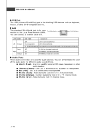
Important eSATA port only supports RAID and AHCI mode (does not support IDE mode) 2-9 To connect an LCD monitor, simply plug your monitor cable into the DVI-D connector, and make sure that the other end of transmitting uncompressed streams. HDMI supports all -digital audio/video interface capable of the cable is properly connected to your monitor manual for more information.) HDMI Port The High-Definition Multimedia Interface (HDMI) is for attaching the eSATA external hard drive. eSATA Port The eSATA port is an all TV format, including standard, enhanced, or high-definition video, ...
Important eSATA port only supports RAID and AHCI mode (does not support IDE mode) 2-9 To connect an LCD monitor, simply plug your monitor cable into the DVI-D connector, and make sure that the other end of transmitting uncompressed streams. HDMI supports all -digital audio/video interface capable of the cable is properly connected to your monitor manual for more information.) HDMI Port The High-Definition Multimedia Interface (HDMI) is for attaching the eSATA external hard drive. eSATA Port The eSATA port is an all TV format, including standard, enhanced, or high-definition video, ...
User Guide
Page 24
Link Indicator LED Color Left Orange Green Right Orange LED State Condition Off LAN link is selected. On 100 Mbit/sec data rate is not established. You can connect a network cable to the Local Area Network (LAN). Line-Out (Green) - Mic, is a connector for speakers or headphones. SS-Out (Gray) - Side-Surround Out 7.1 channel mode. 2-10 You can differentiate the color of the audio jacks for different audio sound effects. Line Out, is a connector for microphones. Center/ Subwoofer Out in 4/ 5.1/ 7.1 channel mode. Off 10 Mbit/sec data rate is used for audio devices....
Link Indicator LED Color Left Orange Green Right Orange LED State Condition Off LAN link is selected. On 100 Mbit/sec data rate is not established. You can connect a network cable to the Local Area Network (LAN). Line-Out (Green) - Mic, is a connector for speakers or headphones. SS-Out (Gray) - Side-Surround Out 7.1 channel mode. 2-10 You can differentiate the color of the audio jacks for different audio sound effects. Line Out, is a connector for microphones. Center/ Subwoofer Out in 4/ 5.1/ 7.1 channel mode. Off 10 Mbit/sec data rate is used for audio devices....
