User Manual
Page 1
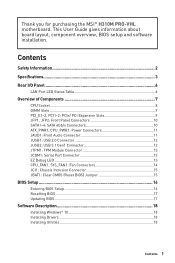
...: Power Connectors 11 JAUD1: Front Audio Connector 11 JUSB1: USB 2.0 Connector 12 JUSB2: USB 3.1 Gen1 Connector 12 JTPM1: TPM Module Connector 13 JCOM1: Serial Port Connector 13 EZ Debug LED 13 CPU_FAN1, SYS_FAN1: Fan Connectors 14 JCI1: Chassis Intrusion Connector 15 JBAT1: Clear CMOS (Reset BIOS) Jumper 15 BIOS Setup ...16 Entering BIOS Setup 16 Resetting BIOS 17 Updating BIOS 17 Software Description 18 Installing Windows® 10 18 Installing Drivers 18 Installing Utilities 18 Contents 1 This User Guide gives information about board layout, component overview, BIOS setup...
...: Power Connectors 11 JAUD1: Front Audio Connector 11 JUSB1: USB 2.0 Connector 12 JUSB2: USB 3.1 Gen1 Connector 12 JTPM1: TPM Module Connector 13 JCOM1: Serial Port Connector 13 EZ Debug LED 13 CPU_FAN1, SYS_FAN1: Fan Connectors 14 JCI1: Chassis Intrusion Connector 15 JBAT1: Clear CMOS (Reset BIOS) Jumper 15 BIOS Setup ...16 Entering BIOS Setup 16 Resetting BIOS 17 Updating BIOS 17 Software Description 18 Installing Windows® 10 18 Installing Drivers 18 Installing Utilities 18 Contents 1 This User Guide gives information about board layout, component overview, BIOS setup...

User Manual
Page 2
.... y Always turn off the power supply and unplug the power cord from the power outlet before connecting the PSU to user guide. ƒ The motherboard has been dropped and damaged. ƒ The motherboard has obvious sign of breakage. y Place the power cord such a way that all components are no loose screws or metal components on the PSU, before installing or removing any installation step...
.... y Always turn off the power supply and unplug the power cord from the power outlet before connecting the PSU to user guide. ƒ The motherboard has been dropped and damaged. ƒ The motherboard has obvious sign of breakage. y Place the power cord such a way that all components are no loose screws or metal components on the PSU, before installing or removing any installation step...
User Manual
Page 3
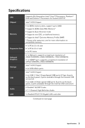
...@60Hz, 1920x1200@60Hz y 1x HDMI™ port, supports a maximum resolution of 4096x2160@30Hz, 2560x1600@60Hz Storage USB Intel® H310 Chipset y 4x SATA 6Gb/s ports Intel® H310 Chipset y 4x USB 3.1 Gen1 (SuperSpeed USB) ports (2 Type-A ports on the back panel, 2 ports available through the internal USB connector) y 6x USB 2.0 (High-speed USB) ports (4 ports on the back panel, 2 ports available through the internal USB connector) Audio y Realtek® ALC887 Codec y 7.1-Channel High Definition Audio LAN 1x Realtek RTL8111H Gigabit LAN controller Continued on compatible memory.
...@60Hz, 1920x1200@60Hz y 1x HDMI™ port, supports a maximum resolution of 4096x2160@30Hz, 2560x1600@60Hz Storage USB Intel® H310 Chipset y 4x SATA 6Gb/s ports Intel® H310 Chipset y 4x USB 3.1 Gen1 (SuperSpeed USB) ports (2 Type-A ports on the back panel, 2 ports available through the internal USB connector) y 6x USB 2.0 (High-speed USB) ports (4 ports on the back panel, 2 ports available through the internal USB connector) Audio y Realtek® ALC887 Codec y 7.1-Channel High Definition Audio LAN 1x Realtek RTL8111H Gigabit LAN controller Continued on compatible memory.
User Manual
Page 4
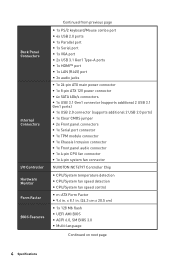
... in . Back Panel Connectors Internal Connectors I/O Controller Hardware Monitor Form Factor BIOS Features Continued from previous page y 1x PS/2 keyboard/Mouse combo port y 4x USB 2.0 ports y 1x Parallel port y 1x Serial port y 1x VGA port y 2x USB 3.1 Gen1 Type-A ports y 1x HDMI™ port y 1x LAN (RJ45) port y 3x audio jacks y 1x 24-pin ATX main power connector y 1x 8-pin ATX 12V power connector y 4x SATA 6Gb/s connectors y 1x USB 3.1 Gen1 connector (supports additional 2 USB 3.1 Gen1 ports) y 1x USB 2.0 connector (supports additional 2 USB 2.0 ports) y 1x Clear CMOS jumper y 2x Front...
... in . Back Panel Connectors Internal Connectors I/O Controller Hardware Monitor Form Factor BIOS Features Continued from previous page y 1x PS/2 keyboard/Mouse combo port y 4x USB 2.0 ports y 1x Parallel port y 1x Serial port y 1x VGA port y 2x USB 3.1 Gen1 Type-A ports y 1x HDMI™ port y 1x LAN (RJ45) port y 3x audio jacks y 1x 24-pin ATX main power connector y 1x 8-pin ATX 12V power connector y 4x SATA 6Gb/s connectors y 1x USB 3.1 Gen1 connector (supports additional 2 USB 3.1 Gen1 ports) y 1x USB 2.0 connector (supports additional 2 USB 2.0 ports) y 1x Clear CMOS jumper y 2x Front...
User Manual
Page 5
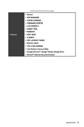
Software Continued from previous page y Drivers y APP MANAGER y SUPER CHARGER y COMMAND CENTER y LIVE UPDATE 6 y SMART TOOL y RAMDISK y FAST BOOT y X-BOOST y DPC LATENCY TUNER y MYSTIC LIGHT y CPU-Z MSI GAMING y Intel Extreme Tuning Utility y Google Chrome™ ,Google Toolbar, Google Drive y Norton™ Internet Security Solution Specifications 5
Software Continued from previous page y Drivers y APP MANAGER y SUPER CHARGER y COMMAND CENTER y LIVE UPDATE 6 y SMART TOOL y RAMDISK y FAST BOOT y X-BOOST y DPC LATENCY TUNER y MYSTIC LIGHT y CPU-Z MSI GAMING y Intel Extreme Tuning Utility y Google Chrome™ ,Google Toolbar, Google Drive y Norton™ Internet Security Solution Specifications 5

User Manual
Page 6
... Mbps connection Orange 1 Gbps connection Audio 7.1-channel Configuration To configure 7.1-channel audio, you which device is current connected. 6 Rear I/O Panel Plug your speakers to audio jacks on the Realtek HD Audio Manager > Advanced Settings to open the dialog below steps. 1. Rear I/O Panel USB 2.0 Parallel Port USB 3.1 Gen1 Line-in Line-out LAN Serial Port PS/2 Keyboard/ Mouse VGA Mic in . 3. Click on rear and front I /O module to connect front audio I /O panel. When you plug into a device at an audio jack, a dialogue window...
... Mbps connection Orange 1 Gbps connection Audio 7.1-channel Configuration To configure 7.1-channel audio, you which device is current connected. 6 Rear I/O Panel Plug your speakers to audio jacks on the Realtek HD Audio Manager > Advanced Settings to open the dialog below steps. 1. Rear I/O Panel USB 2.0 Parallel Port USB 3.1 Gen1 Line-in Line-out LAN Serial Port PS/2 Keyboard/ Mouse VGA Mic in . 3. Click on rear and front I /O module to connect front audio I /O panel. When you plug into a device at an audio jack, a dialogue window...

User Manual
Page 8
... the CPU socket pins by covering the socket with the CPU before installing or removing the CPU. y Confirm that the CPU heatsink has formed a tight seal with the plastic cap. Always make sure the cooling fans work properly to install a CPU heatsink. MSI will deal with Return Merchandise Authorization (RMA) requests if only the motherboard comes with the protective cap on the CPU socket. CPU Socket Please install the CPU into the CPU socket as...
... the CPU socket pins by covering the socket with the CPU before installing or removing the CPU. y Confirm that the CPU heatsink has formed a tight seal with the plastic cap. Always make sure the cooling fans work properly to install a CPU heatsink. MSI will deal with Return Merchandise Authorization (RMA) requests if only the motherboard comes with the protective cap on the CPU socket. CPU Socket Please install the CPU into the CPU socket as...
User Manual
Page 9
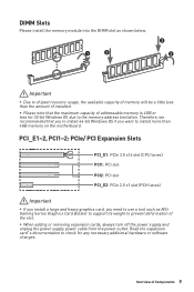
...-bit Windows OS if you need to use a tool such as shown below. 1 2 2 3 BAT1 Important y Due to chipset resource usage, the available capacity of memory will be a little less than 4GB memory on the motherboard. y When adding or removing expansion cards, always turn off the power supply and unplug the power supply power cable from the power outlet. DIMM Slots Please install the memory module into the DIMM slot as MSI Gaming Series Graphics Card...
...-bit Windows OS if you need to use a tool such as shown below. 1 2 2 3 BAT1 Important y Due to chipset resource usage, the available capacity of memory will be a little less than 4GB memory on the motherboard. y When adding or removing expansion cards, always turn off the power supply and unplug the power supply power cable from the power outlet. DIMM Slots Please install the memory module into the DIMM slot as MSI Gaming Series Graphics Card...

User Manual
Page 10
... front panel. 2 10 1 9 JFP1 1 HDD LED + 2 Power LED + 3 HDD LED - 4 Power LED - 5 Reset Switch 6 Power Switch 7 Reset Switch 8 Power Switch 9 Reserved 10 No Pin HDD LED RESET SW 1 JFP2 HDD LED HDD LED HDD LED + POWER LED POWER LED POWER LED + JFP1 1 Speaker - 2 Buzzer + 3 Buzzer - 4 Speaker + SATA1~4: SATA 6Gb/s Connectors These connectors are SATA 6Gb/s interface ports. JFP1, JFP2: Front Panel Connectors These connectors connect to the motherboard for space saving purposes. 10 Overview of the cable. Each connector can connect to one SATA device.
... front panel. 2 10 1 9 JFP1 1 HDD LED + 2 Power LED + 3 HDD LED - 4 Power LED - 5 Reset Switch 6 Power Switch 7 Reset Switch 8 Power Switch 9 Reserved 10 No Pin HDD LED RESET SW 1 JFP2 HDD LED HDD LED HDD LED + POWER LED POWER LED POWER LED + JFP1 1 Speaker - 2 Buzzer + 3 Buzzer - 4 Speaker + SATA1~4: SATA 6Gb/s Connectors These connectors are SATA 6Gb/s interface ports. JFP1, JFP2: Front Panel Connectors These connectors connect to the motherboard for space saving purposes. 10 Overview of the cable. Each connector can connect to one SATA device.

User Manual
Page 11
JAUD1: Front Audio Connector This connector allow you to ensure stable operation of Components 11 ATX_PWR1, CPU_PWR1: Power Connectors These connectors allow you to connect an ATX power supply. 1 +3.3V 13 2 +3.3V 14 12 24 3 Ground 15 4 +5V... +12V +12V Important Make sure that all the power cables are securely connected to a proper ATX power supply to connect audio jacks on the front panel. 1 MIC L 2 Ground 2 10 3 MIC R 4 NC 5 Head Phone R 6 1 9 7 SENSE_SEND 8 MIC Detection No Pin 9 Head Phone L 10 Head Phone Detection Overview of the motherboard.
JAUD1: Front Audio Connector This connector allow you to ensure stable operation of Components 11 ATX_PWR1, CPU_PWR1: Power Connectors These connectors allow you to connect an ATX power supply. 1 +3.3V 13 2 +3.3V 14 12 24 3 Ground 15 4 +5V... +12V +12V Important Make sure that all the power cables are securely connected to a proper ATX power supply to connect audio jacks on the front panel. 1 MIC L 2 Ground 2 10 3 MIC R 4 NC 5 Head Phone R 6 1 9 7 SENSE_SEND 8 MIC Detection No Pin 9 Head Phone L 10 Head Phone Detection Overview of the motherboard.

User Manual
Page 12
...: USB 2.0 Connector This connector allows you to connect USB 3.1 Gen1 ports on the front panel. 2 10 1 9 1 VCC 2 VCC 3 USB0- 4 USB1- 5 USB0+ 6 USB1+ 7 Ground 8 Ground 9 No Pin 10 NC Important y Note that the Power and Ground pins must be connected correctly to recharge your iPad,iPhone and iPod through USB ports, please install MSI® SUPER CHARGER utility. JUSB2: USB 3.1 Gen1 Connector This connector allows you to connect USB 2.0 ports on the front panel...
...: USB 2.0 Connector This connector allows you to connect USB 3.1 Gen1 ports on the front panel. 2 10 1 9 1 VCC 2 VCC 3 USB0- 4 USB1- 5 USB0+ 6 USB1+ 7 Ground 8 Ground 9 No Pin 10 NC Important y Note that the Power and Ground pins must be connected correctly to recharge your iPad,iPhone and iPod through USB ports, please install MSI® SUPER CHARGER utility. JUSB2: USB 3.1 Gen1 Connector This connector allows you to connect USB 2.0 ports on the front panel...
User Manual
Page 13
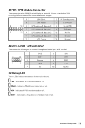
.... indicates booting device is not detected or fail. Please refer to the TPM security platform manual for TPM (Trusted Platform Module). CPU - VGA - Overview of the motherboard. DRAM - indicates GPU is not detected or fail. JTPM1: TPM Module Connector This connector is for more details and usages. 1 LPC Clock 2 3V Standby power 3 LPC Reset 4 3.3V Power 2 14 5 LPC address & data pin0 6 Serial IRQ 7 LPC...
.... indicates booting device is not detected or fail. Please refer to the TPM security platform manual for TPM (Trusted Platform Module). CPU - VGA - Overview of the motherboard. DRAM - indicates GPU is not detected or fail. JTPM1: TPM Module Connector This connector is for more details and usages. 1 LPC Clock 2 3V Standby power 3 LPC Reset 4 3.3V Power 2 14 5 LPC address & data pin0 6 Serial IRQ 7 LPC...

User Manual
Page 14
... and adjust fan speed with speed control signal. Select PWM mode or DC mode There are working properly after switching the PWM/ DC mode. DC Mode fan connectors control fan speed by changing voltage. Default PWM Mode fan connectors 1 Default DC Mode fan connectors CPU_FAN1 1 SYS_FAN1 Switching fan mode and adjusting fan speed You can switch between PWM mode and DC mode and adjust fan speed in relation to adjust fan speed in BIOS > HARDWARE MONITOR. Pin definition of fan connectors PWM Mode pin definition 1 Ground 2 +12V 3 Sense 4 Speed Control Signal DC Mode pin definition...
... and adjust fan speed with speed control signal. Select PWM mode or DC mode There are working properly after switching the PWM/ DC mode. DC Mode fan connectors control fan speed by changing voltage. Default PWM Mode fan connectors 1 Default DC Mode fan connectors CPU_FAN1 1 SYS_FAN1 Switching fan mode and adjusting fan speed You can switch between PWM mode and DC mode and adjust fan speed in relation to adjust fan speed in BIOS > HARDWARE MONITOR. Pin definition of fan connectors PWM Mode pin definition 1 Ground 2 +12V 3 Sense 4 Speed Control Signal DC Mode pin definition...
User Manual
Page 15
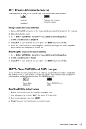
... event Using chassis intrusion detector 1. Press F10 to save and exit and then press the Enter key to select Yes. 6. Once the chassis cover is opened again, a warning message will be displayed on screen when the computer is external powered from JBAT1. 4. Keep Data (default) Clear CMOS/ Reset BIOS Resetting BIOS to BIOS > SETTINGS > Security > Chassis Intrusion Configuration. 2. Go to default values 1. JBAT1: Clear CMOS (Reset BIOS) Jumper There is CMOS memory onboard that is turned on. Go to Enabled...
... event Using chassis intrusion detector 1. Press F10 to save and exit and then press the Enter key to select Yes. 6. Once the chassis cover is opened again, a warning message will be displayed on screen when the computer is external powered from JBAT1. 4. Keep Data (default) Clear CMOS/ Reset BIOS Resetting BIOS to BIOS > SETTINGS > Security > Chassis Intrusion Configuration. 2. Go to default values 1. JBAT1: Clear CMOS (Reset BIOS) Jumper There is CMOS memory onboard that is turned on. Go to Enabled...
User Manual
Page 16
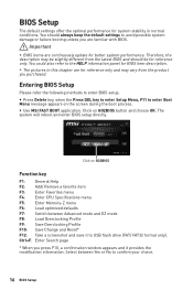
... Change and Reset* F12: Take a screenshot and save it provides the modification information. Entering BIOS Setup Please refer the following methods to enter Boot Menu message appears on the screen during the boot process. Ctrl+F: Enter Search page * When you purchased. y Use MSI FAST BOOT application. Click on GO2BIOS Function key F1: General Help F2: Add/ Remove a favorite item F3: Enter Favorites menu F4: Enter CPU Specifications menu F5: Enter Memory-Z menu F6: Load optimized defaults F7: Switch...
... Change and Reset* F12: Take a screenshot and save it provides the modification information. Entering BIOS Setup Please refer the following methods to enter Boot Menu message appears on the screen during the boot process. Ctrl+F: Enter Search page * When you purchased. y Use MSI FAST BOOT application. Click on GO2BIOS Function key F1: General Help F2: Add/ Remove a favorite item F3: Enter Favorites menu F4: Enter CPU Specifications menu F5: Enter Memory-Z menu F6: Load optimized defaults F7: Switch...
User Manual
Page 17
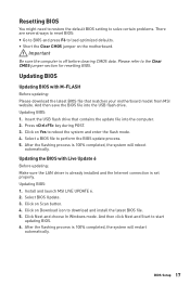
... the Clear CMOS jumper section for resetting BIOS. Select BIOS Update. 3. After the flashing process is set properly. Click on Yes to download and install the latest BIOS file. 5. Please refer to perform the BIOS update process. 5. Insert the USB flash drive that matches your motherboard model from MSI website. And then click Next and Start to load optimized defaults. Click Next and choose In Windows mode. Updating BIOS: 1. Click on Download icon to reboot the system and enter the flash mode. 4. Resetting BIOS...
... the Clear CMOS jumper section for resetting BIOS. Select BIOS Update. 3. After the flashing process is set properly. Click on Yes to download and install the latest BIOS file. 5. Please refer to perform the BIOS update process. 5. Insert the USB flash drive that matches your motherboard model from MSI website. And then click Next and Start to load optimized defaults. Click Next and choose In Windows mode. Updating BIOS: 1. Click on Download icon to reboot the system and enter the flash mode. 4. Resetting BIOS...
User Manual
Page 18
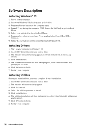
... case. 4. Insert the Windows® 10 disc into Boot Menu. 5. Click Install button. 5. Restart your optical drive. 3. Press F11 key during the computer POST (Power-On Self Test) to finish. 7. The software installation will then be in progress, after it has finished it will automatically appear. 3. Click Install button. 6. Software Description Installing Windows® 10 1. Press the Restart button on the computer. 2. Select your optical drive from CD or DVD... Start...
... case. 4. Insert the Windows® 10 disc into Boot Menu. 5. Click Install button. 5. Restart your optical drive. 3. Press F11 key during the computer POST (Power-On Self Test) to finish. 7. The software installation will then be in progress, after it has finished it will automatically appear. 3. Click Install button. 6. Software Description Installing Windows® 10 1. Press the Restart button on the computer. 2. Select your optical drive from CD or DVD... Start...
User Manual
Page 106
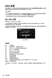
...;置� 注意 y BIOS BIOS y 进� BIOS 设置 BIOS 设置� y Press DEL key to enter Setup Menu, F11 to enter Boot Menu Delete 键� y 使用 MSI FAST BOOT GO2BIOS OK BIOS 设置� 点击 GO2BIOS 功能键 F1 F2 F3: 进入 Favorites F4: 进入 CPU F5: 进入 Memory-Z 菜单 F6 F7 EZ...
...;置� 注意 y BIOS BIOS y 进� BIOS 设置 BIOS 设置� y Press DEL key to enter Setup Menu, F11 to enter Boot Menu Delete 键� y 使用 MSI FAST BOOT GO2BIOS OK BIOS 设置� 点击 GO2BIOS 功能键 F1 F2 F3: 进入 Favorites F4: 进入 CPU F5: 进入 Memory-Z 菜单 F6 F7 EZ...

User Manual
Page 145
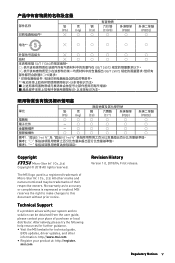
... can radiate radio frequency energy and, if not installed and used in accordance with part 15 of the FCC Rules. If this device must accept any interference received, including interference that may cause harmful interference to radio communications. CE Conformity Products bearing the CE marking comply with the same or equivalent type recommended by turning the equipment...
... can radiate radio frequency energy and, if not installed and used in accordance with part 15 of the FCC Rules. If this device must accept any interference received, including interference that may cause harmful interference to radio communications. CE Conformity Products bearing the CE marking comply with the same or equivalent type recommended by turning the equipment...
User Manual
Page 149
...MSI logo used is expressed or implied. All other information: http://www.msi.com y Register your place of their respective owners. No warranty as to this document without prior notice. Alternatively, please try the following help resources for technical guide, BIOS updates, driver updates, and other marks and names mentioned may be obtained from the user guide..., please contact your product at: http://register. msi.com Revision History Version 1.0, 2018/...
...MSI logo used is expressed or implied. All other information: http://www.msi.com y Register your place of their respective owners. No warranty as to this document without prior notice. Alternatively, please try the following help resources for technical guide, BIOS updates, driver updates, and other marks and names mentioned may be obtained from the user guide..., please contact your product at: http://register. msi.com Revision History Version 1.0, 2018/...


