User Manual
Page 1
PRO H610M-G WIFI DDR4 Motherboard User Guide Manuel d'utilisation Benutzerhandbuch
PRO H610M-G WIFI DDR4 Motherboard User Guide Manuel d'utilisation Benutzerhandbuch

User Manual
Page 2
... Slot (Key M 13 SATA5~8: SATA 6Gb/s Connectors 13 CPU_PWR1, ATX_PWR1: Power Connectors 14 JAUD1: Front Audio Connector 15 CPU_FAN1, SYS_FAN1: Fan Connectors 15 JCI1: Chassis Intrusion Connector 16 JBAT1: Clear CMOS (Reset BIOS) Jumper 16 JUSB2: USB 3.2 Gen 1 Connector 17 JUSB1: USB 2.0 Connector 17 JTPM1: TPM Module Connector 18 JRGB1: RGB LED connector 18 JRAINBOW1~2: Addressable RGB LED connectors 19 EZ Debug LED...19 1 Thank you for purchasing the MSI® motherboard. This User Guide gives information about board layout, component overview, BIOS setup and software installation...
... Slot (Key M 13 SATA5~8: SATA 6Gb/s Connectors 13 CPU_PWR1, ATX_PWR1: Power Connectors 14 JAUD1: Front Audio Connector 15 CPU_FAN1, SYS_FAN1: Fan Connectors 15 JCI1: Chassis Intrusion Connector 16 JBAT1: Clear CMOS (Reset BIOS) Jumper 16 JUSB2: USB 3.2 Gen 1 Connector 17 JUSB1: USB 2.0 Connector 17 JTPM1: TPM Module Connector 18 JRGB1: RGB LED connector 18 JRAINBOW1~2: Addressable RGB LED connectors 19 EZ Debug LED...19 1 Thank you for purchasing the MSI® motherboard. This User Guide gives information about board layout, component overview, BIOS setup and software installation...

User Manual
Page 4
... same voltage as injury to the user. ∙∙If you need help during any installation step, please consult a certified computer technician. ∙∙Always turn off the power supply and unplug the power cord from the power outlet before installing or removing any of the following instructions to ensure successful computer assembly. ∙∙Ensure that all components are securely connected...
... same voltage as injury to the user. ∙∙If you need help during any installation step, please consult a certified computer technician. ∙∙Always turn off the power supply and unplug the power cord from the power outlet before installing or removing any of the following instructions to ensure successful computer assembly. ∙∙Ensure that all components are securely connected...
User Manual
Page 5
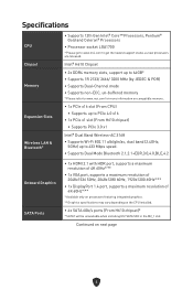
... new processors are released. Specifications CPU Chipset Memory Expansion Slots Wireless LAN & Bluetooth® ∙∙Supports 12th Gen Intel® Core™ Processors, Pentium® Gold and Celeron® Processors ∙∙Processor socket LGA1700 * Please go to www.msi.com to 433 Mbps speed. ∙∙Supports Dual Mode Bluetooth 2.1,2.1+EDR,3.0,4.0,BLE,4.2 Onboard Graphics SATA Ports ∙∙1x HDMI 2.1 with HDR port, supports a maximum resolution of 4K 60Hz*/** ∙∙1x VGA port, supports a maximum...
... new processors are released. Specifications CPU Chipset Memory Expansion Slots Wireless LAN & Bluetooth® ∙∙Supports 12th Gen Intel® Core™ Processors, Pentium® Gold and Celeron® Processors ∙∙Processor socket LGA1700 * Please go to www.msi.com to 433 Mbps speed. ∙∙Supports Dual Mode Bluetooth 2.1,2.1+EDR,3.0,4.0,BLE,4.2 Onboard Graphics SATA Ports ∙∙1x HDMI 2.1 with HDR port, supports a maximum resolution of 4K 60Hz*/** ∙∙1x VGA port, supports a maximum...

User Manual
Page 6
... installing M.2 SATA SSD in the M2_1 slot. Audio Realtek® ALC897 Codec ∙∙7.1-Channel High Definition Audio LAN ∙∙1x Intel® I219V 1Gbps LAN controller Power Connectors ∙∙1x 24-pin ATX main power connector ∙∙1x 8-pin ATX 12V power connector Internal USB Connectors ∙∙1x USB 3.2 Gen 1 5Gbps connector (From H610 chipset) • Supports additional 2 USB 3.2 Gen 1 5Gbps ports ∙∙1x USB 2.0 connector (From H610 chipset) • Supports additional 2 USB 2.0 ports Fan Connectors ∙∙1x 4-pin CPU fan...
... installing M.2 SATA SSD in the M2_1 slot. Audio Realtek® ALC897 Codec ∙∙7.1-Channel High Definition Audio LAN ∙∙1x Intel® I219V 1Gbps LAN controller Power Connectors ∙∙1x 24-pin ATX main power connector ∙∙1x 8-pin ATX 12V power connector Internal USB Connectors ∙∙1x USB 3.2 Gen 1 5Gbps connector (From H610 chipset) • Supports additional 2 USB 3.2 Gen 1 5Gbps ports ∙∙1x USB 2.0 connector (From H610 chipset) • Supports additional 2 USB 2.0 ports Fan Connectors ∙∙1x 4-pin CPU fan...

User Manual
Page 7
... Panel Connectors I/O Controller Hardware Monitor Form Factor BIOS Features Software Continued from previous page ∙∙1x HDMI port ∙∙1x VGA port ∙∙1x DisplayPort port ∙∙1x PS/2 keyboard/ mouse combo port ∙∙4x USB 2.0 Type-A ports (From H610 chipset) ∙∙2x USB 3.2 Gen 1 5Gbps Type-A ports (From H610 chipset) ∙∙1x LAN (RJ45) jack ∙∙3x audio jacks NUVOTON NCT6687D-M Controller Chip ∙∙CPU/ System/ Chipset temperature...
... Panel Connectors I/O Controller Hardware Monitor Form Factor BIOS Features Software Continued from previous page ∙∙1x HDMI port ∙∙1x VGA port ∙∙1x DisplayPort port ∙∙1x PS/2 keyboard/ mouse combo port ∙∙4x USB 2.0 Type-A ports (From H610 chipset) ∙∙2x USB 3.2 Gen 1 5Gbps Type-A ports (From H610 chipset) ∙∙1x LAN (RJ45) jack ∙∙3x audio jacks NUVOTON NCT6687D-M Controller Chip ∙∙CPU/ System/ Chipset temperature...

User Manual
Page 11
... the cooling fans work properly to the documentation in the heatsink/ cooler package for more details about installation. 10 A CPU heatsink is not installed, always protect the CPU socket pins by covering the socket with the CPU before installing or removing the CPU. ∙∙Please retain the CPU protective cap after installing the processor. MSI will deal with Return Merchandise Authorization (RMA) requests if only the motherboard comes with...
... the cooling fans work properly to the documentation in the heatsink/ cooler package for more details about installation. 10 A CPU heatsink is not installed, always protect the CPU socket pins by covering the socket with the CPU before installing or removing the CPU. ∙∙Please retain the CPU protective cap after installing the processor. MSI will deal with Return Merchandise Authorization (RMA) requests if only the motherboard comes with...
User Manual
Page 12
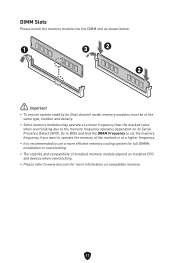
... DIMMs installation or overclocking. ∙∙The stability and compatibility of installed memory module depend on installed CPU and devices when overclocking. ∙∙Please refer to the memory frequency operates dependent on compatible memory. 11 DIMM Slots Please install the memory module into the DIMM slot as shown below. 1 3 2 2 ⚠⚠Important ∙∙To ensure system stability for Dual channel mode, memory modules must be of the same type, number...
... DIMMs installation or overclocking. ∙∙The stability and compatibility of installed memory module depend on installed CPU and devices when overclocking. ∙∙Please refer to the memory frequency operates dependent on compatible memory. 11 DIMM Slots Please install the memory module into the DIMM slot as shown below. 1 3 2 2 ⚠⚠Important ∙∙To ensure system stability for Dual channel mode, memory modules must be of the same type, number...

User Manual
Page 13
... the cable to connect power button/ reset button. Power Switch/ Reset Switch headers allow you need to use a tool such as MSI Graphics Card Bolster to support its weight to prevent deformation of the hard disk. To connect the cables from the power outlet. JFP1, JFP2: Front Panel Connectors The JFP1 connector controls the power on, power reset, and the LEDs on the PC case, and HDD LED header indicates the activity of the slot. ∙∙When adding or removing expansion cards, always turn off the power supply...
... the cable to connect power button/ reset button. Power Switch/ Reset Switch headers allow you need to use a tool such as MSI Graphics Card Bolster to support its weight to prevent deformation of the hard disk. To connect the cables from the power outlet. JFP1, JFP2: Front Panel Connectors The JFP1 connector controls the power on, power reset, and the LEDs on the PC case, and HDD LED header indicates the activity of the slot. ∙∙When adding or removing expansion cards, always turn off the power supply...

User Manual
Page 17
...Resetting the chassis intrusion warning 1. Set Chassis Intrusion to BIOS > SETTINGS > Security > Chassis Intrusion Configuration. 4. Remove the jumper cap from a battery located on the chassis. 2. Go to Reset. 3. Plug the power cord and Power on . Set Chassis Intrusion to select Yes. Press F10 to save and exit and then press the Enter key to Enabled. 5. Connect the JCI1 connector to connect the chassis intrusion switch cable. JCI1: Chassis Intrusion Connector This connector allows you want to clear the system configuration, set the jumpers to BIOS > SETTINGS...
...Resetting the chassis intrusion warning 1. Set Chassis Intrusion to BIOS > SETTINGS > Security > Chassis Intrusion Configuration. 4. Remove the jumper cap from a battery located on the chassis. 2. Go to Reset. 3. Plug the power cord and Power on . Set Chassis Intrusion to select Yes. Press F10 to save and exit and then press the Enter key to Enabled. 5. Connect the JCI1 connector to connect the chassis intrusion switch cable. JCI1: Chassis Intrusion Connector This connector allows you want to clear the system configuration, set the jumpers to BIOS > SETTINGS...

User Manual
Page 19
... power outlet before installing or removing the RGB LED strip. ∙∙Please use MSI's software to connect the 5050 RGB LED strips 12V. JTPM1: TPM Module Connector This connector is for more details and usages. 2 12 1 11 Pin Signal Name Pin Signal Name 1 SPI Power 2 SPI Chip Select 3 Master In Slave Out (SPI Data) 4 Master Out Slave In (SPI Data) 5 Reserved 6 SPI Clock 7 Ground 8 SPI Reset...
... power outlet before installing or removing the RGB LED strip. ∙∙Please use MSI's software to connect the 5050 RGB LED strips 12V. JTPM1: TPM Module Connector This connector is for more details and usages. 2 12 1 11 Pin Signal Name Pin Signal Name 1 SPI Power 2 SPI Chip Select 3 Master In Slave Out (SPI Data) 4 Master Out Slave In (SPI Data) 5 Reserved 6 SPI Clock 7 Ground 8 SPI Reset...

User Manual
Page 20
... result in damage to the LED strip. ⚠⚠Important ∙∙The JRAINBOW connector supports up to 200 LEDs. ∙∙Always turn off the power supply and unplug the power cord from the power outlet before installing or removing the RGB LED strip. ∙∙Please use MSI's software to connect the WS2812B Individually Addressable RGB LED strips 5V. BOOT - indicates booting device is not detected or fail. DRAM -
... result in damage to the LED strip. ⚠⚠Important ∙∙The JRAINBOW connector supports up to 200 LEDs. ∙∙Always turn off the power supply and unplug the power cord from the power outlet before installing or removing the RGB LED strip. ∙∙Please use MSI's software to connect the WS2812B Individually Addressable RGB LED strips 5V. BOOT - indicates booting device is not detected or fail. DRAM -

User Manual
Page 21
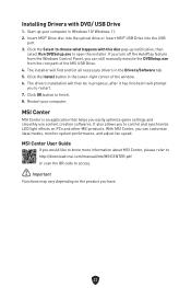
... MSI DUI MSI DUI (Driver Utility Installer) needs to boot from the Boot Menu. 6. Press F11 key during the computer POST (Power-On Self Test) to the MSI Terms of Use check box, and then click Next. 20 message. Follow the instructions on the computer. 2. Insert the Windows 10/ Windows 11 installation disc/USB into Boot Menu. 5. Select the Windows 10/ Windows 11 installation disc/USB from CD or DVD... Installing Drivers with DVD/ USB Drive section. 1. Start up automatically. 4. Select Start > Settings > Windows Update...
... MSI DUI MSI DUI (Driver Utility Installer) needs to boot from the Boot Menu. 6. Press F11 key during the computer POST (Power-On Self Test) to the MSI Terms of Use check box, and then click Next. 20 message. Follow the instructions on the computer. 2. Insert the Windows 10/ Windows 11 installation disc/USB into Boot Menu. 5. Select the Windows 10/ Windows 11 installation disc/USB from CD or DVD... Installing Drivers with DVD/ USB Drive section. 1. Start up automatically. 4. Select Start > Settings > Windows Update...
User Manual
Page 23
.... Click the Select to open the installer. Click the Install button in the Drivers/Software tab. 5. MSI Center User Guide If you have. 22 Start up notification, then select Run DVDSetup.exe to choose what happens with DVD/ USB Drive 1. MSI Center MSI Center is an application that helps you can customize ideal modes, monitor system performance, and adjust fan speed. The drivers installation will then be in progress, after...
.... Click the Select to open the installer. Click the Install button in the Drivers/Software tab. 5. MSI Center User Guide If you have. 22 Start up notification, then select Run DVDSetup.exe to choose what happens with DVD/ USB Drive 1. MSI Center MSI Center is an application that helps you can customize ideal modes, monitor system performance, and adjust fan speed. The drivers installation will then be in progress, after...
User Manual
Page 24
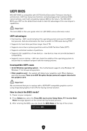
... a GOP/UEFI compatible graphics card or using integrated graphics from CPU for hard drive partitions larger than 2 TB. ∙∙Supports more than 4 primary partitions with UEFI (Unified Extensible Firmware Interface) architecture. the system will completely replace BIOS in this motherboard supports only Windows 10/ Windows 11 64-bit operating system. ∙∙ Older graphics card - Press Delete key, when the Press DEL key to enter Setup Menu, F11 to check the BIOS mode? 1. How to enter Boot Menu message appears...
... a GOP/UEFI compatible graphics card or using integrated graphics from CPU for hard drive partitions larger than 2 TB. ∙∙Supports more than 4 primary partitions with UEFI (Unified Extensible Firmware Interface) architecture. the system will completely replace BIOS in this motherboard supports only Windows 10/ Windows 11 64-bit operating system. ∙∙ Older graphics card - Press Delete key, when the Press DEL key to enter Setup Menu, F11 to check the BIOS mode? 1. How to enter Boot Menu message appears...
User Manual
Page 25
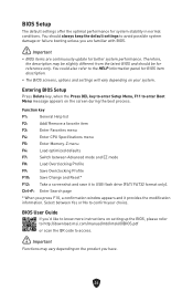
... modification information. BIOS User Guide If you'd like to know more instructions on the product you are familiar with BIOS. ⚠⚠Important ∙∙BIOS items are continuously update for system stability in normal conditions. Function key F1: General Help list F2: Add/ Remove a favorite item F3: Enter Favorites menu F4: Enter CPU Specifications menu F5: Enter Memory-Z menu F6: Load optimized defaults F7: Switch between Yes or No to USB flash drive (FAT...
... modification information. BIOS User Guide If you'd like to know more instructions on the product you are familiar with BIOS. ⚠⚠Important ∙∙BIOS items are continuously update for system stability in normal conditions. Function key F1: General Help list F2: Add/ Remove a favorite item F3: Enter Favorites menu F4: Enter CPU Specifications menu F5: Enter Memory-Z menu F6: Load optimized defaults F7: Switch between Yes or No to USB flash drive (FAT...
User Manual
Page 26
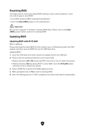
... motherboard model from MSI website. Click the M-FLASH button and click on Yes to start recovering BIOS. 5. When prompted click on Yes to reboot the system. 3. Please refer the following methods to enter flash mode. • Reboot and press Ctrl + F5 key during POST to enter BIOS. Updating BIOS Updating BIOS with M-FLASH Before updating: Please download the latest BIOS file that contains the update file into the USB flash drive. And then save the BIOS file into the USB port. 2. Select a BIOS file...
... motherboard model from MSI website. Click the M-FLASH button and click on Yes to start recovering BIOS. 5. When prompted click on Yes to reboot the system. 3. Please refer the following methods to enter flash mode. • Reboot and press Ctrl + F5 key during POST to enter BIOS. Updating BIOS Updating BIOS with M-FLASH Before updating: Please download the latest BIOS file that contains the update file into the USB flash drive. And then save the BIOS file into the USB port. 2. Select a BIOS file...

User Manual
Page 60
Fonctions spéciales Fonctions MSI Center • Mystic Light • User Scenario • Hardware Monitor • Frozr AI Cooling • True Color • Live Update • Speed Up • Super Charger Audio • Audio Boost LED • Mystic Light Extension (RAINBOW/ RGB) • Mystic Light SYNC • Ambient Devices Support • EZ DEBUG LED Performance • Memory Boost • Core Boost • Lightning Gen 4 PCI-E Slot Protection • PCI-E Steel Armor Expérience • Click BIOS 5 • EZ M.2 Clip • CPU Cooler Tuning 7
Fonctions spéciales Fonctions MSI Center • Mystic Light • User Scenario • Hardware Monitor • Frozr AI Cooling • True Color • Live Update • Speed Up • Super Charger Audio • Audio Boost LED • Mystic Light Extension (RAINBOW/ RGB) • Mystic Light SYNC • Ambient Devices Support • EZ DEBUG LED Performance • Memory Boost • Core Boost • Lightning Gen 4 PCI-E Slot Protection • PCI-E Steel Armor Expérience • Click BIOS 5 • EZ M.2 Clip • CPU Cooler Tuning 7

User Manual
Page 203
... boot from CD or DVD 7 Windows 10/ Windows 11。 使用 MSI DUI Internet 安装 MSI DUI (Driver Utility Installer Internet Installing Drivers with DVD/ USB Drive 部分。 1 Windows 10/ Windows 11。 2. 选择 Start > Settings > Windows Update 3. MSI Center 请通过 www.msi.com 安装 Windows 10/ Windows 11 1 2. 将 Windows 10/ Windows 11 U 3 Restart 按钮。 4. 计算机 POST F11 5 Windows 10/ Windows 11 U 盘。 6 Press any key...
... boot from CD or DVD 7 Windows 10/ Windows 11。 使用 MSI DUI Internet 安装 MSI DUI (Driver Utility Installer Internet Installing Drivers with DVD/ USB Drive 部分。 1 Windows 10/ Windows 11。 2. 选择 Start > Settings > Windows Update 3. MSI Center 请通过 www.msi.com 安装 Windows 10/ Windows 11 1 2. 将 Windows 10/ Windows 11 U 3 Restart 按钮。 4. 计算机 POST F11 5 Windows 10/ Windows 11 U 盘。 6 Press any key...

User Manual
Page 218
... technical guide, BIOS updates, driver updates, and other marks and names mentioned may be obtained from the user guide, please contact your product at: http://register.msi.com Revision History ∙∙Version 1.2, 2022/06, first release for PRO H610M-G WIFI DDR4. All other information: http://www.msi.com ∙∙Register your place of Micro-Star Int'l Co., Ltd. The MSI logo used is expressed or...
... technical guide, BIOS updates, driver updates, and other marks and names mentioned may be obtained from the user guide, please contact your product at: http://register.msi.com Revision History ∙∙Version 1.2, 2022/06, first release for PRO H610M-G WIFI DDR4. All other information: http://www.msi.com ∙∙Register your place of Micro-Star Int'l Co., Ltd. The MSI logo used is expressed or...

