
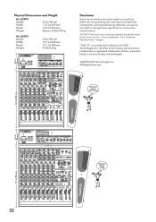
Spec Sheet
Page 2
... BAL U PRE 2 FX +15 BAL SPRING STAGE TREMOLD ROOM FLANGER+REV FLANGER THEATER ROTARY ECHO ECHO+REV STEREO DELAY 16 1 15 14 2 3 CATHEDRAL 13 4 STUDIO CHORUS CHORUS+REV HALL 12 5 11 6 10 9 87 VARIATIONS FX INPUT LEVEL FX OL MAX FX BYPASS CONTROL ROOM MAIN CD/ MIX TAPE ALT 3-4 SOURCE SELECT MAX CTRL ROOM/ PHONES TAPE TO MAIN PFL AFL SOLO MODE MASTER U AUX SEND...
... BAL U PRE 2 FX +15 BAL SPRING STAGE TREMOLD ROOM FLANGER+REV FLANGER THEATER ROTARY ECHO ECHO+REV STEREO DELAY 16 1 15 14 2 3 CATHEDRAL 13 4 STUDIO CHORUS CHORUS+REV HALL 12 5 11 6 10 9 87 VARIATIONS FX INPUT LEVEL FX OL MAX FX BYPASS CONTROL ROOM MAIN CD/ MIX TAPE ALT 3-4 SOURCE SELECT MAX CTRL ROOM/ PHONES TAPE TO MAIN PFL AFL SOLO MODE MASTER U AUX SEND...

Owners Manual
Page 2
.... The U.S. Ear plugs or protectors in the ear canals or over the ears must be moved with Class-I .P.s Loudest parts at plugs, convenience receptacles, and the point where they exit from tip-over. SAFETY INSTRUCTIONS 1. Keep these instructions. 2. Do not install near water. 6. Do not defeat the safety purpose of the limits set out in operation. Quick stops, excessive...
.... The U.S. Ear plugs or protectors in the ear canals or over the ears must be moved with Class-I .P.s Loudest parts at plugs, convenience receptacles, and the point where they exit from tip-over. SAFETY INSTRUCTIONS 1. Keep these instructions. 2. Do not install near water. 6. Do not defeat the safety purpose of the limits set out in operation. Quick stops, excessive...
Owners Manual
Page 3
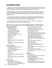
CONTENTS SAFETY INSTRUCTIONS 2 Getting Started 4 Introduction 6 Hookup Diagrams 7 MIX FX Series Features 8 CHANNEL INPUTS 8 CHANNEL CONTROLS 9 AUXILIARY 9 CONTROL ROOM SECTION 11 AUXILIARY SECTION 13 INTERNAL EFFECTS 14 MAIN MIX, SUBS, and POWER LEDs 14 FRONT PANEL CONNECTORS 15 REAR PANEL FEATURES 16 Appendix A: Service Information 18 Appendix B: Connections 20 Appendix C: MIX FX Series Specifications 21 Block Diagram Mix.220FX 23 Block Diagram Mix.260FX 24 TAPCO LIMITED WARRANTY 27 Don't forget to...
CONTENTS SAFETY INSTRUCTIONS 2 Getting Started 4 Introduction 6 Hookup Diagrams 7 MIX FX Series Features 8 CHANNEL INPUTS 8 CHANNEL CONTROLS 9 AUXILIARY 9 CONTROL ROOM SECTION 11 AUXILIARY SECTION 13 INTERNAL EFFECTS 14 MAIN MIX, SUBS, and POWER LEDs 14 FRONT PANEL CONNECTORS 15 REAR PANEL FEATURES 16 Appendix A: Service Information 18 Appendix B: Connections 20 Appendix C: MIX FX Series Specifications 21 Block Diagram Mix.220FX 23 Block Diagram Mix.260FX 24 TAPCO LIMITED WARRANTY 27 Don't forget to...

Owners Manual
Page 4
... LEVELS (Stereo Line Channels): 1. Repeat steps 1 through 4 for the remaining stereo channels. 4 Turn down the ALT 3/4 or SUB 1/2 faders, and the MAIN MIX faders. Turn down the channel strip GAIN, AUX SEND, and fader controls. 3. Connect your mixer to the AC socket on the PHANTOM POWER switch.) Connect line-level signal sources to the mono MIC or LINE input. Connect the power cord supplied with your microphones and instruments to the mixer: Connect microphones to the mono channel MIC INPUT jacks...
... LEVELS (Stereo Line Channels): 1. Repeat steps 1 through 4 for the remaining stereo channels. 4 Turn down the ALT 3/4 or SUB 1/2 faders, and the MAIN MIX faders. Turn down the channel strip GAIN, AUX SEND, and fader controls. 3. Connect your mixer to the AC socket on the PHANTOM POWER switch.) Connect line-level signal sources to the mono MIC or LINE input. Connect the power cord supplied with your microphones and instruments to the mixer: Connect microphones to the mono channel MIC INPUT jacks...

Owners Manual
Page 5
When powering up, turn on , and then turn the level controls back up. • When you shut down , turn the power off, make the changes, turn off any external amplifiers first. Please see the Safety Instructions on page 2 for prolonged periods. The box can also be turned into anything except speakers. • Never use guitar cables to connect amplifiers to speakers. • Before...
When powering up, turn on , and then turn the level controls back up. • When you shut down , turn the power off, make the changes, turn off any external amplifiers first. Please see the Safety Instructions on page 2 for prolonged periods. The box can also be turned into anything except speakers. • Never use guitar cables to connect amplifiers to speakers. • Before...
Owners Manual
Page 6
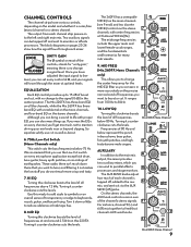
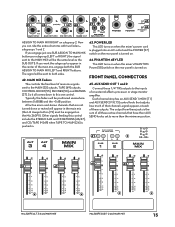
...; Stereo 1/4" Phones output • Internal digital effects section with effects select control, variations control, input level control, FX overload LED, and FX bypass switch • 1/4" Footswitch jack to bypass the internal effects, duplicates the FX bypass switch • Source select switches for Control Room/Phones output • Rotary Ctrl Room/Phones level control • Tape to Main switch • Solo mode switch (PFL/AFL) • Aux Return 1 level control with Main/Sub 1-2 assign switch • Aux Return...
...; Stereo 1/4" Phones output • Internal digital effects section with effects select control, variations control, input level control, FX overload LED, and FX bypass switch • 1/4" Footswitch jack to bypass the internal effects, duplicates the FX bypass switch • Source select switches for Control Room/Phones output • Rotary Ctrl Room/Phones level control • Tape to Main switch • Solo mode switch (PFL/AFL) • Aux Return 1 level control with Main/Sub 1-2 assign switch • Aux Return...

Owners Manual
Page 8
... balanced and TS unbalanced plugs from a signal connected to one cord), always use the left (mono) input and the right input. OL LED This handy LED (Light Emitting Diode) lets you Mix.2L20FX SteRreo Channel 2. MIC (MICROPHONE) INPUTS 3. L R 12kHz MUTE -15 +15 15 5U 6 ALT 3/4 2.5kHz 4. +4/-10 Switch -15 +15 U (Stereo channels only) Instead of a rotary gain 5 dB 10 OL 80Hz control, the stereo channels -15 +155 have trouble getting enough volume...
... balanced and TS unbalanced plugs from a signal connected to one cord), always use the left (mono) input and the right input. OL LED This handy LED (Light Emitting Diode) lets you Mix.2L20FX SteRreo Channel 2. MIC (MICROPHONE) INPUTS 3. L R 12kHz MUTE -15 +15 15 5U 6 ALT 3/4 2.5kHz 4. +4/-10 Switch -15 +15 U (Stereo channels only) Instead of a rotary gain 5 dB 10 OL 80Hz control, the stereo channels -15 +155 have trouble getting enough volume...
Owners Manual
Page 9
.... Turning it out makes the low stuff you 1 (MONO) MON +15 L want much of the channel's stereo signals. On the stereo channels, the AUX knob controls a mono sum of each channel is no change the center frequency for many 8 MID instruments. -15 +15 U 9. 0 CHANNEL CONTROLS The channel strips have adjusted the input signal to line- EQUALIZATION Each EQ control provides up . It ranges from each mixer. Two auxiliary signals can zero in bass...
.... Turning it out makes the low stuff you 1 (MONO) MON +15 L want much of the channel's stereo signals. On the stereo channels, the AUX knob controls a mono sum of each channel is no change the center frequency for many 8 MID instruments. -15 +15 U 9. 0 CHANNEL CONTROLS The channel strips have adjusted the input signal to line- EQUALIZATION Each EQ control provides up . It ranges from each mixer. Two auxiliary signals can zero in bass...

Owners Manual
Page 10
... a 0monitor send and feed the mono input of the signal appears in the PRE [12] switch to the main mi7x5Hz unaffected. OO Mix.220FX Mono Channel 10 For stereo channels, the BAL control works like a home stereo balance control, by PAN "routing" it is turned left and right channel signals pass through to use the 16 18 ALT 3-4 outputs [53]. In the center position, the left , the right...
... a 0monitor send and feed the mono input of the signal appears in the PRE [12] switch to the main mi7x5Hz unaffected. OO Mix.220FX Mono Channel 10 For stereo channels, the BAL control works like a home stereo balance control, by PAN "routing" it is turned left and right channel signals pass through to use the 16 18 ALT 3-4 outputs [53]. In the center position, the left , the right...
Owners Manual
Page 11
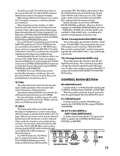
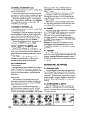
.... CD/TAPE Switch Push this switch to route the CD/TAPE input signal to the MAIN or ALT 3-4 SUB 1-2 (Mix.260FX) Switch mixes. The OL LED [5] lights continuously to the CONTROL ROOM outputs, PHONES, and METERS. That's called subgrouping. is one knob. Once you've got it ideal for the channel's signal. With the switch MAIN CD/ MIX TAPE ALT 3-4 SOURCE SELECT MAX CTRL ROOM/ PHONES TAPE TO MAIN SOLO MODE U AUX SEND RETURN...
.... CD/TAPE Switch Push this switch to route the CD/TAPE input signal to the MAIN or ALT 3-4 SUB 1-2 (Mix.260FX) Switch mixes. The OL LED [5] lights continuously to the CONTROL ROOM outputs, PHONES, and METERS. That's called subgrouping. is one knob. Once you've got it ideal for the channel's signal. With the switch MAIN CD/ MIX TAPE ALT 3-4 SOURCE SELECT MAX CTRL ROOM/ PHONES TAPE TO MAIN SOLO MODE U AUX SEND RETURN...

Owners Manual
Page 12
... on +5 SET the Mix.220FX), +2 27 to 0 in solo mode, you have a CD or Tape Deck connected to CLIP (+18) at the +10 LEVEL bottom (-20 on each channel. Use AFL mode during mixdown. If you can cause permanent hearing damage. Use the MAIN MIX controls to adjust the volume level. * We do not mean to the PHONES jack. Engaging a channel's SOLO switch will cause this switch to PFL mode If...
... on +5 SET the Mix.220FX), +2 27 to 0 in solo mode, you have a CD or Tape Deck connected to CLIP (+18) at the +10 LEVEL bottom (-20 on each channel. Use AFL mode during mixdown. If you can cause permanent hearing damage. Use the MAIN MIX controls to adjust the volume level. * We do not mean to the PHONES jack. Engaging a channel's SOLO switch will cause this switch to PFL mode If...
Owners Manual
Page 13
... Aux Send outputs. MASTER AUX SEND Knobs The Master AUX SEND knobs provide overall control for this switch is up . 29. It ranges from . RTRN TO AUX 1 Level Control This routes the FX RETURN signal to help assure you that while the listening levels are "in the CONTROL ROOM SOURCE SELECT, which feeds the CONTROL ROOM [55] and PHONES [50] outputs. The reason for the aux send levels, just before the MAIN MIX...
... Aux Send outputs. MASTER AUX SEND Knobs The Master AUX SEND knobs provide overall control for this switch is up . 29. It ranges from . RTRN TO AUX 1 Level Control This routes the FX RETURN signal to help assure you that while the listening levels are "in the CONTROL ROOM SOURCE SELECT, which feeds the CONTROL ROOM [55] and PHONES [50] outputs. The reason for the aux send levels, just before the MAIN MIX...
Owners Manual
Page 14
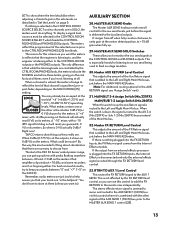
..., adjust the FX INPUT LEVEL knob until it to subgroups 1-2, engage the SUB ASSIGN TO MAIN MIX LEFT on the main mix or stage monitors. LOOK CLOSER The ALT 3-4 and SUB 1-2 signal is pushed in appear at the SUB OUTS (Mix.260FX only). Let's say you've got a drum kit using several channels and you are not using a reverb effect, a low number produces a short reverb time, and a larger number...
..., adjust the FX INPUT LEVEL knob until it to subgroups 1-2, engage the SUB ASSIGN TO MAIN MIX LEFT on the main mix or stage monitors. LOOK CLOSER The ALT 3-4 and SUB 1-2 signal is pushed in appear at the SUB OUTS (Mix.260FX only). Let's say you've got a drum kit using several channels and you are not using a reverb effect, a low number produces a short reverb time, and a larger number...
Owners Manual
Page 15
... signal sent to both the SUB ASSIGN TO MAIN MIX LEFT and RIGHT buttons. The output from these 1/4" TRS outputs to the inputs of all comes down or muted will be engaged on subgroup 2. Each channel strip has an AUX SEND 1 MON [11] and AUX SEND 2 FX [13] control knob that adjusts how much of that are not turned down to this control include the STEREO AUX...
... signal sent to both the SUB ASSIGN TO MAIN MIX LEFT and RIGHT buttons. The output from these 1/4" TRS outputs to the inputs of all comes down or muted will be engaged on subgroup 2. Each channel strip has an AUX SEND 1 MON [11] and AUX SEND 2 FX [13] control knob that adjusts how much of that are not turned down to this control include the STEREO AUX...
Owners Manual
Page 16
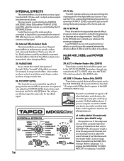
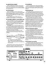
... XLR connectors provide a balanced line-level signal that if you have the tape inputs and outputs connected to the FX BYPASS switch illuminates when the bypass function is in ) via the Master FX RETURN level control [32]. 48. 1/4" MAIN OUT (Mix.260FX only) These 1/4" TRS jacks provide a balanced or unbalanced line-level signal, where your fully mixed stereo signal enters the real world. The signal will appear on the rear panel. Note that represent...
... XLR connectors provide a balanced line-level signal that if you have the tape inputs and outputs connected to the FX BYPASS switch illuminates when the bypass function is in ) via the Master FX RETURN level control [32]. 48. 1/4" MAIN OUT (Mix.260FX only) These 1/4" TRS jacks provide a balanced or unbalanced line-level signal, where your fully mixed stereo signal enters the real world. The signal will appear on the rear panel. Note that represent...
Owners Manual
Page 17
... or ribbon microphones, as channel direct outputs; Connect the detachable linecord (included in the box with the voltage required for an alternate mix. 57. CHANNEL INSERTS 1-4 (Mix.260FX only) These 1/4" TRS jacks provide a send and return point for the SUB 1 and 2 signals. The return (ring) is required to monitor the CD/TAPE Inputs (CD/TAPE switch pushed in your MIX FX Series mixer) to the power receptacle, and plug the...
... or ribbon microphones, as channel direct outputs; Connect the detachable linecord (included in the box with the voltage required for an alternate mix. 57. CHANNEL INSERTS 1-4 (Mix.260FX only) These 1/4" TRS jacks provide a send and return point for the SUB 1 and 2 signals. The return (ring) is required to monitor the CD/TAPE Inputs (CD/TAPE switch pushed in your MIX FX Series mixer) to the power receptacle, and plug the...

Owners Manual
Page 18
.... Replace the fuse drawer by prying it open with a small screwdriver. Reconnect the line cord and turn the POWER switch on . Bad Output • IS the MAIN MIX control turned up? • If it's a stereo pair, try turning it 's not the mixer. For example, if a left output is presumed dead, switch the left speaker is still dead, it on. • Is the red POWER LED illuminated? APPENDIX A: SERVICE...
.... Replace the fuse drawer by prying it open with a small screwdriver. Reconnect the line cord and turn the POWER switch on . Bad Output • IS the MAIN MIX control turned up? • If it's a stereo pair, try turning it 's not the mixer. For example, if a left output is presumed dead, switch the left speaker is still dead, it on. • Is the red POWER LED illuminated? APPENDIX A: SERVICE...
Owners Manual
Page 19
...fier for a warranty repair. Review the preceding troubleshooting suggestions. Repair Service for TAPCO mixers is available at 1-877-827-2669, 7 am to 5 pm PST. You must have a question about your mixer's serial number ready. Service for TAPCO mixers living outside the United States can obtain factory-authorized. 3. Call Tech Support at a factoryauthorized service center. Have your TAPCO Mixer? Keep this owner's manual.
...fier for a warranty repair. Review the preceding troubleshooting suggestions. Repair Service for TAPCO mixers is available at 1-877-827-2669, 7 am to 5 pm PST. You must have a question about your mixer's serial number ready. Service for TAPCO mixers living outside the United States can obtain factory-authorized. 3. Call Tech Support at a factoryauthorized service center. Have your TAPCO Mixer? Keep this owner's manual.
Owners Manual
Page 22
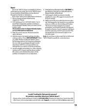
... BAL U PRE 2 FX +15 BAL SPRING STAGE TREMOLD ROOM FLANGER+REV FLANGER THEATER ROTARY ECHO ECHO+REV STEREO DELAY 16 1 15 14 2 3 CATHEDRAL 13 4 STUDIO 12 5 CHORUS CHORUS+REV HALL 11 6 10 7 98 VARIATIONS FX INPUT LEVEL FX OL MAX FX BYPASS CONTROL ROOM MAIN CD/ MIX TAPE ALT 3-4 SOURCE SELECT MAX CTRL ROOM/ PHONES TAPE TO MAIN PFL AFL SOLO MODE MASTER U AUX SEND...
... BAL U PRE 2 FX +15 BAL SPRING STAGE TREMOLD ROOM FLANGER+REV FLANGER THEATER ROTARY ECHO ECHO+REV STEREO DELAY 16 1 15 14 2 3 CATHEDRAL 13 4 STUDIO 12 5 CHORUS CHORUS+REV HALL 11 6 10 7 98 VARIATIONS FX INPUT LEVEL FX OL MAX FX BYPASS CONTROL ROOM MAIN CD/ MIX TAPE ALT 3-4 SOURCE SELECT MAX CTRL ROOM/ PHONES TAPE TO MAIN PFL AFL SOLO MODE MASTER U AUX SEND...
Owners Manual
Page 27
... Authorized TAPCO Service Centers. Products returned without a Service Request Number will be refused. 2. boxes or route numbers, please!). This warranty is within thirty days of the sales receipt is received for service time. 3. warrants all repairs performed for 90 days or for a period of any location within the U.S. The address of your return stree address (no responsibility for repair or replacement of...
... Authorized TAPCO Service Centers. Products returned without a Service Request Number will be refused. 2. boxes or route numbers, please!). This warranty is within thirty days of the sales receipt is received for service time. 3. warrants all repairs performed for 90 days or for a period of any location within the U.S. The address of your return stree address (no responsibility for repair or replacement of...


