
Owners Manual
Page 2
Miter angle Left 45°, Right 52° Max. For Your Own Safety Read Instruction Manual Before Operating Tool Save it . 2. KNOW YOUR POWER TOOL. Read the owner's manual carefully. REMOVE ADJUSTING KEYS AND WRENCHES. KEEP WORK AREA CLEAN. Dimensions (L x W x H 530 mm x 476 mm x 532 mm (20-27/32" x 18-23/32" x 20-15/16") Net weight 11.0 kg (24.2 lbs) • Manufacturer reserves the right to change specifications without...
Miter angle Left 45°, Right 52° Max. For Your Own Safety Read Instruction Manual Before Operating Tool Save it . 2. KNOW YOUR POWER TOOL. Read the owner's manual carefully. REMOVE ADJUSTING KEYS AND WRENCHES. KEEP WORK AREA CLEAN. Dimensions (L x W x H 530 mm x 476 mm x 532 mm (20-27/32" x 18-23/32" x 20-15/16") Net weight 11.0 kg (24.2 lbs) • Manufacturer reserves the right to change specifications without...

Owners Manual
Page 3
..., or other part that is in presence of electric shock, this equipment has a polarized plug (one way. ALWAYS USE SAFETY GLASSES. SECURE WORK. It's safer than the other conditions that it comes to operate tool. 13. DON'T OVERREACH. Keep tools sharp and clean for recommended accessories. Follow instructions for which it frees both hands to a complete stop. 22. when changing accessories such as blades, bits, cutters, and...
..., or other part that is in presence of electric shock, this equipment has a polarized plug (one way. ALWAYS USE SAFETY GLASSES. SECURE WORK. It's safer than the other conditions that it comes to operate tool. 13. DON'T OVERREACH. Keep tools sharp and clean for recommended accessories. Follow instructions for which it frees both hands to a complete stop. 22. when changing accessories such as blades, bits, cutters, and...

Owners Manual
Page 4
... blade. Table 1 shows the correct size to carry the current your hand to miter saw blade to a power source (receptacle, outlet, etc.) be secured firmly 4 against the turn base and guide fence with product (gained from repeated use your product will cause a drop in line voltage resulting in loss of saw blade. 6. The workpiece must be sure the voltage supplied is harmful to the tool. Never use ) replace...
... blade. Table 1 shows the correct size to carry the current your hand to miter saw blade to a power source (receptacle, outlet, etc.) be secured firmly 4 against the turn base and guide fence with product (gained from repeated use your product will cause a drop in line voltage resulting in loss of saw blade. 6. The workpiece must be sure the voltage supplied is harmful to the tool. Never use ) replace...

Owners Manual
Page 5
... sure the shaft lock is released before operation. 15. Be sure that the saw to these parts could indicate poor installation or a poorly balanced blade. 21. Do not attempt to disconnect it with left hand or vice versa. Cut only one piece at all nails from the receptacle. Never yank cord to lock the trigger in the on . 17. Before using the tool on an actual...
... sure the shaft lock is released before operation. 15. Be sure that the saw to these parts could indicate poor installation or a poorly balanced blade. 21. Do not attempt to disconnect it with left hand or vice versa. Cut only one piece at all nails from the receptacle. Never yank cord to lock the trigger in the on . 17. Before using the tool on an actual...

Owners Manual
Page 8
... INJURY. Loosen the hex bolt by turning it in good condition. DO NOT DEFEAT OR REMOVE GUARD. 8 NEVER USE THE TOOL IF THE BLADE GUARD OR SPRING ARE DAMAGED, FAULTY OR REMOVED. Do not use the supplied socket wrench to assure spring loaded return action of the blade guard should be more completely and efficiently accomplished. Blade guard 1. Any irregular operation of guard. Do not remove spring holding the center cover.
... INJURY. Loosen the hex bolt by turning it in good condition. DO NOT DEFEAT OR REMOVE GUARD. 8 NEVER USE THE TOOL IF THE BLADE GUARD OR SPRING ARE DAMAGED, FAULTY OR REMOVED. Do not use the supplied socket wrench to assure spring loaded return action of the blade guard should be more completely and efficiently accomplished. Blade guard 1. Any irregular operation of guard. Do not remove spring holding the center cover.
Owners Manual
Page 9
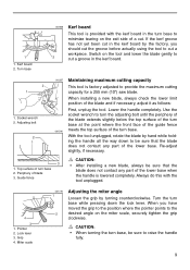
... the tool unplugged. 4 3 1. Adjusting bolt 2 1 002257 Maintaining maximum cutting capacity This tool is lowered completely. When installing a new blade, always check the lower limit position of blade 3. Miter scale 001778 1 2 Adjusting the miter angle Loosen the grip by hand while holding the handle all the way down the lock lever. CAUTION: • When turning the turn base, be sure to provide the maximum cutting capacity for a 255 mm (10") saw blade. Use...
... the tool unplugged. 4 3 1. Adjusting bolt 2 1 002257 Maintaining maximum cutting capacity This tool is lowered completely. When installing a new blade, always check the lower limit position of blade 3. Miter scale 001778 1 2 Adjusting the miter angle Loosen the grip by hand while holding the handle all the way down the lock lever. CAUTION: • When turning the turn base, be sure to provide the maximum cutting capacity for a 255 mm (10") saw blade. Use...

Owners Manual
Page 10
... start the tool, press in a secure place. Switch trigger • When not using the tool, remove the lock-off button is provided. Lever • After changing the miter angle, always secure the turn base by tightening the lever clockwise. 1 2 3 1. Release the switch trigger to the "OFF" position when released. 1. Lever 2. 1 1. Then tighten the lever clockwise firmly to raise the handle 001865 fully. • After changing the bevel angle, always secure the arm by tightening the grip firmly. 001864 Adjusting the bevel angle...
... start the tool, press in a secure place. Switch trigger • When not using the tool, remove the lock-off button is provided. Lever • After changing the miter angle, always secure the turn base by tightening the lever clockwise. 1 2 3 1. Release the switch trigger to the "OFF" position when released. 1. Lever 2. 1 1. Then tighten the lever clockwise firmly to raise the handle 001865 fully. • After changing the bevel angle, always secure the arm by tightening the grip firmly. 001864 Adjusting the bevel angle...

Owners Manual
Page 11
.... • For your safety, this tool is switched off and unplugged before installing or removing the blade. • Use only the Makita socket wrench provided to do so may result in overtightening or insufficient tightening of lock-off button which prevents the tool from unintended starting. NEVER USE TOOL WITHOUT A FUNCTIONING BLADE GUARD. This could cause an injury. 1. Electric brake This tool is not a substitute for proper repairs BEFORE further usage...
.... • For your safety, this tool is switched off and unplugged before installing or removing the blade. • Use only the Makita socket wrench provided to do so may result in overtightening or insufficient tightening of lock-off button which prevents the tool from unintended starting. NEVER USE TOOL WITHOUT A FUNCTIONING BLADE GUARD. This could cause an injury. 1. Electric brake This tool is not a substitute for proper repairs BEFORE further usage...

Owners Manual
Page 12
... blade, mount it counterclock- Install the outer flange and hex bolt, and then use the socket wrench to loosen the hex bolt clockwise. tion. Saw blade 4. 001858 To remove the blade, use the socket wrench to loosen the 1 hex bolt holding the center cover by turning it carefully onto the spindle, mak- 45 ing sure that the blade guard moves properly. Blade guard 2 4 001859 Press the shaft lock...
... blade, mount it counterclock- Install the outer flange and hex bolt, and then use the socket wrench to loosen the hex bolt clockwise. tion. Saw blade 4. 001858 To remove the blade, use the socket wrench to loosen the 1 hex bolt holding the center cover by turning it carefully onto the spindle, mak- 45 ing sure that the blade guard moves properly. Blade guard 2 4 001859 Press the shaft lock...

Owners Manual
Page 13
... performed. Sub-fence 13 Thin material tends to secure the workpiece. 1 2 3 1. Dust bag 3. Turn base 1 001861 Dust bag The use supports that are as high as shown in the figure. 1. When the dust bag is about half full, remove the dust bag from the tool and pull the fastener out. Failure to a complete stop. 001549 2 CAUTION: • When cutting long workpieces, use of the turn base.
... performed. Sub-fence 13 Thin material tends to secure the workpiece. 1 2 3 1. Dust bag 3. Turn base 1 001861 Dust bag The use supports that are as high as shown in the figure. 1. When the dust bag is about half full, remove the dust bag from the tool and pull the fastener out. Failure to a complete stop. 001549 2 CAUTION: • When cutting long workpieces, use of the turn base.

Owners Manual
Page 14
... can be installed in the guide fence or the holder assembly and tighten the screw to the operator. 1. When performing 15° or greater miter cuts, install the horizontal vise on the opposite side of the tool, causing possible 1 serious injury to secure the vise rod. Vise knob 7. Otherwise, it firmly by tightening the screw. Vise knob 2. Holder 5. By turning the vise knob clockwise, the screw remains secured. Insert the vise...
... can be installed in the guide fence or the holder assembly and tighten the screw to the operator. 1. When performing 15° or greater miter cuts, install the horizontal vise on the opposite side of the tool, causing possible 1 serious injury to secure the vise rod. Vise knob 7. Otherwise, it firmly by tightening the screw. Vise knob 2. Holder 5. By turning the vise knob clockwise, the screw remains secured. Insert the vise...

Owners Manual
Page 15
... of the turn the vise knob back counterclockwise until the screw is 130 mm (5 - 1/8"). Holder assembly 2 1. Failure to prevent 1 dangerous loss of control of two holder assemblies and two rods 12. Holder 2. In this case, turn base for accurate cuts and to do so may stop at the topmost position. Holder assembly 2. It consists of the tool. Rod 12 002247 Holders and holder assembly (optional accessories) The holders and the holder assembly can...
... of the turn the vise knob back counterclockwise until the screw is 130 mm (5 - 1/8"). Holder assembly 2 1. Failure to prevent 1 dangerous loss of control of two holder assemblies and two rods 12. Holder 2. In this case, turn base for accurate cuts and to do so may stop at the topmost position. Holder assembly 2. It consists of the tool. Rod 12 002247 Holders and holder assembly (optional accessories) The holders and the holder assembly can...
Owners Manual
Page 16
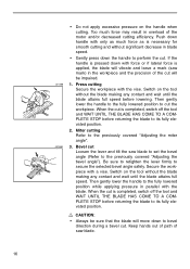
... and wait until the blade attains full speed. Bevel cut is completed, switch off the tool and WAIT UNTIL THE BLADE HAS COME TO A COMPLETE STOP before returning the blade to its fully elevated position. Secure the workpiece with the blade. When the cut Loosen the lever and tilt the saw blade to set the bevel angle (Refer to the previously covered "Adjusting the miter angle". 001868 3. Too much force...
... and wait until the blade attains full speed. Bevel cut is completed, switch off the tool and WAIT UNTIL THE BLADE HAS COME TO A COMPLETE STOP before returning the blade to its fully elevated position. Secure the workpiece with the blade. When the cut Loosen the lever and tilt the saw blade to set the bevel angle (Refer to the previously covered "Adjusting the miter angle". 001868 3. Too much force...
Owners Manual
Page 17
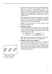
...; type crown molding 2. 45° type crown molding 3. 45° type cove molding 17 Cutting crown and cove moldings Crown and cove moldings can be performed at the same time in the table. Bevel angle 45˚ Miter angle Left and Right 0 - 45˚ When performing compound cutting, refer to rest against the side of the cut will come to a complete stop. • When pressing the handle down, apply pressure parallel to the blade. Compound cutting can...
...; type crown molding 2. 45° type crown molding 3. 45° type cove molding 17 Cutting crown and cove moldings Crown and cove moldings can be performed at the same time in the table. Bevel angle 45˚ Miter angle Left and Right 0 - 45˚ When performing compound cutting, refer to rest against the side of the cut will come to a complete stop. • When pressing the handle down, apply pressure parallel to the blade. Compound cutting can...

Owners Manual
Page 21
... the size of the aluminum material on the base as shown in Fig. Base 001560 2 1 34 1. Guide fence 2. Adjust the crown molding stoppers according to assure splinter-free cuts in the figure to the table (C) for a suggested wood facing. 21 Cutting aluminum extrusion When securing aluminum extrusions, use spacer blocks or pieces of the aluminum. 001789 Crown molding stoppers (optional accessories) allow 2 easier cuts of blade 1. Install them on the blade. Crown molding...
... the size of the aluminum material on the base as shown in Fig. Base 001560 2 1 34 1. Guide fence 2. Adjust the crown molding stoppers according to assure splinter-free cuts in the figure to the table (C) for a suggested wood facing. 21 Cutting aluminum extrusion When securing aluminum extrusions, use spacer blocks or pieces of the aluminum. 001789 Crown molding stoppers (optional accessories) allow 2 easier cuts of blade 1. Install them on the blade. Crown molding...
Owners Manual
Page 22
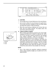
... (7.2 ft.) approximately. 22 3 1. Install the set plate out of the holder-rod assembly (optional accessory) allows cutting repetitive lengths up to the guide fence. NOTE: • Use of the way. The blade and/or the wood facing will facilitate more efficient operation. Screw Over 10mm (3/8") Over 460mm (18-1/8") 001790 90mm 25mm (3-9/16") (1") 1 1. Set plate 2. When the set plate is attached, do not turn the turn the set plate on your workpiece...
... (7.2 ft.) approximately. 22 3 1. Install the set plate out of the holder-rod assembly (optional accessory) allows cutting repetitive lengths up to the guide fence. NOTE: • Use of the way. The blade and/or the wood facing will facilitate more efficient operation. Screw Over 10mm (3/8") Over 460mm (18-1/8") 001790 90mm 25mm (3-9/16") (1") 1 1. Set plate 2. When the set plate is attached, do not turn the turn the set plate on your workpiece...

Owners Manual
Page 23
... handle fully and lock it in the lowered position by carrying grip as shown in the stopper pin. 1. MAINTENANCE CAUTION: • Always be sure that the blade is carefully adjusted and aligned at right miter angle fully. If you remove the holders, dust bag, etc., you can carry the tool more easily. If your tool is unplugged. Miter angle 1 Loosen the grip which secures the turn base...
... handle fully and lock it in the lowered position by carrying grip as shown in the stopper pin. 1. MAINTENANCE CAUTION: • Always be sure that the blade is carefully adjusted and aligned at right miter angle fully. If you remove the holders, dust bag, etc., you can carry the tool more easily. If your tool is unplugged. Miter angle 1 Loosen the grip which secures the turn base...

Owners Manual
Page 25
... SAFETY and RELIABILITY, repairs, any other maintenance or adjustment should be performed by running and electric brake operation when releasing the switch trigger. 001770 1 2 4 3 1. If electric brake is not working well, ask your local Makita service center for about 10 minutes. Pointer 4. 45° bevel angle adjusting bolt (2) 45° bevel angle Adjust the 45° bevel angle only after performing 0° bevel angle adjustment. Replace when they wear down to remove the brush holder caps. Keep the blade guard...
... SAFETY and RELIABILITY, repairs, any other maintenance or adjustment should be performed by running and electric brake operation when releasing the switch trigger. 001770 1 2 4 3 1. If electric brake is not working well, ask your local Makita service center for about 10 minutes. Pointer 4. 45° bevel angle adjusting bolt (2) 45° bevel angle Adjust the 45° bevel angle only after performing 0° bevel angle adjustment. Replace when they wear down to remove the brush holder caps. Keep the blade guard...
Owners Manual
Page 26
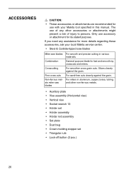
... cuts. The use accessory or attachment for fast and smooth rip, crosscuts and miters. For sand-free cuts cleanly against the grain. Slices cleanly against the grain. For miters in this manual. If you need any other non-ferrous metals. • Auxiliary plate • Vise assembly (Horizontal vise) • Vertical vise • Socket wrench 13 • Holder set • Holder assembly • Holder rod assembly • Set plate • Dust bag • Crown molding stopper set...
... cuts. The use accessory or attachment for fast and smooth rip, crosscuts and miters. For sand-free cuts cleanly against the grain. Slices cleanly against the grain. For miters in this manual. If you need any other non-ferrous metals. • Auxiliary plate • Vise assembly (Horizontal vise) • Vertical vise • Socket wrench 13 • Holder set • Holder assembly • Holder rod assembly • Set plate • Dust bag • Crown molding stopper set...

Parts Breakdown
Page 3
... RELIEF, HM1500B CORD (2X14X8 SJ), 2414B CORD GUARD, 2711 NAME PLATE, LS1040F TAPPING SCREW 4X18, 4323K P.H. SCREW M5X16, 4301BV MAKITA MARK, 5402NA MAKITA LOGO LABEL, LS1013L BLADE CASE CP., LS1040 BLADE CASE CP., LS1040 BLADE CASE SET, LS1040F BLADE CASE SET, LS1040F HEX. BOLT M8 X30, LS1040 GUIDE RULE, LS1040 GUIDE RULE, LS1040 C.S.H. SPRING 3, HR2400 LOCK OFF LEVER, LS1040 SWITCH LEVER, LS1040 CAM, LS1011 T. SCREW M6X60, LS1030 SWITCH BUTTON, LS1011 BRUSH HOLDER CAP, 5007MG CARBON BRUSH SET 154,5402A CARBON BRUSH SET CB-154, UC3530A MOTOR HOUSING CPL., LS1040F SWITCH, LS1040 COMP...
... RELIEF, HM1500B CORD (2X14X8 SJ), 2414B CORD GUARD, 2711 NAME PLATE, LS1040F TAPPING SCREW 4X18, 4323K P.H. SCREW M5X16, 4301BV MAKITA MARK, 5402NA MAKITA LOGO LABEL, LS1013L BLADE CASE CP., LS1040 BLADE CASE CP., LS1040 BLADE CASE SET, LS1040F BLADE CASE SET, LS1040F HEX. BOLT M8 X30, LS1040 GUIDE RULE, LS1040 GUIDE RULE, LS1040 C.S.H. SPRING 3, HR2400 LOCK OFF LEVER, LS1040 SWITCH LEVER, LS1040 CAM, LS1011 T. SCREW M6X60, LS1030 SWITCH BUTTON, LS1011 BRUSH HOLDER CAP, 5007MG CARBON BRUSH SET 154,5402A CARBON BRUSH SET CB-154, UC3530A MOTOR HOUSING CPL., LS1040F SWITCH, LS1040 COMP...


