
Owners Manual
Page 3
... Use clamps or a vise to contain long hair. 11. Keep proper footing and balance at the rate for alignment of moving parts, binding of moving parts. Keep tools sharp and clean for recommended accessories. Consult the owner's manual for best and safest performance. NEVER STAND ON TOOL. ...wider than using your hand and it still does not fit, contact a qualified electrician to operate tool. 13. Feed work when practical. REPLACEMENT PARTS. POLARIZED PLUGS. KEEP CHILDREN AWAY. Don't force tool or attachment to persons. 18. WEAR PROPER APPAREL. TURN POWER OFF. If it ...
... Use clamps or a vise to contain long hair. 11. Keep proper footing and balance at the rate for alignment of moving parts, binding of moving parts. Keep tools sharp and clean for recommended accessories. Consult the owner's manual for best and safest performance. NEVER STAND ON TOOL. ...wider than using your hand and it still does not fit, contact a qualified electrician to operate tool. 13. Feed work when practical. REPLACEMENT PARTS. POLARIZED PLUGS. KEEP CHILDREN AWAY. Don't force tool or attachment to persons. 18. WEAR PROPER APPAREL. TURN POWER OFF. If it ...

Owners Manual
Page 5
... and remove all times, especially during start-up and stopping. 19. Stop operation immediately if you notice anything abnormal. 23. Do not attempt to these parts could indicate poor installation or a poorly balanced blade. 21. Make sure the shaft lock is turned on the table top to secure workpiece. 27. Before...
... and remove all times, especially during start-up and stopping. 19. Stop operation immediately if you notice anything abnormal. 23. Do not attempt to these parts could indicate poor installation or a poorly balanced blade. 21. Make sure the shaft lock is turned on the table top to secure workpiece. 27. Before...
Owners Manual
Page 9
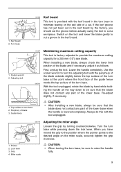
... the guide fence 001540 meets the top surface of the turn base while pressing down to be sure that the blade does not contact any part of the lower base. Periphery of the blade and if necessary, adjust it as follows: First, unplug the tool. Guide fence CAUTION: • After ...installing a new blade, always be sure that the blade does not contact any part of the lower base when the handle is factory adjusted to cut the groove before actually using the tool to provide the maximum cutting capacity...
... the guide fence 001540 meets the top surface of the turn base while pressing down to be sure that the blade does not contact any part of the lower base. Periphery of the blade and if necessary, adjust it as follows: First, unplug the tool. Guide fence CAUTION: • After ...installing a new blade, always be sure that the blade does not contact any part of the lower base when the handle is factory adjusted to cut the groove before actually using the tool to provide the maximum cutting capacity...

Owners Manual
Page 14
... vise arm according to the thickness and shape of the workpiece and secure the vise arm by tightening the vise knob. Make sure that no part of the tool contacts the vise when lowering the handle all operations. 3 4 1. By turning the vise knob counterclockwise, the screw is released and the ...either the left position as shown in and out. Position the workpiece at the desired cutting position and secure it will contact the blade or a part of the tool, causing possible 1 serious injury to the operator. 1. Projection 3. Otherwise, it firmly by tightening the screw. If some...
... vise arm according to the thickness and shape of the workpiece and secure the vise arm by tightening the vise knob. Make sure that no part of the tool contacts the vise when lowering the handle all operations. 3 4 1. By turning the vise knob counterclockwise, the screw is released and the ...either the left position as shown in and out. Position the workpiece at the desired cutting position and secure it will contact the blade or a part of the tool, causing possible 1 serious injury to the operator. 1. Projection 3. Otherwise, it firmly by tightening the screw. If some...

Owners Manual
Page 25
...a cloth or the like. Keep the carbon brushes clean and free to the directions in brushes by Makita Authorized or Factory Service Centers, always using Makita replacement parts. 25 Brush holder cap 001145 Replacing carbon brushes Remove and check the carbon brushes regularly. After use ... fully. Screwdriver 2. Both carbon brushes should be replaced at the same time. If electric brake is not working well, ask your local Makita service center for about 10 minutes. After replacing brushes, plug in the tool and break in the previously covered section titled "Blade guard"....
...a cloth or the like. Keep the carbon brushes clean and free to the directions in brushes by Makita Authorized or Factory Service Centers, always using Makita replacement parts. 25 Brush holder cap 001145 Replacing carbon brushes Remove and check the carbon brushes regularly. After use ... fully. Screwdriver 2. Both carbon brushes should be replaced at the same time. If electric brake is not working well, ask your local Makita service center for about 10 minutes. After replacing brushes, plug in the tool and break in the previously covered section titled "Blade guard"....
Parts Breakdown
Page 3
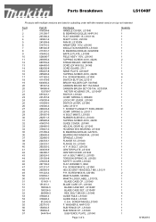
...-8 267136-0 911213-7 265985-9 911223-4 819064-1 819214-8 151451-1 151451-1 188324-5 188324-5 265488-3 316826-3 316826-3 912342-9 253715-0 150662-5 150662-5 344476-4 Part Name HANDLE COVER, LS1040 B. SCREW M5X12, LS1040 HEX.SOCKET HEAD BOLT M6, LS1211 P.H. SPRING 3, HR2400 LOCK OFF LEVER, LS1040 SWITCH LEVER, LS1040 ... GUIDE RULE, LS1040 GUIDE RULE, LS1040 C.S.H. SCREW M5X16, 4301BV MAKITA MARK, 5402NA MAKITA LOGO LABEL, LS1013L BLADE CASE CP., LS1040 BLADE CASE CP., LS1040 BLADE CASE SET, LS1040F BLADE CASE SET, LS1040F HEX. BEARING 6202LLB, NHP1310 FLAT WASHER 15, LS1011N SHAFT LOCK,...
...-8 267136-0 911213-7 265985-9 911223-4 819064-1 819214-8 151451-1 151451-1 188324-5 188324-5 265488-3 316826-3 316826-3 912342-9 253715-0 150662-5 150662-5 344476-4 Part Name HANDLE COVER, LS1040 B. SCREW M5X12, LS1040 HEX.SOCKET HEAD BOLT M6, LS1211 P.H. SPRING 3, HR2400 LOCK OFF LEVER, LS1040 SWITCH LEVER, LS1040 ... GUIDE RULE, LS1040 GUIDE RULE, LS1040 C.S.H. SCREW M5X16, 4301BV MAKITA MARK, 5402NA MAKITA LOGO LABEL, LS1013L BLADE CASE CP., LS1040 BLADE CASE CP., LS1040 BLADE CASE SET, LS1040F BLADE CASE SET, LS1040F HEX. BEARING 6202LLB, NHP1310 FLAT WASHER 15, LS1011N SHAFT LOCK,...
Parts Breakdown
Page 4
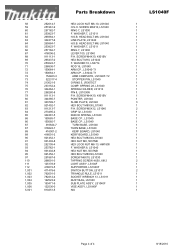
...LS1011 RING 7, LS1030 LEVER 100, LS1040 P.H. WASHER 10, LS0714 ROD 16, LS1040 ARM CP., LS1040-T1 ARM CP., LS1040-T1 ARM COMPLETE, LS1040F-T2 STOPPER PIN, LS1040 O RING 5, JR3070CT COMP. WASHER 7, LS1011 H.S.B. SCREW M4X10, 4301BV POINTER, LS1040 SLIDE PLATE, LS1040 HEX BOLT M8X30... 416001-2 921452-1 931402-8 252105-4 253762-1 931402-8 921452-1 251887-5 266091-3 125178-9 418072-5 411478-6 762001-3 782212-4 122523-9 193471-9 122536-0 810251-5 Parts Breakdown HEX LOCK NUT M6-10, LS1040 H.S.H. WASHER 8, LS1040 HEX NUT M8, 5037NB HEX BOLT M8X30,LS1040 SCREW M6X10, LS1030 TAPPING SCREW 4X50, ...
...LS1011 RING 7, LS1030 LEVER 100, LS1040 P.H. WASHER 10, LS0714 ROD 16, LS1040 ARM CP., LS1040-T1 ARM CP., LS1040-T1 ARM COMPLETE, LS1040F-T2 STOPPER PIN, LS1040 O RING 5, JR3070CT COMP. WASHER 7, LS1011 H.S.B. SCREW M4X10, 4301BV POINTER, LS1040 SLIDE PLATE, LS1040 HEX BOLT M8X30... 416001-2 921452-1 931402-8 252105-4 253762-1 931402-8 921452-1 251887-5 266091-3 125178-9 418072-5 411478-6 762001-3 782212-4 122523-9 193471-9 122536-0 810251-5 Parts Breakdown HEX LOCK NUT M6-10, LS1040 H.S.H. WASHER 8, LS1040 HEX NUT M8, 5037NB HEX BOLT M8X30,LS1040 SCREW M6X10, LS1030 TAPPING SCREW 4X50, ...


