Owners Manual
Page 2
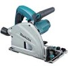
... an increased risk of flammable liquids, gases or dust. When operating a power tool outdoors, use an extension cord suitable for outdoor use the cord for the connection of electric shock. 8. Personal Safety 9. Use safety equipment. Remove any way. Do not overreach. Dress properly. cutting depth at 45° 40 mm (1-9/16") at 48° 38 mm (1-1/2") No load speed (RPM) 2,000 - 5,200/min Overall length 341 mm...
... an increased risk of flammable liquids, gases or dust. When operating a power tool outdoors, use an extension cord suitable for outdoor use the cord for the connection of electric shock. 8. Personal Safety 9. Use safety equipment. Remove any way. Do not overreach. Dress properly. cutting depth at 45° 40 mm (1-9/16") at 48° 38 mm (1-1/2") No load speed (RPM) 2,000 - 5,200/min Overall length 341 mm...
Owners Manual
Page 3
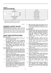
... changing accessories. 25. Use the power tool, accessories and tool bits etc. in your hands or across your second hand on and off . Use of arbour holes. Follow instruction for operations different from the blade below the workpiece. 4. Keep handles dry, clean and free from cutting area and the blade. Keep your leg. Do not attempt to minimize body exposure, blade binding, or loss of moving . CAUTION: Blades coast after turn...
... changing accessories. 25. Use the power tool, accessories and tool bits etc. in your hands or across your second hand on and off . Use of arbour holes. Follow instruction for operations different from the blade below the workpiece. 4. Keep handles dry, clean and free from cutting area and the blade. Keep your leg. Do not attempt to minimize body exposure, blade binding, or loss of moving . CAUTION: Blades coast after turn...
Owners Manual
Page 4
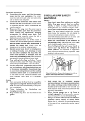
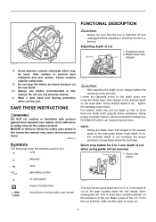
... a pinched, bound or misaligned saw blade, causing an uncontrolled saw and position your arms to a complete stop. 8. The blade washers and bolt were specially designed for optimum performance and safety of blade pinching and kickback. Never use gasoline. • Blade depth and bevel adjusting locking levers must be controlled by first removing it from the cut for any reason, release the trigger and hold the saw , for your body to...
... a pinched, bound or misaligned saw blade, causing an uncontrolled saw and position your arms to a complete stop. 8. The blade washers and bolt were specially designed for optimum performance and safety of blade pinching and kickback. Never use gasoline. • Blade depth and bevel adjusting locking levers must be controlled by first removing it from the cut for any reason, release the trigger and hold the saw , for your body to...

Owners Manual
Page 5
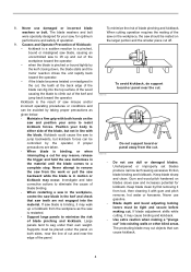
... the cut to maintain smooth advancement of cut " when the blade bevel setting is not at a speed so that the guide plate of the saw is accidentally dropped, guard may operate sluggishly due to damaged parts, gummy deposits, or a build-up of your hand, leading to stop after switch is short or small, clamp it takes for and remove all angles and depths of tool without slowing. 10. If saw will...
... the cut to maintain smooth advancement of cut " when the blade bevel setting is not at a speed so that the guide plate of the saw is accidentally dropped, guard may operate sluggishly due to damaged parts, gummy deposits, or a build-up of your hand, leading to stop after switch is short or small, clamp it takes for and remove all angles and depths of tool without slowing. 10. If saw will...
Owners Manual
Page 6
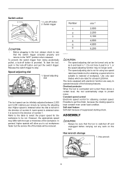
... This tool has the quick stop button for 2 to 3 mm depth of cut on the scale plate allows rough depth of usual cut . Quick stop button for 2 to 3 mm depth of cut . Make a pass of the 2 to the desired depth on the gear housing aside the rear handle when using guide rail (accessory) 1 1. Clamping screw 2. Take caution to the desired depth on the workpiece in this instruction manual may be sure that no load speed...
... This tool has the quick stop button for 2 to 3 mm depth of cut on the scale plate allows rough depth of usual cut . Quick stop button for 2 to 3 mm depth of cut . Make a pass of the 2 to the desired depth on the gear housing aside the rear handle when using guide rail (accessory) 1 1. Clamping screw 2. Take caution to the desired depth on the workpiece in this instruction manual may be sure that no load speed...

Owners Manual
Page 7
... base with the clamping screws. Tool base 1 007661 1 007657 Tilting to the right The tool can be tilted to 0° by itself. Positive stopper levers at the same time in the direction of arrow which has a marking -1. Bevel angle shifting lever Bevel cutting 1. To get 48° bevel angle, move the lever to 48° marking as far as it . Quick stop button toward the saw blade. Clamping screws 2. Sighting 1 2 1. Loosen the clamping screws...
... base with the clamping screws. Tool base 1 007661 1 007657 Tilting to the right The tool can be tilted to 0° by itself. Positive stopper levers at the same time in the direction of arrow which has a marking -1. Bevel angle shifting lever Bevel cutting 1. To get 48° bevel angle, move the lever to 48° marking as far as it . Quick stop button toward the saw blade. Clamping screws 2. Sighting 1 2 1. Loosen the clamping screws...
Owners Manual
Page 8
... prevent the switch trigger from being accidentally pulled, a lock-off button 2. To start because of suppressed starting shock. Release the switch trigger to operate because of number 6; lower speed is obtained when it past 6 or 1, or the speed adjusting function may differ with electronic function are rated for using low speed rated saw blades which is switched off button and pull the switch trigger. ASSEMBLY CAUTION: • Always be sure that the switch trigger actuates...
... prevent the switch trigger from being accidentally pulled, a lock-off button 2. To start because of suppressed starting shock. Release the switch trigger to operate because of number 6; lower speed is obtained when it past 6 or 1, or the speed adjusting function may differ with electronic function are rated for using low speed rated saw blades which is switched off button and pull the switch trigger. ASSEMBLY CAUTION: • Always be sure that the switch trigger actuates...
Owners Manual
Page 9
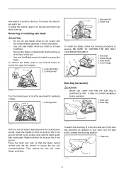
... remove hex wrench, just pull it will go. Removing or installing saw head for at least 5,200/min. • Be sure the blade is installed with teeth pointing up at the front of the tool. • Use only the Makita wrench to change the dust bag position. 1. Locking lever 2 1. Make sure that the lock pin fits in the groove formed by the locking lever and the depth guide with scale plate. To install hex wrench...
... remove hex wrench, just pull it will go. Removing or installing saw head for at least 5,200/min. • Be sure the blade is installed with teeth pointing up at the front of the tool. • Use only the Makita wrench to change the dust bag position. 1. Locking lever 2 1. Make sure that the lock pin fits in the groove formed by the locking lever and the depth guide with scale plate. To install hex wrench...
Owners Manual
Page 10
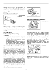
... it lightly to the cutting edge. If the cut and simply move the tool forward in the lock-off and unplug the tool. Turn two adjusting screws on the tool base so that the tool does not fall down the saw head slowly to the preset depth of the splinterguard corresponds to remove as possible. Dust port 1 2 007674 When using with a stroke. Remove the dust bag from saw , they cannot be cut by...
... it lightly to the cutting edge. If the cut and simply move the tool forward in the lock-off and unplug the tool. Turn two adjusting screws on the tool base so that the tool does not fall down the saw head slowly to the preset depth of the splinterguard corresponds to remove as possible. Dust port 1 2 007674 When using with a stroke. Remove the dust bag from saw , they cannot be cut by...

Owners Manual
Page 11
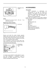
... following instructions. Adjusting screw for the tool. Use of the clamp (accessory) ensures firm hold of workpiece on the side of the blade guard show the absolute front and the absolute rear cutting points of the saw head slowly to the desired plunge position. Simply slide the rip fence up snugly against the side of tool base against a fixed stop or equivalent which is off, adjust the adjusting screws with a hex wrench while...
... following instructions. Adjusting screw for the tool. Use of the clamp (accessory) ensures firm hold of workpiece on the side of the blade guard show the absolute front and the absolute rear cutting points of the saw head slowly to the desired plunge position. Simply slide the rip fence up snugly against the side of tool base against a fixed stop or equivalent which is off, adjust the adjusting screws with a hex wrench while...
Owners Manual
Page 12
... product SAFETY and RELIABILITY, repairs, any other accessories or attachments might present a risk of 22.5° , 48° and -1° cut cannot be performed. Replace when they wear down to remove the brush holder caps. Only use with your local Makita Service Center. • Saw blades • Guide rail • Rip fence (Guide rule) • Miter gauge • Clamp • Hex wrench • Sheet set for guide rail • Rubber sheet set for guide rail • Position sheet set...
... product SAFETY and RELIABILITY, repairs, any other accessories or attachments might present a risk of 22.5° , 48° and -1° cut cannot be performed. Replace when they wear down to remove the brush holder caps. Only use with your local Makita Service Center. • Saw blades • Guide rail • Rip fence (Guide rule) • Miter gauge • Clamp • Hex wrench • Sheet set for guide rail • Rubber sheet set for guide rail • Position sheet set...
Owners Manual
Page 13
... OF THIS WARRANTY. This Warranty gives you specific legal rights, and you . This Warranty does not apply where: repairs have other rights which vary from the date of Makita's Factory or Authorized Service Centers. EN0006-1 13 Should any trouble develop during this one year period, return the COMPLETE tool, freight prepaid, to the tool. MAKITA LIMITED ONE YEAR WARRANTY Warranty Policy Every Makita tool is...
... OF THIS WARRANTY. This Warranty gives you specific legal rights, and you . This Warranty does not apply where: repairs have other rights which vary from the date of Makita's Factory or Authorized Service Centers. EN0006-1 13 Should any trouble develop during this one year period, return the COMPLETE tool, freight prepaid, to the tool. MAKITA LIMITED ONE YEAR WARRANTY Warranty Policy Every Makita tool is...

Parts Breakdown
Page 2
...-7 SPINDLE 1 26 285689-7 BEARING RETAINER 55 1 27 911221-8 PAN HEAD SCREW M5X16 2 28 419620-3 DUST NOZZLE 1 29 213460-9 O RING 35 1 029-1 213416-2 O RING 26 1 30 233479-2 COMPRESSION SPRING 11 1 31 419624-5 SPRING HOLDER 1 32 158095-8 LEVER 20 COMPLETE 1 32 263002-9 RUBBER PIN 4 1 33 213021-5 O RING 5 1 34 324710-8 PIN 8 1 35 266007-8 TAPPING SCREW BIND PT 3X10 1 36 253821-1 FLAT WASHER 3 1 37 419625-3 DEPTH GUIDE 1 38...
...-7 SPINDLE 1 26 285689-7 BEARING RETAINER 55 1 27 911221-8 PAN HEAD SCREW M5X16 2 28 419620-3 DUST NOZZLE 1 29 213460-9 O RING 35 1 029-1 213416-2 O RING 26 1 30 233479-2 COMPRESSION SPRING 11 1 31 419624-5 SPRING HOLDER 1 32 158095-8 LEVER 20 COMPLETE 1 32 263002-9 RUBBER PIN 4 1 33 213021-5 O RING 5 1 34 324710-8 PIN 8 1 35 266007-8 TAPPING SCREW BIND PT 3X10 1 36 253821-1 FLAT WASHER 3 1 37 419625-3 DEPTH GUIDE 1 38...

Parts Breakdown
Page 3
...-8 LOCK PLATE 1 88 687063-9 CORD CLAMP 1 89 265995-6 TAPPING SCREW 4X18 2 SOCKET HEAD BOLT M6 1 53 158214-6 BLADE CASE COVER COMPLETE 1 53 810303-2 CAUTION LABEL 1 54 266034-5 TAPPING SCREW CT 4X16 5 55 188197-6 HANDLE SET 1 55 INC. 102 0 56 265776-8 THUMB SCREW M6X26 1 57 253111-2 FLAT WASHER 6 1 58 419596-4 REAR ANGULAR GUIDE 1 059-1 318179-6 BASE 1 60 265995-6 TAPPING SCREW 4X18 2 61 324731-0 STOPPER PIN 1 62 252157-5 SQUARE NUT M6...
...-8 LOCK PLATE 1 88 687063-9 CORD CLAMP 1 89 265995-6 TAPPING SCREW 4X18 2 SOCKET HEAD BOLT M6 1 53 158214-6 BLADE CASE COVER COMPLETE 1 53 810303-2 CAUTION LABEL 1 54 266034-5 TAPPING SCREW CT 4X16 5 55 188197-6 HANDLE SET 1 55 INC. 102 0 56 265776-8 THUMB SCREW M6X26 1 57 253111-2 FLAT WASHER 6 1 58 419596-4 REAR ANGULAR GUIDE 1 059-1 318179-6 BASE 1 60 265995-6 TAPPING SCREW 4X18 2 61 324731-0 STOPPER PIN 1 62 252157-5 SQUARE NUT M6...

Parts Breakdown
Page 4
... CASE LABEL 1 90 631728-5 CONTROLLER 1 91 213261-5 O RING 17 1 92 418905-4 DIAL 1 94 419622-9 SWITCH LEVER 1 95 651922-3 SWITCH TG71B 1 96 345745-6 LINK PLATE 1 97 419629-5 LOCK OFF BUTTON 1 98 233089-5 COMPRESSION SPRING 12 1 99 265995-6 TAPPING SCREW 4X18 6 100 911273-9 PAN HEAD SCREW M5X50 1 101 862913-1 SP6000 NAME PLATE 1 102 188197-6 HANDLE SET 1 102 INC. 55 0 103 664265-4 POWER SUPPLY CORD AWG#16-2-2.5 1 104 682505-8 CORD GUARD...
... CASE LABEL 1 90 631728-5 CONTROLLER 1 91 213261-5 O RING 17 1 92 418905-4 DIAL 1 94 419622-9 SWITCH LEVER 1 95 651922-3 SWITCH TG71B 1 96 345745-6 LINK PLATE 1 97 419629-5 LOCK OFF BUTTON 1 98 233089-5 COMPRESSION SPRING 12 1 99 265995-6 TAPPING SCREW 4X18 6 100 911273-9 PAN HEAD SCREW M5X50 1 101 862913-1 SP6000 NAME PLATE 1 102 188197-6 HANDLE SET 1 102 INC. 55 0 103 664265-4 POWER SUPPLY CORD AWG#16-2-2.5 1 104 682505-8 CORD GUARD...

Flyer (English)
Page 1
...; Model SP6000K Release lever for Smooth Start-Ups Large Cutting Capacity (2-3/16" at 90º and 1-9/16" at 45º) CONVENIENCE Close-to-wall cutting; 6-1/2" PLUNGE CIRCULAR SAW PRECISION ACCURATE CUTTING DELIVERS A SPLINTER-FREE MIRROR FINISH Electronic Speed Control Maintains Constant Speed Under Load for Smooth Cutting Variable Speed Dial Control (2,000 - 5,200 RPM) for Optimum Performance in Current Limiter Helps Prevent Motor Burnout Powerful 12 AMP Motor for Continuous Operation...
...; Model SP6000K Release lever for Smooth Start-Ups Large Cutting Capacity (2-3/16" at 90º and 1-9/16" at 45º) CONVENIENCE Close-to-wall cutting; 6-1/2" PLUNGE CIRCULAR SAW PRECISION ACCURATE CUTTING DELIVERS A SPLINTER-FREE MIRROR FINISH Electronic Speed Control Maintains Constant Speed Under Load for Smooth Cutting Variable Speed Dial Control (2,000 - 5,200 RPM) for Optimum Performance in Current Limiter Helps Prevent Motor Burnout Powerful 12 AMP Motor for Continuous Operation...

Flyer (English)
Page 2
...-5) I Clamp Set (194385-5) Cam Adjustments I Saw base is attachable to other guide rail systems in the market STANDARD EQUIPMENT EASY BLADE CHANGES Locking lever holds the blade in depth stop allows a preliminary cut through the hole in the blade case for easier blade installation I Blade wrench attaches to the saw for fast and convenient blade changes I Electric brake for improved productivity I Built-in position to provide smooth perfect dead-on straight or bevel cutting I Tool-less cam adjustments...
...-5) I Clamp Set (194385-5) Cam Adjustments I Saw base is attachable to other guide rail systems in the market STANDARD EQUIPMENT EASY BLADE CHANGES Locking lever holds the blade in depth stop allows a preliminary cut through the hole in the blade case for easier blade installation I Blade wrench attaches to the saw for fast and convenient blade changes I Electric brake for improved productivity I Built-in position to provide smooth perfect dead-on straight or bevel cutting I Tool-less cam adjustments...


