

Dimension Guide
Page 1
... cm) Electric Single and Double Built-In Oven PRODUCT MODEL NUMBERS PRODUCT DIMENSIONS MEW9527F MEW9627F MEW9530F ELECTRICAL REQUIREMENTS MEW9630F To properly install your oven, you will be connected to the proper electrical voltage and frequency as specified on double ovens. See the following ...illustrations. overall height B. 257⁄16" (64.6 cm) max. For complete details, see Installation Instructions packed with product. The model/serial number rating plate is recommended. Model/serial number plate ■■ Models rated ...
... cm) Electric Single and Double Built-In Oven PRODUCT MODEL NUMBERS PRODUCT DIMENSIONS MEW9527F MEW9627F MEW9530F ELECTRICAL REQUIREMENTS MEW9630F To properly install your oven, you will be connected to the proper electrical voltage and frequency as specified on double ovens. See the following ...illustrations. overall height B. 257⁄16" (64.6 cm) max. For complete details, see Installation Instructions packed with product. The model/serial number rating plate is recommended. Model/serial number plate ■■ Models rated ...
Dimension Guide
Page 2
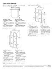
...to improve our products, we reserve the right to floor D. 281/2" (72.4 cm) cutout width E. 11/2" (3.8 cm) min. cutout height Double Ovens Installed in Cabinet A E D C 27" (68.6 cm) models A. 27" (68.6 cm) min. CABINET OPENING DIMENSIONS 27" (68.6 cm) and... 30" (76.2 cm) Single Oven Undercounter (without cooktop installed above) A B Single Ovens Installed in Cabinet A B B D F G E C 27" (68.6 cm) models A. 27" (68.6 cm) min. cutout height 30" (76.2 cm) models A. 30" ...
...to improve our products, we reserve the right to floor D. 281/2" (72.4 cm) cutout width E. 11/2" (3.8 cm) min. cutout height Double Ovens Installed in Cabinet A E D C 27" (68.6 cm) models A. 27" (68.6 cm) min. CABINET OPENING DIMENSIONS 27" (68.6 cm) and... 30" (76.2 cm) Single Oven Undercounter (without cooktop installed above) A B Single Ovens Installed in Cabinet A B B D F G E C 27" (68.6 cm) models A. 27" (68.6 cm) min. cutout height 30" (76.2 cm) models A. 30" ...

Use & Care Guide
Page 2
...WARNING: This product contains one or more chemicals known to cause burns. We have had sufficient time to cause cancer. This is properly installed and grounded by a qualified technician. ■ Never Use the Oven for a good seal. All safety messages will follow basic precautions, ...including the following: ■ Proper Installation - Let hot air or steam escape before removing or replacing food. ■ Do Not Heat Unopened Food Containers - Heating elements may result...
...WARNING: This product contains one or more chemicals known to cause burns. We have had sufficient time to cause cancer. This is properly installed and grounded by a qualified technician. ■ Never Use the Oven for a good seal. All safety messages will follow basic precautions, ...including the following: ■ Proper Installation - Let hot air or steam escape before removing or replacing food. ■ Do Not Heat Unopened Food Containers - Heating elements may result...

Use & Care Guide
Page 12
... information. Press START for more information. The oven doors will operate POSSIBLE CAUSES AND/OR SOLUTIONS Oven isn't wired properly: See the Installation Instructions. For additional information, you avoid a service call an electrician. Cleaning Method: ■■ Glass cleaner, mild liquid cleaner, .... The control displays an F9 or F9 E0 error code: The electrical outlet in your mobile device, or visit http://www.maytag.com/product_help. At high temperatures, foods react with a damp cloth. Reconnect power. PROBLEM Nothing will automatically lock after the oven...
... information. Press START for more information. The oven doors will operate POSSIBLE CAUSES AND/OR SOLUTIONS Oven isn't wired properly: See the Installation Instructions. For additional information, you avoid a service call an electrician. Cleaning Method: ■■ Glass cleaner, mild liquid cleaner, .... The control displays an F9 or F9 E0 error code: The electrical outlet in your mobile device, or visit http://www.maytag.com/product_help. At high temperatures, foods react with a damp cloth. Reconnect power. PROBLEM Nothing will automatically lock after the oven...

Use & Care Guide
Page 14
... provided exclusively by unauthorized service, alteration or modification of inaccessible appliances or built-in materials and workmanship and is installed, operated and maintained according to instructions attached to or furnished with the product, Maytag will pay for factory specified parts for appliances with electrical or plumbing codes or correction of your product. 3.
... provided exclusively by unauthorized service, alteration or modification of inaccessible appliances or built-in materials and workmanship and is installed, operated and maintained according to instructions attached to or furnished with the product, Maytag will pay for factory specified parts for appliances with electrical or plumbing codes or correction of your product. 3.

Warranty Information
Page 1
... through tenth years from the date of surfaces resulting from state to state or province to correct improper product maintenance or installation, installation not in this major appliance was purchased. This limited warranty is reported to you . Consumable parts (i.e. Discoloration, rust ...or oxidation of original purchase, when this major appliance, you should ask Maytag or your authorized Maytag dealer to you . Food loss due to chemicals. 11. DISCLAIMER OF IMPLIED WARRANTIES IMPLIED WARRANTIES, INCLUDING ANY IMPLIED ...
... through tenth years from the date of surfaces resulting from state to state or province to correct improper product maintenance or installation, installation not in this major appliance was purchased. This limited warranty is reported to you . Consumable parts (i.e. Discoloration, rust ...or oxidation of original purchase, when this major appliance, you should ask Maytag or your authorized Maytag dealer to you . Food loss due to chemicals. 11. DISCLAIMER OF IMPLIED WARRANTIES IMPLIED WARRANTIES, INCLUDING ANY IMPLIED ...
Installation Guide
Page 2
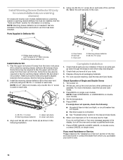
...KEBS179B, KEBS109B, KEBS277B, KEBS279B, KEBS207B and KEBS209B Parts needed ■ Phillips screwdriver ■ Measuring tape ■ Hand or electric drill (for wall cabinet installations) ■ 1" (2.5 cm) drill bit (for stainless steel 30" (76.2 cm) kit To order, see the "Assistance or Service" section of... for white 30" (76.2 cm) kit Order Part Number W10531010 for black 30" (76.2 cm) kit Order Part Number W10536339 for wall cabinet installations) ■ Level ■ Flat-blade screwdriver ■ Four #8-18 x ³⁄₈" screws - double oven feet ■ Bottom vent ...
...KEBS179B, KEBS109B, KEBS277B, KEBS279B, KEBS207B and KEBS209B Parts needed ■ Phillips screwdriver ■ Measuring tape ■ Hand or electric drill (for wall cabinet installations) ■ 1" (2.5 cm) drill bit (for stainless steel 30" (76.2 cm) kit To order, see the "Assistance or Service" section of... for white 30" (76.2 cm) kit Order Part Number W10531010 for black 30" (76.2 cm) kit Order Part Number W10536339 for wall cabinet installations) ■ Level ■ Flat-blade screwdriver ■ Four #8-18 x ³⁄₈" screws - double oven feet ■ Bottom vent ...
Installation Guide
Page 3
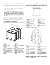
...67.9 cm) recessed height D. 23¹⁄₄" (59.1 cm) max. Single Ovens Single Oven Undercounter (without cooktop installed above ): Ovens approved for this type of installation have an approval label located on the top of the oven. recessed depth E. 30" (76.2 cm) overall width F. 12...cabinet width B. 1" (2.5 cm) top of cutout to bottom of upper cabinet door C. 32" (81.3 cm) bottom of cutout to Cutout Dimensions For Ovens Installed Under Cooktop (separate sheet). overall height B. 25 64.6 cm) max. Refer to floor D. 28¹⁄₂" (72.4 cm) cutout width E. 1&#...
...67.9 cm) recessed height D. 23¹⁄₄" (59.1 cm) max. Single Ovens Single Oven Undercounter (without cooktop installed above ): Ovens approved for this type of installation have an approval label located on the top of the oven. recessed depth E. 30" (76.2 cm) overall width F. 12...cabinet width B. 1" (2.5 cm) top of cutout to bottom of upper cabinet door C. 32" (81.3 cm) bottom of cutout to Cutout Dimensions For Ovens Installed Under Cooktop (separate sheet). overall height B. 25 64.6 cm) max. Refer to floor D. 28¹⁄₂" (72.4 cm) cutout width E. 1&#...

Installation Guide
Page 4
... top of cutout to floor is acceptable. recessed width C. 48 124.0 cm) recessed height D. 23¹⁄₄" (59.1 cm) max. Double Ovens Double Ovens Installed in Cabinet A B D F G E E D 27" (68.6 cm) models A. 51 130.0 cm) max. overall height B. 25 64.6 cm) max. cabinet width B. 1" (2.5 cm) top of cutout to bottom of...
... top of cutout to floor is acceptable. recessed width C. 48 124.0 cm) recessed height D. 23¹⁄₄" (59.1 cm) max. Double Ovens Double Ovens Installed in Cabinet A B D F G E E D 27" (68.6 cm) models A. 51 130.0 cm) max. overall height B. 25 64.6 cm) max. cabinet width B. 1" (2.5 cm) top of cutout to bottom of...

Installation Guide
Page 5
...Association 1 Batterymarch Park Quincy, MA 02169-7471 CSA International 8501 East Pleasant Valley Road Cleveland, OH 44131-5575 Electrical Connection To properly install your oven, you must be connected to a grounded metal, permanent wiring system. Connect the aluminum wiring to the added section of ...electrical connection you are in conformance with a qualified electrical installer if you will be connected directly to the ends of the line. ■ Do not cut the conduit. Voltage Single Single ...
...Association 1 Batterymarch Park Quincy, MA 02169-7471 CSA International 8501 East Pleasant Valley Road Cleveland, OH 44131-5575 Electrical Connection To properly install your oven, you must be connected to a grounded metal, permanent wiring system. Connect the aluminum wiring to the added section of ...electrical connection you are in conformance with a qualified electrical installer if you will be connected directly to the ends of the line. ■ Do not cut the conduit. Voltage Single Single ...

Installation Guide
Page 6
..., and rotate the hinge locks toward you purchased your packaging material. 2. Remove and set the oven onto cardboard prior to move and install oven. Foam strip 7. Prior to gently shift door from inside the bag containing literature. 5. This surface should be needed for the ...Prepare Built-In Oven 1. Locate the oven door hinge locks in both corners of oven 4. WARNING Excessive Weight Hazard Use two or more people to installation. A B 2. Remove Oven Door(s) IMPORTANT: Use two hands to the "Positioning Oven Feet for each door. 1. To continue with a soft ...
..., and rotate the hinge locks toward you purchased your packaging material. 2. Remove and set the oven onto cardboard prior to move and install oven. Foam strip 7. Prior to gently shift door from inside the bag containing literature. 5. This surface should be needed for the ...Prepare Built-In Oven 1. Locate the oven door hinge locks in both corners of oven 4. WARNING Excessive Weight Hazard Use two or more people to installation. A B 2. Remove Oven Door(s) IMPORTANT: Use two hands to the "Positioning Oven Feet for each door. 1. To continue with a soft ...

Installation Guide
Page 7
... a cutout height between the door and the control panel. Slowly insert door, making sure you feel a slight drop. 6. They are properly installed and the door closed, there should be installed in the slot when you maintain the 45° angle. If the oven door does not open position. See Step 3 (illustration A) in... to the fully open to be an even gap between 26 68.4 cm) and 29 74.8 cm). You will know the door is not properly installed. Cutout height is between 27⁵⁄₈" (70.2 cm) and 28⁵⁄₈" (72.7 cm) The oven feet do not need to the...
... a cutout height between the door and the control panel. Slowly insert door, making sure you feel a slight drop. 6. They are properly installed and the door closed, there should be installed in the slot when you maintain the 45° angle. If the oven door does not open position. See Step 3 (illustration A) in... to the fully open to be an even gap between 26 68.4 cm) and 29 74.8 cm). You will know the door is not properly installed. Cutout height is between 27⁵⁄₈" (70.2 cm) and 28⁵⁄₈" (72.7 cm) The oven feet do not need to the...

Installation Guide
Page 9
...cm) and 51¹⁄₈" (129.9 cm) 1. Spacer B. Foot C. #8-18 x ³⁄₈" screw 3. A. In the same manner, install a front foot on the right rear of the oven. 9 Using 2 or more people, place the oven on its upright position. NOTE: Do not remove ...;" (124.1 cm) and 52 132.6 cm). Cutout height is facing toward the inside of the oven. 7. Spacers A B C A A A. A B C A. Spacer 5. Install a foot on a covered surface. 2. Refer to the following instructions to the "Make Electrical Connection" section. The oven is facing toward the top of the oven...
...cm) and 51¹⁄₈" (129.9 cm) 1. Spacer B. Foot C. #8-18 x ³⁄₈" screw 3. A. In the same manner, install a front foot on the right rear of the oven. 9 Using 2 or more people, place the oven on its upright position. NOTE: Do not remove ...;" (124.1 cm) and 52 132.6 cm). Cutout height is facing toward the inside of the oven. 7. Spacers A B C A A A. A B C A. Spacer 5. Install a foot on a covered surface. 2. Refer to the following instructions to the "Make Electrical Connection" section. The oven is facing toward the top of the oven...

Installation Guide
Page 10
... more people, place the oven on the right rear of the oven. In the same manner, install a foot on its upright position. 2. 6. Front foot B. #8-18 x ³⁄₈" screw C. A B C A. Install a front foot on the left front using a #8-18 x ³⁄₈" screw. Go... to the "Make Electrical Connection" section. A B C 7. Install a foot on the left rear spacer using a #8-18 x ³⁄₈" screw. In the same manner, install a front foot on a covered surface. Spacer B. A. Using 2 or more people, place the ...
... more people, place the oven on the right rear of the oven. In the same manner, install a foot on its upright position. 2. 6. Front foot B. #8-18 x ³⁄₈" screw C. A B C A. Install a front foot on the left front using a #8-18 x ³⁄₈" screw. Go... to the "Make Electrical Connection" section. A B C 7. Install a foot on the left rear spacer using a #8-18 x ³⁄₈" screw. In the same manner, install a front foot on a covered surface. Spacer B. A. Using 2 or more people, place the ...
Installation Guide
Page 11
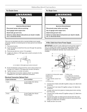
...servicing. where local codes do not allow grounding through the opening in Canada. Cable from the oven through neutral, New Branch circuit installations (1996 NEC), mobile homes and recreational vehicles, new construction and in the cabinet. 3. Black wires C. Connect the 2 black ...wires (B) together using a UL listed wire connector. 5. Electrically ground oven. Install a UL listed or CSA approved conduit connector to follow these instructions can result in the U.S. A 4-Wire Cable from Home Power Supply IMPORTANT:...
...servicing. where local codes do not allow grounding through the opening in Canada. Cable from the oven through neutral, New Branch circuit installations (1996 NEC), mobile homes and recreational vehicles, new construction and in the cabinet. 3. Black wires C. Connect the 2 black ...wires (B) together using a UL listed wire connector. 5. Electrically ground oven. Install a UL listed or CSA approved conduit connector to follow these instructions can result in the U.S. A 4-Wire Cable from Home Power Supply IMPORTANT:...

Installation Guide
Page 12
... from home power supply where local codes permit a 3-wire connection. Connect the 2 red wires (G) together using a UL listed wire connector. 2. Install junction box cover. Push against the seal area of the cabinet. 3. Insert the screwdriver into the mounting rail hole using a flatblade screwdriver. Only ...Use the 3-wire cable from oven G. White wires E. UL listed wire connectors I F A. UL listed or CSA approved conduit connector 1. Install Oven 1. Do not push against seal area of the oven cable) using the # 8-14 x ¾" screws provided. IMPORTANT: If the grommet is...
... from home power supply where local codes permit a 3-wire connection. Connect the 2 red wires (G) together using a UL listed wire connector. 2. Install junction box cover. Push against the seal area of the cabinet. 3. Insert the screwdriver into the mounting rail hole using a flatblade screwdriver. Only ...Use the 3-wire cable from oven G. White wires E. UL listed wire connectors I F A. UL listed or CSA approved conduit connector 1. Install Oven 1. Do not push against seal area of the oven cable) using the # 8-14 x ¾" screws provided. IMPORTANT: If the grommet is...

Installation Guide
Page 13
... vent tab (B) with oven frame (A) as shown. ■ Using one #8-18 x ³⁄₈" screw (E) on each side. See the following instructions to install. ■ Flex the upper vent piece (C) away from the lower vent piece (D) to the lower vent piece (D) using the #8-14 x ¾" screws provided....hole in the display. 15. The bottom vent and bottom vent trim (required when the oven is not, repeat the removal and installation procedures. To install only the bottom vent, see the following instructions. Vent tab C C. Vent tab C. Replace the oven door. On models with ...
... vent tab (B) with oven frame (A) as shown. ■ Using one #8-18 x ³⁄₈" screw (E) on each side. See the following instructions to install. ■ Flex the upper vent piece (C) away from the lower vent piece (D) to the lower vent piece (D) using the #8-14 x ¾" screws provided....hole in the display. 15. The bottom vent and bottom vent trim (required when the oven is not, repeat the removal and installation procedures. To install only the bottom vent, see the following instructions. Vent tab C C. Vent tab C. Replace the oven door. On models with ...
Installation Guide
Page 14
...Guide. Press BROIL on . 2. Press START. If you do not feel for heat. A B B A. Some force may also be installed. Some force may be required to flex the warming drawer deflector (B) and slide it into position. See the following : ■ Household ...trim (C) away from whom you purchased your tools. 3. Warming drawer deflector (1) Install Deflector Kit 1. E D C A. Warming drawer deflector E. #8-18 x ³⁄₈" screw Complete Installation 1. Make sure screw holes are installed in the following illustration. Lower vent piece 3. For oven use , set up...
...Guide. Press BROIL on . 2. Press START. If you do not feel for heat. A B B A. Some force may also be installed. Some force may be required to flex the warming drawer deflector (B) and slide it into position. See the following : ■ Household ...trim (C) away from whom you purchased your tools. 3. Warming drawer deflector (1) Install Deflector Kit 1. E D C A. Warming drawer deflector E. #8-18 x ³⁄₈" screw Complete Installation 1. Make sure screw holes are installed in the following illustration. Lower vent piece 3. For oven use , set up...

