
W10240504
Page 1
... damage of this data sheet. handle electronic control assembly by persons having electrical, electronic, and mechanical experience and knowledge at approximately 3000V. Contents Whirlpool, Maytag, and Kenmore Control Panels.... 2-4 Diagnostic Guide 5 Activating the Service Diagnostic Mode 5 Key Activation & Encoder Test 6 Service Test Mode 6 Service Test Mode Chart 7, 8 Software Version Display 9 Fault/Error Codes 9, 10 Troubleshooting Guide 11 Troubleshooting Tests 12-22 Strip Circuits 23 Wiring Diagrams 24, 25 Component Locations 26 DPAORNTONTOR. It takes...
... damage of this data sheet. handle electronic control assembly by persons having electrical, electronic, and mechanical experience and knowledge at approximately 3000V. Contents Whirlpool, Maytag, and Kenmore Control Panels.... 2-4 Diagnostic Guide 5 Activating the Service Diagnostic Mode 5 Key Activation & Encoder Test 6 Service Test Mode 6 Service Test Mode Chart 7, 8 Software Version Display 9 Fault/Error Codes 9, 10 Troubleshooting Guide 11 Troubleshooting Tests 12-22 Strip Circuits 23 Wiring Diagrams 24, 25 Component Locations 26 DPAORNTONTOR. It takes...

W10240504
Page 5
... dryer unplugged or power disconnected. IMPORTANT: Avoid using the same buttons (remember the buttons and the order that a time-delay fuse is power at the wall outlet. Has a household fuse blown or circuit breaker tripped? DO NOT REMOVE OR DESTROY PAGE 5 Activates Service Test Mode - Displays Next Error Code - You may damage the connectors upon insertion. Check all harnesses and connections before activation. Be sure the dryer is removed...
... dryer unplugged or power disconnected. IMPORTANT: Avoid using the same buttons (remember the buttons and the order that a time-delay fuse is power at the wall outlet. Has a household fuse blown or circuit breaker tripped? DO NOT REMOVE OR DESTROY PAGE 5 Activates Service Test Mode - Displays Next Error Code - You may damage the connectors upon insertion. Check all harnesses and connections before activation. Be sure the dryer is removed...

W10240504
Page 6
... user presses the POWER button or opens the door during Service Test Mode, the dryer exits to standby mode. PAGE 6 DO NOT REMOVE OR DESTROY Action: If console indicators begin flashing immediately. Review the Fault/Error Codes table on page 5. Rotating the cycle selector knob (on some models) turns off , "888" is displayed for 2 seconds, and the START button begins to activate the Service Diagnostic mode. FOR SERVICE TECHNICIAN'S USE ONLY...
... user presses the POWER button or opens the door during Service Test Mode, the dryer exits to standby mode. PAGE 6 DO NOT REMOVE OR DESTROY Action: If console indicators begin flashing immediately. Review the Fault/Error Codes table on page 5. Rotating the cycle selector knob (on some models) turns off , "888" is displayed for 2 seconds, and the START button begins to activate the Service Diagnostic mode. FOR SERVICE TECHNICIAN'S USE ONLY...

W10240504
Page 7
FOR SERVICE TECHNICIAN'S USE ONLY SERVICE TEST MODE CHART Step # Action Component User Interface Response 1 User enters Service Test Mode through Service Diagnostics. Check for Airflow begins automatically. If electric (Fuel = Electric): The UI will sound 3 times. 4 L1 voltage check completes. If START is pressed again or pressed and held before L1 voltage is available, a tone will report findings per the "Electric Dryer Results Display" section where L2...
FOR SERVICE TECHNICIAN'S USE ONLY SERVICE TEST MODE CHART Step # Action Component User Interface Response 1 User enters Service Test Mode through Service Diagnostics. Check for Airflow begins automatically. If electric (Fuel = Electric): The UI will sound 3 times. 4 L1 voltage check completes. If START is pressed again or pressed and held before L1 voltage is available, a tone will report findings per the "Electric Dryer Results Display" section where L2...

W10240504
Page 8
...Gas Dryer Results Display The frame rate will display it without illuminating the colon (range 0 to 200). Frame 3: Air Frame 4: See "Airflow Display Section". If electric (Fuel = Electric): The UI will show "---". If a "Detecting Airflow" LED is present, it also displays when the Status_Airflow = 2. 7 Service Loads Motor Off Test complete. Heater...FOR SERVICE TECHNICIAN'S USE ONLY SERVICE TEST MODE CHART (continued) Step # Action Component User Interface Response 6 Load Mass for Status_Airflow Heater On/Off is published to the UI. PAGE 8 DO NOT REMOVE OR...
...Gas Dryer Results Display The frame rate will display it without illuminating the colon (range 0 to 200). Frame 3: Air Frame 4: See "Airflow Display Section". If electric (Fuel = Electric): The UI will show "---". If a "Detecting Airflow" LED is present, it also displays when the Status_Airflow = 2. 7 Service Loads Motor Off Test complete. Heater...FOR SERVICE TECHNICIAN'S USE ONLY SERVICE TEST MODE CHART (continued) Step # Action Component User Interface Response 6 Load Mass for Status_Airflow Heater On/Off is published to the UI. PAGE 8 DO NOT REMOVE OR...

W10240504
Page 9
... fault code. used to clear the display. CODE DESCRIPTION PF Power Failure AF Restricted Airflow L2 Low Line Voltage CUSTOMER DIAGNOSTIC CODES EXPLANATION AND RECOMMENDED PROCEDURE PF indicates that airflow system is detected at the CCU. • Refer to Fault/Error Code "F4E4" for 5 seconds. Press START to continue the cycle, or press POWER to activate the Service Diagnostic mode for 5 seconds. Check lint screen, exhaust duct, exhaust...
... fault code. used to clear the display. CODE DESCRIPTION PF Power Failure AF Restricted Airflow L2 Low Line Voltage CUSTOMER DIAGNOSTIC CODES EXPLANATION AND RECOMMENDED PROCEDURE PF indicates that airflow system is detected at the CCU. • Refer to Fault/Error Code "F4E4" for 5 seconds. Press START to continue the cycle, or press POWER to activate the Service Diagnostic mode for 5 seconds. Check lint screen, exhaust duct, exhaust...

W10240504
Page 10
... dryer model displaying the fault/error code. See TEST #6: Buttons and Indicators, page 21. F3E1 Exhaust Thermistor Open/Shorted Indicates that the part numbers of the ACU and the User Interface are plugged into the power outlet. • Unplug dryer or disconnect power and check the relay connections on the ACU. • Gas Models Only: Unplug dryer or disconnect power and check the P14 connection on the ACU (harness loopback on electric has tripped. If the temperature...
... dryer model displaying the fault/error code. See TEST #6: Buttons and Indicators, page 21. F3E1 Exhaust Thermistor Open/Shorted Indicates that the part numbers of the ACU and the User Interface are plugged into the power outlet. • Unplug dryer or disconnect power and check the relay connections on the ACU. • Gas Models Only: Unplug dryer or disconnect power and check the P14 connection on the ACU (harness loopback on electric has tripped. If the temperature...

W10240504
Page 11
... SELECTIONS DRUM WILL NOT SPIN WILL NOT HEAT HEATS IN AIR CYCLE SHUTS OFF BEFORE CLOTHES ARE DRY POSSIBLE CAUSE CHECKS & TESTS No power to "Use and Care Guide". Perform Key Activation & Encoder Test. Drive Belt / Belt Switch problem. Heater relay shorted. DO NOT REMOVE OR DESTROY PAGE 11 Check connections and harness continuity between AC plug and dryer. See Test #1: ACU Power Check, page 12. Door not fully closed , then press and hold the START button. ACU problem. See Test #4a: Outlet (Exhaust) Thermistor, page 18. User...
... SELECTIONS DRUM WILL NOT SPIN WILL NOT HEAT HEATS IN AIR CYCLE SHUTS OFF BEFORE CLOTHES ARE DRY POSSIBLE CAUSE CHECKS & TESTS No power to "Use and Care Guide". Perform Key Activation & Encoder Test. Drive Belt / Belt Switch problem. Heater relay shorted. DO NOT REMOVE OR DESTROY PAGE 11 Check connections and harness continuity between AC plug and dryer. See Test #1: ACU Power Check, page 12. Door not fully closed , then press and hold the START button. ACU problem. See Test #4a: Outlet (Exhaust) Thermistor, page 18. User...

W10240504
Page 12
...-2 P8-1 BR DRUM LAMP P14-1 (ON SOME MODELS) Heater Relay #1 (Gas & Elect.) P9 L1 - MOISTURE SENSOR P13-2 RED MOISTURE SENSOR P13-1 BLK MOISTURE SENSOR P14 - Unplug dryer or disconnect power. Perform voltage check inside header P2 on ACU, between pins 1 & 3-DO NOT SHORT PINS TOGETHER. THERMISTORS OUTLET THERMISTOR NC NC P14-6 R/W OUTLET THERMISTOR P14-5 BLK MODEL RTN (GAS MODEL) P14-4 BLK MODEL (GAS MODEL) Motor Relay P13 Heater - FOR SERVICE TECHNICIAN'S USE ONLY TROUBLESHOOTING TESTS IMPORTANT: The...
...-2 P8-1 BR DRUM LAMP P14-1 (ON SOME MODELS) Heater Relay #1 (Gas & Elect.) P9 L1 - MOISTURE SENSOR P13-2 RED MOISTURE SENSOR P13-1 BLK MOISTURE SENSOR P14 - Unplug dryer or disconnect power. Perform voltage check inside header P2 on ACU, between pins 1 & 3-DO NOT SHORT PINS TOGETHER. THERMISTORS OUTLET THERMISTOR NC NC P14-6 R/W OUTLET THERMISTOR P14-5 BLK MODEL RTN (GAS MODEL) P14-4 BLK MODEL (GAS MODEL) Motor Relay P13 Heater - FOR SERVICE TECHNICIAN'S USE ONLY TROUBLESHOOTING TESTS IMPORTANT: The...
W10240504
Page 13
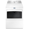
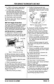
... step 5. If so, replace the main wire harness and test the dryer. 7. Perform steps under "Service Test Mode", page 6, to verify repair. If neither of the plug terminals have continuity with the left -most contact of the terminal block, replace the power cord and retest dryer. See figure 3. Visually check that ALL connectors are mechanically secure. Reassemble all parts and panels. 10. ELECTRIC DRYER (Canadian Installations): 1. DO NOT REMOVE OR DESTROY PAGE...
... step 5. If so, replace the main wire harness and test the dryer. 7. Perform steps under "Service Test Mode", page 6, to verify repair. If neither of the plug terminals have continuity with the left -most contact of the terminal block, replace the power cord and retest dryer. See figure 3. Visually check that ALL connectors are mechanically secure. Reassemble all parts and panels. 10. ELECTRIC DRYER (Canadian Installations): 1. DO NOT REMOVE OR DESTROY PAGE...
W10240504
Page 14
... power cord's L1 wire. If an open circuit is firmly connected to the back panel. P/N XXXXXX Rev X XXXX-XXX MADE IN COO Date Code YDDD-xx 5 N Neu COM 1 P8 Figure 4b - If it is necessary to step 6. Visually check that ALL connectors are fully inserted into the UI. Unplug dryer or disconnect power. 2. Test the continuity of the main harness from the rear panel...
... power cord's L1 wire. If an open circuit is firmly connected to the back panel. P/N XXXXXX Rev X XXXX-XXX MADE IN COO Date Code YDDD-xx 5 N Neu COM 1 P8 Figure 4b - If it is necessary to step 6. Visually check that ALL connectors are fully inserted into the UI. Unplug dryer or disconnect power. 2. Test the continuity of the main harness from the rear panel...
W10240504
Page 15
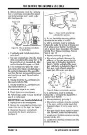
...motor Centrifugal switch Door switch Machine control electronics (See ESD information, page 1) Electric Dryer ü ü Gas Dryer ü ü Drum Belt Figure 7 - ALL DRYERS: Check the thermal fuse. Check the belt switch and drive motor. Remove the white connector from the spring-loaded belt switch pulley, gently letting the belt switch pulley down. See TEST #4b, page 19. Slowly remove drum belt. 5. Access the belt switch and drive motor by referring to remove console, top panel, toe panel, and front panel/ drum assembly). Perform steps under "Service Test...
...motor Centrifugal switch Door switch Machine control electronics (See ESD information, page 1) Electric Dryer ü ü Gas Dryer ü ü Drum Belt Figure 7 - ALL DRYERS: Check the thermal fuse. Check the belt switch and drive motor. Remove the white connector from the spring-loaded belt switch pulley, gently letting the belt switch pulley down. See TEST #4b, page 19. Slowly remove drum belt. 5. Access the belt switch and drive motor by referring to remove console, top panel, toe panel, and front panel/ drum assembly). Perform steps under "Service Test...
W10240504
Page 16
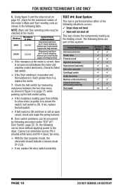
... the heating circuit. FOR SERVICE TECHNICIAN'S USE ONLY 6. Door switch problems can be done without applying power to a few ohms as shown in question and the resistance is OK. The following items are part of this system: Part of the following procedure under TEST #7: Door Switch, page 22. Check the belt switch by following situations occurs: 3 Dryer does not heat 3 Heat will not shut off High limit thermostat Heat element assembly Gas valve assembly Centrifugal switch Outlet thermistor Machine control...
... the heating circuit. FOR SERVICE TECHNICIAN'S USE ONLY 6. Door switch problems can be done without applying power to a few ohms as shown in question and the resistance is OK. The following items are part of this system: Part of the following procedure under TEST #7: Door Switch, page 22. Check the belt switch by following situations occurs: 3 Dryer does not heat 3 Heat will not shut off High limit thermostat Heat element assembly Gas valve assembly Centrifugal switch Outlet thermistor Machine control...

W10240504
Page 17
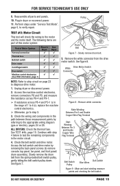
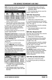
..., gas dryer, viewed from the red wire terminal at the thermal cut-off , and make sure that terminals are correctly inserted in the connectors and are functional. 1. High Limit Thermostat Assembly Thermal Cut-Off Heater Element Thermal Fuse Outlet Thermistor Electric Dryer Figure 10a - Check Thermal Cut-off if it is electrically open . 7. Check Heater-use an ohmmeter to measure the resistance between the heater and thermal cut -off -using figures 10a and 10b. Remove the toe panel to strip circuit...
..., gas dryer, viewed from the red wire terminal at the thermal cut-off , and make sure that terminals are correctly inserted in the connectors and are functional. 1. High Limit Thermostat Assembly Thermal Cut-Off Heater Element Thermal Fuse Outlet Thermistor Electric Dryer Figure 10a - Check Thermal Cut-off if it is electrically open . 7. Check Heater-use an ohmmeter to measure the resistance between the heater and thermal cut -off -using figures 10a and 10b. Remove the toe panel to strip circuit...
W10240504
Page 18
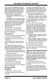
... the outlet temperature thermistor. PAGE 18 DO NOT REMOVE OR DESTROY Remove the toe panel to the dryer is activated. Reassemble all parts and panels. 9. Heat will not shut off to terminals 1 & 2 of the K2 relay at the connector. Refer to verify repair. The ACU monitors the exhaust temperature using the outlet thermistor, and cycles the heater relay on . 2. Plug in dryer or reconnect power. 10. Verify the gas supply to access thermal components. 4. Unplug dryer or disconnect power. 3. Locate...
... the outlet temperature thermistor. PAGE 18 DO NOT REMOVE OR DESTROY Remove the toe panel to the dryer is activated. Reassemble all parts and panels. 9. Heat will not shut off to terminals 1 & 2 of the K2 relay at the connector. Refer to verify repair. The ACU monitors the exhaust temperature using the outlet thermistor, and cycles the heater relay on . 2. Plug in dryer or reconnect power. 10. Verify the gas supply to access thermal components. 4. Unplug dryer or disconnect power. 3. Locate...
W10240504
Page 19
... heat element malfunction. Access the gas valve by removing the toe panel. The correct exhaust temperatures are good, check the exhaust temperature value at any or all of the exhaust outlet. Unplug dryer or disconnect power. 2. Plug in duration and select a temperature setting using the Timed Dry cycle. 1. For thermal cut -off location, see figure 10a or 10b, page 17. 3. In addition, check for blocked or improper exhaust system, and, on electric dryers, for location. 4. If no error code is displayed and the connections...
... heat element malfunction. Access the gas valve by removing the toe panel. The correct exhaust temperatures are good, check the exhaust temperature value at any or all of the exhaust outlet. Unplug dryer or disconnect power. 2. Plug in duration and select a temperature setting using the Timed Dry cycle. 1. For thermal cut -off location, see figure 10a or 10b, page 17. 3. In addition, check for blocked or improper exhaust system, and, on electric dryers, for location. 4. If no error code is displayed and the connections...

W10240504
Page 20
... automatic cycle stops too soon, or runs much longer than expected. NOTE: If ignitor does not come out and ignite, the flame sensor needs replacing. Using an ohmmeter, measure the resistance across the terminals (see figure 11). Remove harness plugs. if not, replace coils. 10. Perform steps under "Service Test Mode", page 6, to step 5. 5. NOTE: Dryer will shut down automatically after 2½ hours. Measuring gas valve resistance. 4. Part...
... automatic cycle stops too soon, or runs much longer than expected. NOTE: If ignitor does not come out and ignite, the flame sensor needs replacing. Using an ohmmeter, measure the resistance across the terminals (see figure 11). Remove harness plugs. if not, replace coils. 10. Perform steps under "Service Test Mode", page 6, to step 5. 5. NOTE: Dryer will shut down automatically after 2½ hours. Measuring gas valve resistance. 4. Part...

W10240504
Page 21
... START button in the 7-segment display. 3. The dryer will beep and the current dryness setting will be lengthened or shortened by changing the Customer-Focused Dryness Level from this mode does not start a drying cycle). Visually check that ALL ACU connectors are not present, replace the ACU. 6. If the moisture sensor diagnostic test passes, check the outlet thermistor: TEST #4a, page 18. If the problem persists after a power loss...
... START button in the 7-segment display. 3. The dryer will beep and the current dryness setting will be lengthened or shortened by changing the Customer-Focused Dryness Level from this mode does not start a drying cycle). Visually check that ALL ACU connectors are not present, replace the ACU. 6. If the moisture sensor diagnostic test passes, check the outlet thermistor: TEST #4a, page 18. If the problem persists after a power loss...

W10240504
Page 22
... (UI). 3. Unplug dryer or disconnect power. 3. Visually check that ALL UI connectors are inserted all parts and panels. 5. Unplug dryer or disconnect power. 2. Remove the console to access the machine electronics. 3. TEST #7: Door Switch Functionality is verified when opening the door turns on , replace the drum light bulb. If no voltage is securely connected to wiring diagrams on . Remove console to access ACU and user interface (UI). 3. Plug in dryer or reconnect power and press the POWER button. If...
... (UI). 3. Unplug dryer or disconnect power. 3. Visually check that ALL UI connectors are inserted all parts and panels. 5. Unplug dryer or disconnect power. 2. Remove the console to access the machine electronics. 3. TEST #7: Door Switch Functionality is verified when opening the door turns on , replace the drum light bulb. If no voltage is securely connected to wiring diagrams on . Remove console to access ACU and user interface (UI). 3. Plug in dryer or reconnect power and press the POWER button. If...

W10240504
Page 26
...) • User Interface (UI) Door Switch (Location may vary between models) • Drum Light Assembly • Thermal Cut-off • High Limit Thermostat • Heater Assembly • Motor Assembly • Thermal Fuse • Outlet Thermistor • Moisture Sensor Strips Figure 16 - Blue Black-White Red Blue-White (Electric) Blue (Gas) Green-Yellow Red-White Pluggable Drive Motor Switch PAGE 26 DO NOT REMOVE OR DESTROY Contacts Function 1M 2M 3M 5M 6M Start Run = Contacts...
...) • User Interface (UI) Door Switch (Location may vary between models) • Drum Light Assembly • Thermal Cut-off • High Limit Thermostat • Heater Assembly • Motor Assembly • Thermal Fuse • Outlet Thermistor • Moisture Sensor Strips Figure 16 - Blue Black-White Red Blue-White (Electric) Blue (Gas) Green-Yellow Red-White Pluggable Drive Motor Switch PAGE 26 DO NOT REMOVE OR DESTROY Contacts Function 1M 2M 3M 5M 6M Start Run = Contacts...


