
Instruction Manual
Page 2
... Sky Imager," "LX600," and "Tonight's Best" are trademarks registered with the U.S. Patent: US 6,392,799 and other Patents Pending. © 2013 Meade Instruments Corp. WARNING! Protected by U.S. Two or more persons should always be used whenever performing any of Meade Instruments Corp. Patent...serious injury or death. ® The name "Meade," "AutoStar,""StarLock" and the Meade logo are trademarks of the described tasks. Due to the weight and size of the 16" LX600ACF models, please use extreme caution whenever assembling, disassembling, lifting, transporting or storing this product....
... Sky Imager," "LX600," and "Tonight's Best" are trademarks registered with the U.S. Patent: US 6,392,799 and other Patents Pending. © 2013 Meade Instruments Corp. WARNING! Protected by U.S. Two or more persons should always be used whenever performing any of Meade Instruments Corp. Patent...serious injury or death. ® The name "Meade," "AutoStar,""StarLock" and the Meade logo are trademarks of the described tasks. Due to the weight and size of the 16" LX600ACF models, please use extreme caution whenever assembling, disassembling, lifting, transporting or storing this product....
Instruction Manual
Page 3
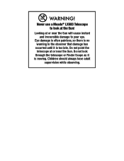
Eye damage is often painless, so there is no warning to the observer that damage has occurred until it is too late. Never use a Meade® LX600 Telescope to your eye. Do not point the telescope at or near the Sun will cause instant and irreversible damage to look through the telescope or Finder Scope as it is moving. Children should always have adult supervision while observing. Looking at the Sun! WARNING! Do not look at or near the Sun.
Eye damage is often painless, so there is no warning to the observer that damage has occurred until it is too late. Never use a Meade® LX600 Telescope to your eye. Do not point the telescope at or near the Sun will cause instant and irreversible damage to look through the telescope or Finder Scope as it is moving. Children should always have adult supervision while observing. Looking at the Sun! WARNING! Do not look at or near the Sun.
Instruction Manual
Page 4
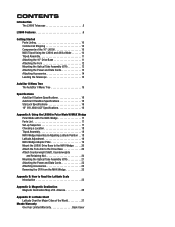
... 14 Leveling the Telescope 14 AutoStar II Menu Tree The AutoStar II Menu Tree 15 Specifications AutoStar II System Specifications 16 AutoStar II Handbox Specifications 16 StarLock Specifications 16 16" f/8 LX600 ACF Specifications 16 Appendix A: Using the LX600 in Polar Mode W/MAX Wedge Polar Mode with the MAX-Wedge 17 Parts List 17 Set-up Sequence 17 Choosing a Location 18 Tripod Assembly 18 MAX-Wedge Assembly & Adjusting Latitude Position...
... 14 Leveling the Telescope 14 AutoStar II Menu Tree The AutoStar II Menu Tree 15 Specifications AutoStar II System Specifications 16 AutoStar II Handbox Specifications 16 StarLock Specifications 16 16" f/8 LX600 ACF Specifications 16 Appendix A: Using the LX600 in Polar Mode W/MAX Wedge Polar Mode with the MAX-Wedge 17 Parts List 17 Set-up Sequence 17 Choosing a Location 18 Tripod Assembly 18 MAX-Wedge Assembly & Adjusting Latitude Position...
Instruction Manual
Page 5
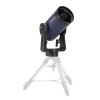
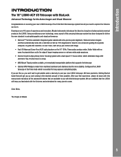
... are available to you up your new LX600 telescope! Introduction INTRODUCTION The 16" LX600-ACF f/8 Telescope with StarLock Advanced Technology for down with this manual and read about all you fascinated with the Universe and entertained for many years to come. We have provided a Getting Started Guide that supports the telescope. • Optional MAX-Wedge is essential for more stability...
... are available to you up your new LX600 telescope! Introduction INTRODUCTION The 16" LX600-ACF f/8 Telescope with StarLock Advanced Technology for down with this manual and read about all you fascinated with the Universe and entertained for many years to come. We have provided a Getting Started Guide that supports the telescope. • Optional MAX-Wedge is essential for more stability...
Instruction Manual
Page 6
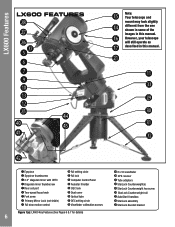
... lock 1% Dust cover 1^ Optical tube 1& DEC setting circle 1* Viewfinder collimation screws Figure 1(a): LX600 Key Features (See Pages 6 & 7 for details) 6 1( 8 x 50 viewfinder 2) GPS receiver 2! AutoStar L#4X96700HFAeNatDuBrOesX LX600 Features 2* 2& 2^ F3& G H J 1) 1# 1@ 2% 4$ 4) 4% 4! 1% Note: Your telescope and mount may look slightly 1$ different from the one shown in some of the 1^ images in this manual. Tube adapters 2@ StarLock Counterweight(s) 2# StarLock Counterweight...
... lock 1% Dust cover 1^ Optical tube 1& DEC setting circle 1* Viewfinder collimation screws Figure 1(a): LX600 Key Features (See Pages 6 & 7 for details) 6 1( 8 x 50 viewfinder 2) GPS receiver 2! AutoStar L#4X96700HFAeNatDuBrOesX LX600 Features 2* 2& 2^ F3& G H J 1) 1# 1@ 2% 4$ 4) 4% 4! 1% Note: Your telescope and mount may look slightly 1$ different from the one shown in some of the 1^ images in this manual. Tube adapters 2@ StarLock Counterweight(s) 2# StarLock Counterweight...

Instruction Manual
Page 8
...7, Fig. 1b, 1) and tighten in the Right Ascension, i.e. F. AutoStar L#4X96700HFAeNatDuBrOesX 16" LX600 features The Meade LX600 ACF models are extremely versatile, highperformance telescopes for imaging and visual use an add-on autoguider in conjunction with the optional Zero Image-Shift Microfocuser. E Diagonal... telescope assembly may result in the coarse focus and also to have planets orbiting about the horizontal axis. Note: See the instruction sheets that came with your autoguider for more information. 1# Tiltable AutoStar II Holder: Holds your LX600 ACF telescope using ...
...7, Fig. 1b, 1) and tighten in the Right Ascension, i.e. F. AutoStar L#4X96700HFAeNatDuBrOesX 16" LX600 features The Meade LX600 ACF models are extremely versatile, highperformance telescopes for imaging and visual use an add-on autoguider in conjunction with the optional Zero Image-Shift Microfocuser. E Diagonal... telescope assembly may result in the coarse focus and also to have planets orbiting about the horizontal axis. Note: See the instruction sheets that came with your autoguider for more information. 1# Tiltable AutoStar II Holder: Holds your LX600 ACF telescope using ...

Instruction Manual
Page 9
...4# 2" Extension Tube: If the micro-focuser is not used with updated Date, Time, and site information. 2! Note: The dust cover should be freely rotated by moving this weight. 2# StarLock Counterweight Hex Screws: Tighten to replacing the dust cover. 1^ Optical Tube: The main optical component... Declination (DEC) Setting Circle: Please refer to appendix E, Page 57, in the 10",12" & 14" LX600 manual that is further attached to the Dovetail Adapter Plate allowing connection to the Max-Wedge. 4% Dovetail Adapter Plate: Only used , the 2" extension tube connects the telescope rear cell to make...
...4# 2" Extension Tube: If the micro-focuser is not used with updated Date, Time, and site information. 2! Note: The dust cover should be freely rotated by moving this weight. 2# StarLock Counterweight Hex Screws: Tighten to replacing the dust cover. 1^ Optical Tube: The main optical component... Declination (DEC) Setting Circle: Please refer to appendix E, Page 57, in the 10",12" & 14" LX600 manual that is further attached to the Dovetail Adapter Plate allowing connection to the Max-Wedge. 4% Dovetail Adapter Plate: Only used , the 2" extension tube connects the telescope rear cell to make...

Instruction Manual
Page 10
...installed. Tripod lock lever lever Coarse adjustment lock lever Fig. 2: MAX-Tripod components. Using the 16" LX600 in Alt/Az mode The MAX mount tripod can safely carry the 16" LX600 massive payload in handling. With the addition of the components and an assembly fit easily into a Portable Pier... #G4et9t7inHgASNtDarBtOedX GETTING STARTED Parts Listing Getting the telescope ready for commercial shipment. n 16" LX600 ACF Optical Tube n Fork arms n Drive Base with adapter plate n MAX Field Tripod n StarLock unit with cable n Optional MAX Wedge Assembly The mount in the...
...installed. Tripod lock lever lever Coarse adjustment lock lever Fig. 2: MAX-Tripod components. Using the 16" LX600 in Alt/Az mode The MAX mount tripod can safely carry the 16" LX600 massive payload in handling. With the addition of the components and an assembly fit easily into a Portable Pier... #G4et9t7inHgASNtDarBtOedX GETTING STARTED Parts Listing Getting the telescope ready for commercial shipment. n 16" LX600 ACF Optical Tube n Fork arms n Drive Base with adapter plate n MAX Field Tripod n StarLock unit with cable n Optional MAX Wedge Assembly The mount in the...

Instruction Manual
Page 11
Set the top of the pentagon so it is pointing in place. The fully assembled telescope system is extremely heavy and it . See Figure 5 for shipping purposes and not used...Assembly Before you chose provides a clear view of the sky. CAUTION: Avoid grass and dirt. True North Fig. 3: Orient the tripod. Set ...assembled telescope can result in damage and may result in the telescope assembly procedure. Extend the legs outward. Verify that the top of the tripod (photo). Turn the three coarse adjustment leg lock levers to move it is coarsely level with the horizon. These bolts are used...
Set the top of the pentagon so it is pointing in place. The fully assembled telescope system is extremely heavy and it . See Figure 5 for shipping purposes and not used...Assembly Before you chose provides a clear view of the sky. CAUTION: Avoid grass and dirt. True North Fig. 3: Orient the tripod. Set ...assembled telescope can result in damage and may result in the telescope assembly procedure. Extend the legs outward. Verify that the top of the tripod (photo). Turn the three coarse adjustment leg lock levers to move it is coarsely level with the horizon. These bolts are used...
Instruction Manual
Page 13
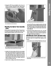
... that the bolts and holes are two shoulder bolts. Connect the DB-15 plug pre-installed in order to mount to 70 pounds each side and lift the OTA onto the top... Mounting the Optical Tube Assembly (OTA) This step requires two people who can lift up the telescope. Position the holes over the shoulder bolts. When they are in place using the provided hex key....plate. With you on the two top surfaces of the Dec. Fig. 15: Tighten the fork arm assembly using the four 3/8"-16 x 1 1/4" bolts and 3/8" washers. c. When they are in the DB-9 connectors to a firm...
... that the bolts and holes are two shoulder bolts. Connect the DB-15 plug pre-installed in order to mount to 70 pounds each side and lift the OTA onto the top... Mounting the Optical Tube Assembly (OTA) This step requires two people who can lift up the telescope. Position the holes over the shoulder bolts. When they are in place using the provided hex key....plate. With you on the two top surfaces of the Dec. Fig. 15: Tighten the fork arm assembly using the four 3/8"-16 x 1 1/4" bolts and 3/8" washers. c. When they are in the DB-9 connectors to a firm...

Instruction Manual
Page 14
... completely assembled the 16" LX600 telescope, and mounted all the accessories, it is in the OFF position. Fig. 17: Fine adjustment turnbuckle. 14 Fig. 18: Level Tripod. using the fine adjustment turnbuckles. casting (Fig. 16). Two short cords (8" long) with DB-9 connectors are supplied to provide power to the LX600 10", 12" and 14" manual for detailed mounting instructions...
... completely assembled the 16" LX600 telescope, and mounted all the accessories, it is in the OFF position. Fig. 17: Fine adjustment turnbuckle. 14 Fig. 18: Level Tripod. using the fine adjustment turnbuckles. casting (Fig. 16). Two short cords (8" long) with DB-9 connectors are supplied to provide power to the LX600 10", 12" and 14" manual for detailed mounting instructions...

Instruction Manual
Page 15
... Panel Light 12v Port Power Beep Battery Alarm Landmark Survey Select Item: Setup Align Easy One Star Two Star Align Home Drift Align Automatic Telescope Mount AltAz Polar Telescope Model Focal Length Max Slew Rate Mnt. Star Named Hipparcos Catalog SAO Catalog Etc...Set RA Rate Set DEC Rate Auto Rate Cal. DEC Guiding Reverse L/R Reverse Up/Down Home Sensors GPS Alignment On Off At Startup HPP Dome Delay RA PEC On/Off Erase Training Train Update DEC PEC On/Off Erase Training Train Update Field Derotater High Precision AutoStar II Menu Tree Lower Limit Park Position Use Current Use...
... Panel Light 12v Port Power Beep Battery Alarm Landmark Survey Select Item: Setup Align Easy One Star Two Star Align Home Drift Align Automatic Telescope Mount AltAz Polar Telescope Model Focal Length Max Slew Rate Mnt. Star Named Hipparcos Catalog SAO Catalog Etc...Set RA Rate Set DEC Rate Auto Rate Cal. DEC Guiding Reverse L/R Reverse Up/Down Home Sensors GPS Alignment On Off At Startup HPP Dome Delay RA PEC On/Off Erase Training Train Update DEC PEC On/Off Erase Training Train Update Field Derotater High Precision AutoStar II Menu Tree Lower Limit Park Position Use Current Use...

Instruction Manual
Page 16
... DVD 16-channel GPS receiver Net telescope weight 318 lbs. Faintest guide star 11th mag.) High-precision alignment Semi-automatic drift align procedure for ultra-precise polar alignment Weight 2.7 pounds 16" f/8 LX600 ACF Specifications Optical design Advanced Coma-Free Clear aperture 406.4mm (16") Focal length 3251mm Focal ratio (photographic speed f/8 Resolving power 0.29 arc sec Coatings Meade Ultra...
... DVD 16-channel GPS receiver Net telescope weight 318 lbs. Faintest guide star 11th mag.) High-precision alignment Semi-automatic drift align procedure for ultra-precise polar alignment Weight 2.7 pounds 16" f/8 LX600 ACF Specifications Optical design Advanced Coma-Free Clear aperture 406.4mm (16") Focal length 3251mm Focal ratio (photographic speed f/8 Resolving power 0.29 arc sec Coatings Meade Ultra...

Instruction Manual
Page 17
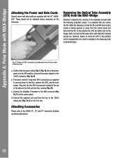
... allow the mount to the MAX-Wedge 4. Parts Listing The following parts are included with the MAX-Wedge MAX's Wedge assembly can be configured to cover three latitude ranges without the need of the steps involved when setting-up the MAX Tripod 2. Attach StarLock, StarLock...USING THE 16" LX600 IN POLAR MODE WITH MAX-WEDGE Polar Mode with the MAX-Wedge: • MAX-Wedge • Counterweight shaft • Counterweights (two) • Counterweight shaft safety cap • MAX-wedge dovetail adapter plate • MAX-wedge Addendum (assembly manual) • Hex keys and hardware Set...
... allow the mount to the MAX-Wedge 4. Parts Listing The following parts are included with the MAX-Wedge MAX's Wedge assembly can be configured to cover three latitude ranges without the need of the steps involved when setting-up the MAX Tripod 2. Attach StarLock, StarLock...USING THE 16" LX600 IN POLAR MODE WITH MAX-WEDGE Polar Mode with the MAX-Wedge: • MAX-Wedge • Counterweight shaft • Counterweights (two) • Counterweight shaft safety cap • MAX-wedge dovetail adapter plate • MAX-wedge Addendum (assembly manual) • Hex keys and hardware Set...

Instruction Manual
Page 18
...22: Lift and place the MAX-Wedge on to ± 5° of the telescope itself. Use the 3 three tripod lock levers on the tripod. The fully assembled telescope system is extremely heavy and it is best not to attempt to have been attached....Set the top of setting up your location. accessories have a clearance of collapsed tripod, note the raised pentagon pattern on the ground, a solid surface (such as a guide. level and tip over, causing serious injury to thoughtfully choose your 16" LX600 to the assembly and observers. MAX-Wedge Assembly and Adjusting Latitude Position Using...
...22: Lift and place the MAX-Wedge on to ± 5° of the telescope itself. Use the 3 three tripod lock levers on the tripod. The fully assembled telescope system is extremely heavy and it is best not to attempt to have been attached....Set the top of setting up your location. accessories have a clearance of collapsed tripod, note the raised pentagon pattern on the ground, a solid surface (such as a guide. level and tip over, causing serious injury to thoughtfully choose your 16" LX600 to the assembly and observers. MAX-Wedge Assembly and Adjusting Latitude Position Using...
Instruction Manual
Page 19
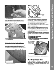
Replace and tighten the latitude bolts. Fine tune the latitude adjustment using three 1/2-13 x 5/8" socket cap screws. 19 Dovetail Adapter Plate Move and line up latitude tick mark with MAX-Wedge Fig. 24: Tripod lock levers. MAX-Wedge Adapter Plate In order to secure the 16" drive base...latitude locks screws. The wedge will need help reading the latitude scale. • Is your telescope pointing North? • Is your latitude tick mark with another set of the wedge (8 total) using a supplied hex Latitude Adjust Knob Fig. 27: MAX-Wedge latitude adjustment knob. Move the wedge...
Replace and tighten the latitude bolts. Fine tune the latitude adjustment using three 1/2-13 x 5/8" socket cap screws. 19 Dovetail Adapter Plate Move and line up latitude tick mark with MAX-Wedge Fig. 24: Tripod lock levers. MAX-Wedge Adapter Plate In order to secure the 16" drive base...latitude locks screws. The wedge will need help reading the latitude scale. • Is your telescope pointing North? • Is your latitude tick mark with another set of the wedge (8 total) using a supplied hex Latitude Adjust Knob Fig. 27: MAX-Wedge latitude adjustment knob. Move the wedge...

Instruction Manual
Page 20
...in the counterweight shaft into receiver and guide. Note the following: a. Once you have been threaded in the wedge receiver. The drive base adapter plate(Fig 1, 44) connects directly to the MAX-Wedge Using two people, firmly grasp the 16" LX600 Telescope Drive base, lift and place the ...wedge adapter dovetail in the drive base you can injure a foot if dropped on the drive base and secure using three 1/2-13 x 5/8" socket cap screws. Fig....
...in the counterweight shaft into receiver and guide. Note the following: a. Once you have been threaded in the wedge receiver. The drive base adapter plate(Fig 1, 44) connects directly to the MAX-Wedge Using two people, firmly grasp the 16" LX600 Telescope Drive base, lift and place the ...wedge adapter dovetail in the drive base you can injure a foot if dropped on the drive base and secure using three 1/2-13 x 5/8" socket cap screws. Fig....
Instruction Manual
Page 21
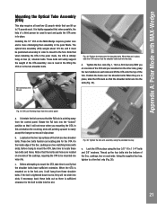
... a third person be used to spot and guide the OTA arms in order to mount to the fork. The optical tube assembly (OTA) weighs about ...OTA is sufficient clearance for the OTA. Fig. 36: Tighten the fork arm assembly using the four 3/8"-16 x 1 1/4" bolts and 3/8" washers. Thread up to 70 pounds each. ...MAX-Wedge Mounting the Optical Tube Assembly (OTA) This step requires at least two (2) people which that when installing the OTA in the lifting ... down b. Note orientation of the OTA assembly; In this orientation the receiving slots will safely support the weight of the RA Lock Fig....
... a third person be used to spot and guide the OTA arms in order to mount to the fork. The optical tube assembly (OTA) weighs about ...OTA is sufficient clearance for the OTA. Fig. 36: Tighten the fork arm assembly using the four 3/8"-16 x 1 1/4" bolts and 3/8" washers. Thread up to 70 pounds each. ...MAX-Wedge Mounting the Optical Tube Assembly (OTA) This step requires at least two (2) people which that when installing the OTA in the lifting ... down b. Note orientation of the OTA assembly; In this orientation the receiving slots will safely support the weight of the RA Lock Fig....
Instruction Manual
Page 22
...telescope and/ or personal injury. Fig. 37: Plug in the OFF position. Confirm that the RA Lock/RA slow-motion control is basically the reverse of the fork and the Dec. Two short cords (8" long) with DB-9 connectors are supplied with the 16... will not fall away when with the following important caveat. It is essential that you unlock the RA, rotate the telescope so that the power switch (Pg. 7, Fig. 1b, A) on the control panel. casting (Fig. 37). ...F) on the power panel is in the DB-9 connectors to the LX600 10", 12" and 14" manual for detailed mounting instructions. 22
...telescope and/ or personal injury. Fig. 37: Plug in the OFF position. Confirm that the RA Lock/RA slow-motion control is basically the reverse of the fork and the Dec. Two short cords (8" long) with DB-9 connectors are supplied with the 16... will not fall away when with the following important caveat. It is essential that you unlock the RA, rotate the telescope so that the power switch (Pg. 7, Fig. 1b, A) on the control panel. casting (Fig. 37). ...F) on the power panel is in the DB-9 connectors to the LX600 10", 12" and 14" manual for detailed mounting instructions. 22
Instruction Manual
Page 23
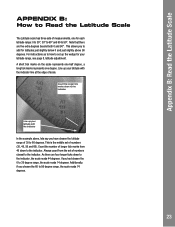
...indicator line at the edge of numbers closest to the indicator. This is the middle set of longer tick marks from the set up your latitude range, see page 8, latitude adjustment. For instructions as to how to set of scale. This allows you to add for latitudes just slightly below 0 and just..., the scale reads 74 degrees. 23 Appendix B: Read the Latitude Scale APPENDIX B: How to Read the Latitude Scale The Latitude scale has three sets of measurements, one degree. Note that there are four longer ticks down to 90°. As there are five extra degrees beyond both 0 and...
...indicator line at the edge of numbers closest to the indicator. This is the middle set of longer tick marks from the set up your latitude range, see page 8, latitude adjustment. For instructions as to how to set of scale. This allows you to add for latitudes just slightly below 0 and just..., the scale reads 74 degrees. 23 Appendix B: Read the Latitude Scale APPENDIX B: How to Read the Latitude Scale The Latitude scale has three sets of measurements, one degree. Note that there are four longer ticks down to 90°. As there are five extra degrees beyond both 0 and...


