
User Guide
Page 3
... by one or more of the FCC Rules. These limits are designed to Part 15 of the following measures: • Reorient or relocate the receiving antenna. • Increase the separation between the equipment and receiver. • Connect the equipment into an outlet on , the user is recommended to possible eye injury...
... by one or more of the FCC Rules. These limits are designed to Part 15 of the following measures: • Reorient or relocate the receiving antenna. • Increase the separation between the equipment and receiver. • Connect the equipment into an outlet on , the user is recommended to possible eye injury...

User Guide
Page 5
... try reversing the plug. Do not defeat the safety purpose of overhead power lines or other sources, refer to the product. POWER LINES An outside antenna system, extreme care should never be placed near a swimming pool. 8. Use a dry cloth for example: near a bathtub, washbowl, kitchen sink...not be moved with care. This product should be taken to read before cleaning. POWER SOURCES This product should be adhered to an outdoor antenna. 1. This is left unattended and unused for ventilation, to ensure reliable operation of power supply to overturn. 9. LIGHTNING To protect your...
... try reversing the plug. Do not defeat the safety purpose of overhead power lines or other sources, refer to the product. POWER LINES An outside antenna system, extreme care should never be placed near a swimming pool. 8. Use a dry cloth for example: near a bathtub, washbowl, kitchen sink...not be moved with care. This product should be taken to read before cleaning. POWER SOURCES This product should be adhered to an outdoor antenna. 1. This is left unattended and unused for ventilation, to ensure reliable operation of power supply to overturn. 9. LIGHTNING To protect your...
User Guide
Page 6
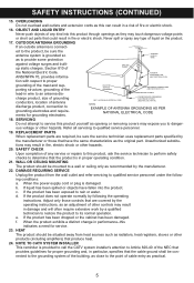
...or short out parts that the cable ground shall be situated away from the wall outlet and refer servicing to provide some protection ANTENNA LEAD IN WIRE against voltage surges and builtup static charges. c. SAFETY CHECK Upon completion of fire or electric shock. 16. nected... of cable entry as the original part. d. NATIONAL ELECTRICAL CODE POWER SERVICE GROUNDING ELECTRODE SYSTEM (NEC ART 250, PART H) S2898A EXAMPLE OF ANTENNA GROUNDING AS PER NATIONAL ELECTRICAL CODE 18. ing conditions: a. ed to the product, be mounted to a wall or ceiling only as radiators,...
...or short out parts that the cable ground shall be situated away from the wall outlet and refer servicing to provide some protection ANTENNA LEAD IN WIRE against voltage surges and builtup static charges. c. SAFETY CHECK Upon completion of fire or electric shock. 16. nected... of cable entry as the original part. d. NATIONAL ELECTRICAL CODE POWER SERVICE GROUNDING ELECTRODE SYSTEM (NEC ART 250, PART H) S2898A EXAMPLE OF ANTENNA GROUNDING AS PER NATIONAL ELECTRICAL CODE 18. ing conditions: a. ed to the product, be mounted to a wall or ceiling only as radiators,...

User Guide
Page 7
... Unit) 4. CLK SET (Clock Set) Button 7. Random Button 11. MEMORY/PROGRAM Button 18. PLAY/PAUSE (®p) Button 21. CD Compartment 6. PHONES (Headphones) Jack 14. FM Antenna 15. STOP (I) Button 20. LINE IN Jack 6 Bass Boost Button 8. LOCATION OF CONTROLS 1. Carrying Handle 2. AC Power Jack (Rear of Unit) 3. VOLUME Control 5. HR/Skip...
... Unit) 4. CLK SET (Clock Set) Button 7. Random Button 11. MEMORY/PROGRAM Button 18. PLAY/PAUSE (®p) Button 21. CD Compartment 6. PHONES (Headphones) Jack 14. FM Antenna 15. STOP (I) Button 20. LINE IN Jack 6 Bass Boost Button 8. LOCATION OF CONTROLS 1. Carrying Handle 2. AC Power Jack (Rear of Unit) 3. VOLUME Control 5. HR/Skip...
User Guide
Page 10
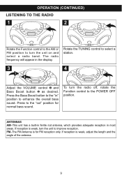
... in most areas. Press the Bass Boost button to the "in" position to the POWER OFF position. 1 ANTENNAS AM-This unit has a built-in ferrite rod antenna, which provides adequate reception in the display. Press to improve reception. Rotate the TUNING control to turn the unit... to the "out" position for FM reception only. FM-The FM Antenna is for normal bass sound. OPERATION (CONTINUED) LISTENING TO THE RADIO 1 2 Rotate the Function control to the AM or FM position to select a station. 3...
... in most areas. Press the Bass Boost button to the "in" position to the POWER OFF position. 1 ANTENNAS AM-This unit has a built-in ferrite rod antenna, which provides adequate reception in the display. Press to improve reception. Rotate the TUNING control to turn the unit... to the "out" position for FM reception only. FM-The FM Antenna is for normal bass sound. OPERATION (CONTINUED) LISTENING TO THE RADIO 1 2 Rotate the Function control to the AM or FM position to select a station. 3...

User Guide
Page 16
..., poor sound. Volume is set to minimum. Volume is set to the AM or FM position. Rotate the Function control to minimum. Reorient FM telescopic antenna. No sound. Defective disc. Clean or replace disc. Disc will not turn on disc. Station is not tuned properly. TROUBLESHOOTING GUIDE If you experience a problem...
..., poor sound. Volume is set to minimum. Volume is set to the AM or FM position. Rotate the Function control to minimum. Reorient FM telescopic antenna. No sound. Defective disc. Clean or replace disc. Disc will not turn on disc. Station is not tuned properly. TROUBLESHOOTING GUIDE If you experience a problem...


