
User Guide
Page 1
... important operating and maintenance (servicing) instructions in the literature accompanying the appliance. DANGEROUS VOLTAGE: The lightning flash with arrowhead symbol within an equilateral triangle is intended to alert the user to operate this equipment may generate or use radio frequency energy. and other countries... RISK OF ELECTRIC SHOCK, DO NOT REMOVE COVER (OR BACK). NO USERSERVICEABLE PARTS INSIDE. REFER SERVICING TO QUALIFIED SERVICE PERSONNEL. Changes or modifications to this equipment if an unauthorized change or modification is intended to alert the...
... important operating and maintenance (servicing) instructions in the literature accompanying the appliance. DANGEROUS VOLTAGE: The lightning flash with arrowhead symbol within an equilateral triangle is intended to alert the user to operate this equipment may generate or use radio frequency energy. and other countries... RISK OF ELECTRIC SHOCK, DO NOT REMOVE COVER (OR BACK). NO USERSERVICEABLE PARTS INSIDE. REFER SERVICING TO QUALIFIED SERVICE PERSONNEL. Changes or modifications to this equipment if an unauthorized change or modification is intended to alert the...

User Guide
Page 2
However, there is recommended to correct the interference by turning the equipment off and on, the user is encouraged to try to use a surge protector for AC connection. This equipment generates, uses and can be determined by one or more of the following measures: • ...: It is no guarantee that to which can radiate radio frequency energy and, if not installed and used in a particular installation. This Class B digital apparatus complies with Class B digital device regulations. If this product. Lightning and power surges ARE NOT covered under warranty for help. SAFETY ...
However, there is recommended to correct the interference by turning the equipment off and on, the user is encouraged to try to use a surge protector for AC connection. This equipment generates, uses and can be determined by one or more of the following measures: • ...: It is no guarantee that to which can radiate radio frequency energy and, if not installed and used in a particular installation. This Class B digital apparatus complies with Class B digital device regulations. If this product. Lightning and power surges ARE NOT covered under warranty for help. SAFETY ...

User Guide
Page 3
... or table recommended by the manufacturer. 8A. An appliance and cart combination should be connected to . 4. SAFETY PRECAUTIONS Before using the unit, be moved with care. READ INSTRUCTIONS All the safety and operating instructions should never be read all operating instructions carefully. WATER AND MOISTURE Do not use liquid cleaners or aerosol cleaners. Any mounting of power source...
... or table recommended by the manufacturer. 8A. An appliance and cart combination should be connected to . 4. SAFETY PRECAUTIONS Before using the unit, be moved with care. READ INSTRUCTIONS All the safety and operating instructions should never be read all operating instructions carefully. WATER AND MOISTURE Do not use liquid cleaners or aerosol cleaners. Any mounting of power source...
User Guide
Page 4
... in the vicinity of time, unplug it is connected to be located in a risk of any type of the polarized plug. 12. SAFETY PRECAUTIONS consult your electrician to the operating instructions. 11. OUTDOOR ANTENNA GROUNDING If an outside antenna system, extreme care should still fail to fit, contact your appliance dealer or local power company.
... in the vicinity of time, unplug it is connected to be located in a risk of any type of the polarized plug. 12. SAFETY PRECAUTIONS consult your electrician to the operating instructions. 11. OUTDOOR ANTENNA GROUNDING If an outside antenna system, extreme care should still fail to fit, contact your appliance dealer or local power company.

User Guide
Page 5
... those controls that are required, be sure the service technician uses replacement parts specified by the manufacturer. 22. The MAINS plug or an appliance coupler is damaged. WALL OR CEILING MOUNTING The product should be mounted to qualified service personnel under the following the operating instructions. e. SAFETY PRECAUTIONS protection against voltage surges and built-up static charges. SERVICING Do...
... those controls that are required, be sure the service technician uses replacement parts specified by the manufacturer. 22. The MAINS plug or an appliance coupler is damaged. WALL OR CEILING MOUNTING The product should be mounted to qualified service personnel under the following the operating instructions. e. SAFETY PRECAUTIONS protection against voltage surges and built-up static charges. SERVICING Do...

User Guide
Page 6
Display 4. PLAY/PAUSE Button 3 4. VOLUME + Button 4 5. Standby Indicator 3. FUNCTION Button 1 2 3. VOLUME - Button 5 6 FRONT LOCATION OF CONTROLS 1 1. STANDBY/ON Button 2. Remote Sensor RIGHT SIDE 234 1. iPod Dock 2.
Display 4. PLAY/PAUSE Button 3 4. VOLUME + Button 4 5. Standby Indicator 3. FUNCTION Button 1 2 3. VOLUME - Button 5 6 FRONT LOCATION OF CONTROLS 1 1. STANDBY/ON Button 2. Remote Sensor RIGHT SIDE 234 1. iPod Dock 2.
User Guide
Page 7
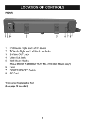
Fuse 7. TV Audio Right and Left Audio In Jacks 3. POWER ON/OFF Switch 8. Video Out Jack 5. REAR LOCATION OF CONTROLS 1 2 34 5 5 678 1. Wall Mount Hooks (WALL MOUNT ASSEMBLY PART NO. 2116i Wall Mount assy*) 6. S-Video OUT Jack 4. AC Cord *Consumer Replaceable Part (See page 18 to order.) 7 DVD Audio Right and Left In Jacks 2.
Fuse 7. TV Audio Right and Left Audio In Jacks 3. POWER ON/OFF Switch 8. Video Out Jack 5. REAR LOCATION OF CONTROLS 1 2 34 5 5 678 1. Wall Mount Hooks (WALL MOUNT ASSEMBLY PART NO. 2116i Wall Mount assy*) 6. S-Video OUT Jack 4. AC Cord *Consumer Replaceable Part (See page 18 to order.) 7 DVD Audio Right and Left In Jacks 2.

User Guide
Page 8
MODE button 4. Skip/Search o 10 Button (iPod) 5. MENU button 11 (iPod) 12 6. VOLUME - button 14 9. FUNCTION button 10. button 8. STANDBY/ON button 2. Skip/Search n Button (iPod) 12. BASS + Button 15. PLAY/PAUSE (®p) 15 Button (iPod) 11. VOLUME + Button REMOTE CONTROL PART NO. 21-1801-3916006LF* REMOTE BATTERY DOOR PART NO. 32-0111-3916202LF* *Consumer Replaceable Part (See page 18 to order.) 8 SELECT button (iPod) 13 7. MUTE button 9 3. BASS - Navigation DOWN Button (iPod) 14. LOCATION OF CONTROLS (CONTINUED) REMOTE 1 2 3 4 5 6 7 8 1....
MODE button 4. Skip/Search o 10 Button (iPod) 5. MENU button 11 (iPod) 12 6. VOLUME - button 14 9. FUNCTION button 10. button 8. STANDBY/ON button 2. Skip/Search n Button (iPod) 12. BASS + Button 15. PLAY/PAUSE (®p) 15 Button (iPod) 11. VOLUME + Button REMOTE CONTROL PART NO. 21-1801-3916006LF* REMOTE BATTERY DOOR PART NO. 32-0111-3916202LF* *Consumer Replaceable Part (See page 18 to order.) 8 SELECT button (iPod) 13 7. MUTE button 9 3. BASS - Navigation DOWN Button (iPod) 14. LOCATION OF CONTROLS (CONTINUED) REMOTE 1 2 3 4 5 6 7 8 1....
User Guide
Page 9
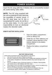
...batteries not intended to be used for a long period of electric shock. It is polarized to help minimize the possibility of time, remove the batteries to have an electrician replace the obsolete outlet. AC Plug AC Outlet AC Outlet AC Plug REMOTE BATTERY INSTALLATION 1. Replace the battery compartment cover. Reversed batteries... the device. 3. POWER SOURCE Insert the AC plug (with fresh ones. 4. they can overheat and rupture. (Follow battery manufacturer's directions.) 9 Open the battery compartment cover by sliding it off. 2. Install two (2) "AAA" batteries (not - + included...
...batteries not intended to be used for a long period of electric shock. It is polarized to help minimize the possibility of time, remove the batteries to have an electrician replace the obsolete outlet. AC Plug AC Outlet AC Outlet AC Plug REMOTE BATTERY INSTALLATION 1. Replace the battery compartment cover. Reversed batteries... the device. 3. POWER SOURCE Insert the AC plug (with fresh ones. 4. they can overheat and rupture. (Follow battery manufacturer's directions.) 9 Open the battery compartment cover by sliding it off. 2. Install two (2) "AAA" batteries (not - + included...
User Guide
Page 10
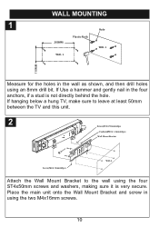
... 8mm drill bit. WALL MOUNTING 1 Hole 200MM Plastic Nails WAL L WAL L 110M M Measure for the holes in the wall as shown, and then drill holes using the two M4x16mm screws. 10 If hanging below a hung TV, make sure to leave at least 50mm between the TV and this unit. 2 Screw(ST4... x 50mm)x4pcs Cushion( 20 x 1.2mm)x4pcs Wall Mount Bracket Screw(M4 x 16mm)x2pcs WALL Attach the Wall Mount Bracket to the wall using the four ST4x50mm screws and washers, making sure it is not directly behind the hole. If Use a hammer and gently nail in the four anchors, if a stud is very secure.
... 8mm drill bit. WALL MOUNTING 1 Hole 200MM Plastic Nails WAL L WAL L 110M M Measure for the holes in the wall as shown, and then drill holes using the two M4x16mm screws. 10 If hanging below a hung TV, make sure to leave at least 50mm between the TV and this unit. 2 Screw(ST4... x 50mm)x4pcs Cushion( 20 x 1.2mm)x4pcs Wall Mount Bracket Screw(M4 x 16mm)x2pcs WALL Attach the Wall Mount Bracket to the wall using the four ST4x50mm screws and washers, making sure it is not directly behind the hole. If Use a hammer and gently nail in the four anchors, if a stud is very secure.

User Guide
Page 11
OR NOTES: • Set the TV's TV/VIDEO button or switch to the VIDEO setting. • When connecting the unit, refer to the owner's manual of the TV, as well as this manual. • When connecting the unit, make sure the power is off and both units are using an iPod that has photo/video capability, and your external TV. 11 OUTPUT CONNECTIONS If you are...
OR NOTES: • Set the TV's TV/VIDEO button or switch to the VIDEO setting. • When connecting the unit, refer to the owner's manual of the TV, as well as this manual. • When connecting the unit, make sure the power is off and both units are using an iPod that has photo/video capability, and your external TV. 11 OUTPUT CONNECTIONS If you are...
User Guide
Page 12
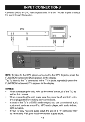
... button until DVD appears in the display. INPUT CONNECTIONS Connect a DVD to the DVD Audio In jacks and a TV to the TV Audio In jacks to output the sound through this manual. • When connecting the unit, make sure the power is off and both units are unplugged before making any connections. • Instead of the TV's or DVD's audio output, you can use...
... button until DVD appears in the display. INPUT CONNECTIONS Connect a DVD to the DVD Audio In jacks and a TV to the TV Audio In jacks to output the sound through this manual. • When connecting the unit, make sure the power is off and both units are unplugged before making any connections. • Instead of the TV's or DVD's audio output, you can use...
User Guide
Page 13
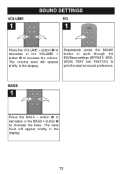
BASS 1 1 2 Press the BASS - The volume level will appear briefly in the display. The bass level will appear briefly in the display. 13 VOLUME 1 1 SOUND SETTINGS EQ 1 2 Press the VOLUME - button 1 to decrease or the VOLUME + button 2 to pick the desired sound preference. Repeatedly press the MODE button to cycle through the EQ/Bass settings (BYPASS, SRSWOW, TSXT and TSXT-DC) to increase the volume. button 1 to decrease or the BASS + button 2 to increase the bass.
BASS 1 1 2 Press the BASS - The volume level will appear briefly in the display. The bass level will appear briefly in the display. 13 VOLUME 1 1 SOUND SETTINGS EQ 1 2 Press the VOLUME - button 1 to decrease or the VOLUME + button 2 to pick the desired sound preference. Repeatedly press the MODE button to cycle through the EQ/Bass settings (BYPASS, SRSWOW, TSXT and TSXT-DC) to increase the volume. button 1 to decrease or the BASS + button 2 to increase the bass.
User Guide
Page 14
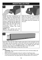
... is inserted into the Universal Dock (as shown. Slide the iPod into the dock, the iPod's battery will charge until it is turned off, once you connect the iPod, "iPod" will be in the Pause mode. • To remove the Universal Dock, insert your iPod (A) into the iPod compartment (B) (as shown), making sure the tabs are facing front, and slip the...
... is inserted into the Universal Dock (as shown. Slide the iPod into the dock, the iPod's battery will charge until it is turned off, once you connect the iPod, "iPod" will be in the Pause mode. • To remove the Universal Dock, insert your iPod (A) into the iPod compartment (B) (as shown), making sure the tabs are facing front, and slip the...

User Guide
Page 15
...the Skip/Search o 1 or n 2 button to select iPod mode; the Standby indicator will appear in the Standby mode, simply press the STANDBY/ON button on the remote; Repeatedly press the FUNCTION button to search within the currently-playing track. press once more to resume playback. ...1 2 To skip forward or backward on the iPod: Press the Skip/Search o 1 or n 2 button to skip to pause playback; You can operate the iPod using its own controls, as per its owner's manual, or you can use the controls on this unit on by pressing the POWER...
...the Skip/Search o 1 or n 2 button to select iPod mode; the Standby indicator will appear in the Standby mode, simply press the STANDBY/ON button on the remote; Repeatedly press the FUNCTION button to search within the currently-playing track. press once more to resume playback. ...1 2 To skip forward or backward on the iPod: Press the Skip/Search o 1 or n 2 button to skip to pause playback; You can operate the iPod using its own controls, as per its owner's manual, or you can use the controls on this unit on by pressing the POWER...

User Guide
Page 16
... menus. To turn the power off, press the STANDBY/ON button; See page 13 for details. the Standby indicator will light. 16 To navigate your selection. 7 3 8 4 5 1 2 Adjust the volume using the BASS - 4/+ 5 buttons. Set the EQ/BASS using the MODE button 3 and the BASS using the VOLUME - 1/+ 2 buttons. OPERATION (CONTINUED) 5 6 1 3 2 To navigate your iPod menus: At any time, press the MENU button to go back...
... menus. To turn the power off, press the STANDBY/ON button; See page 13 for details. the Standby indicator will light. 16 To navigate your selection. 7 3 8 4 5 1 2 Adjust the volume using the BASS - 4/+ 5 buttons. Set the EQ/BASS using the MODE button 3 and the BASS using the VOLUME - 1/+ 2 buttons. OPERATION (CONTINUED) 5 6 1 3 2 To navigate your iPod menus: At any time, press the MENU button to go back...

User Guide
Page 17
... volume using VOL + / - buttons. No image/video on your iPod, set to ON. In the Settings menu of your external TV. Check the connection (see page 11). Check the connection (see page 12). SYMPTOM No sound from iPod. Unit not connected with the AC cord and turned on . TROUBLESHOOTING GUIDE If you experience a problem with this unit, check the chart below before calling for service. CAUSE Volume...
... volume using VOL + / - buttons. No image/video on your iPod, set to ON. In the Settings menu of your external TV. Check the connection (see page 11). Check the connection (see page 12). SYMPTOM No sound from iPod. Unit not connected with the AC cord and turned on . TROUBLESHOOTING GUIDE If you experience a problem with this unit, check the chart below before calling for service. CAUSE Volume...

User Guide
Page 18
FOR ADDITIONAL SET-UP OR OPERATING ASSISTANCE, PLEASE VISIT OUR WEBSITE AT: WWW.MEMOREXELECTRONICS.COM OR CONTACT CUSTOMER SERVICE: For customers calling within Mexico, call 1-800-919-3647. PLEASE KEEP ALL PACKAGING ...developer to change without notice. FOR CONSUMER REPLACEABLE PART(S), SEE PART NUMBER(S) ON PAGES 7 AND 8 AND THEN CONTACT FOX INTERNATIONAL AT 1-800-321-6993. 18 SPECIFICATIONS Power source AC 120V/60Hz Power consumption 120W Subwoofer impedance 8 Ohm Surround impedance 8 Ohm S/N 60dB Subwoofer power output 50W Left and Right speakers power output 15Wx2 THD...
FOR ADDITIONAL SET-UP OR OPERATING ASSISTANCE, PLEASE VISIT OUR WEBSITE AT: WWW.MEMOREXELECTRONICS.COM OR CONTACT CUSTOMER SERVICE: For customers calling within Mexico, call 1-800-919-3647. PLEASE KEEP ALL PACKAGING ...developer to change without notice. FOR CONSUMER REPLACEABLE PART(S), SEE PART NUMBER(S) ON PAGES 7 AND 8 AND THEN CONTACT FOX INTERNATIONAL AT 1-800-321-6993. 18 SPECIFICATIONS Power source AC 120V/60Hz Power consumption 120W Subwoofer impedance 8 Ohm Surround impedance 8 Ohm S/N 60dB Subwoofer power output 50W Left and Right speakers power output 15Wx2 THD...
Service Manual
Page 1
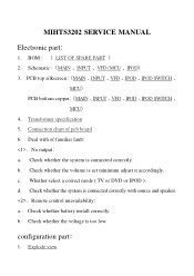
... a MCUĎ 4ē Transformer specification 5ē Connection chart of pcb board 6ē Deal with source and speaker. ēRemote control unavailabilityğ aē Check whether battery install correctly. configuration partğ 1ē Explode view bē Check whether the voltage is connected correctly. dē Check whether the system is set minimum adjust it accordingly. cē Whether select a correct mode ( TV or DVD or IPOD...
... a MCUĎ 4ē Transformer specification 5ē Connection chart of pcb board 6ē Deal with source and speaker. ēRemote control unavailabilityğ aē Check whether battery install correctly. configuration partğ 1ē Explode view bē Check whether the voltage is connected correctly. dē Check whether the system is set minimum adjust it accordingly. cē Whether select a correct mode ( TV or DVD or IPOD...

Service Manual
Page 28
1 2 3 SPEAKER BASS OUT D BASS OUT L OUT CON2 1 2 CON10 1 2 3 4 R OUT C CON9 1 2 3 CON8 MAIN CON12 CON6 CON7 4 CON11 CON1 6 5 4 3 2 1 CON3 3 2 1 6 5 4 3 2 1 5 4 3 2 1 2 1 1 2 5 4 3 2 1 B 5 6 CON401 1 D 2 3 INPUT 4 5 ... 9 8 7 6 5 4 3 2 1 1 2 3 4 5 1 2 1 2 10 11 1 2 3 4 5 3 2 1 1 2 3 4 5 6 7 8 9 TO-CON9 TO-CON8 TO-CON12 A TRANSFORMER 1 2 CON200 VFD 3 CON300 MCU 4 CON1 IPOD A Title TE-2116I connection chart of pcb board Size Number Revision B G.R.Q Date: File: 3-Jun-2008 E ddb Sheet of Drawn By: 5 6
1 2 3 SPEAKER BASS OUT D BASS OUT L OUT CON2 1 2 CON10 1 2 3 4 R OUT C CON9 1 2 3 CON8 MAIN CON12 CON6 CON7 4 CON11 CON1 6 5 4 3 2 1 CON3 3 2 1 6 5 4 3 2 1 5 4 3 2 1 2 1 1 2 5 4 3 2 1 B 5 6 CON401 1 D 2 3 INPUT 4 5 ... 9 8 7 6 5 4 3 2 1 1 2 3 4 5 1 2 1 2 10 11 1 2 3 4 5 3 2 1 1 2 3 4 5 6 7 8 9 TO-CON9 TO-CON8 TO-CON12 A TRANSFORMER 1 2 CON200 VFD 3 CON300 MCU 4 CON1 IPOD A Title TE-2116I connection chart of pcb board Size Number Revision B G.R.Q Date: File: 3-Jun-2008 E ddb Sheet of Drawn By: 5 6


