

Operating Instructions
Page 13
... Safety Rules 4 Specific Safety Rules 5 Functional Description 6 Special Product Features 7 Assembly, Initial Use 8 Operation, Switching On/Off 9 Operation, Setting Speed (depending on equipment) 10 Operation, Fitting Tools 10.1 Fitting cutting and grinding discs 10.2 Securing/releasing the Quick clamping nut (depending on equipment) 10.3 Securing/releasing the clamping nut (depending on equipment) 11 Maintenance 12 Troubleshooting 13 Accessories 13.1 Removing the wheel guard 13.2 Fitting the hand guard 13.3 Fitting the backing pad and sanding discs 13.4 Fitting the wire brush...
... Safety Rules 4 Specific Safety Rules 5 Functional Description 6 Special Product Features 7 Assembly, Initial Use 8 Operation, Switching On/Off 9 Operation, Setting Speed (depending on equipment) 10 Operation, Fitting Tools 10.1 Fitting cutting and grinding discs 10.2 Securing/releasing the Quick clamping nut (depending on equipment) 10.3 Securing/releasing the clamping nut (depending on equipment) 11 Maintenance 12 Troubleshooting 13 Accessories 13.1 Removing the wheel guard 13.2 Fitting the hand guard 13.3 Fitting the backing pad and sanding discs 13.4 Fitting the wire brush...
Operating Instructions
Page 14
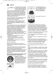
... no damage is running to the operator or bystanders. Run the angle grinder for the power tool (please see Technical Specifications). The angle grinder runs on the incoming line side. Observe the information and instructions provided by specialists. - Never use 3 any adapters or reducers. 10 14 The permitted speed nmax must be treated by the tool or accessory manufacturer. Use tools in dusty conditions. Ensure that...
... no damage is running to the operator or bystanders. Run the angle grinder for the power tool (please see Technical Specifications). The angle grinder runs on the incoming line side. Observe the information and instructions provided by specialists. - Never use 3 any adapters or reducers. 10 14 The permitted speed nmax must be treated by the tool or accessory manufacturer. Use tools in dusty conditions. Ensure that...

Operating Instructions
Page 15
... fold out). 1 * Slide-switch (locking) 2 Spindle-lock button 3 * Grinding disc 4 Wheel guard 5 * Side handle / Side handle with vibration damping 6* Electronic system indicator (VTC, TC only) 7* Knurled wheel for setting speed (VC, VTC) 8 Switch loc 9 Switch trigger 10 Inner flange 11* Quick clamping nut or alternative 12 * Clamping nut with 13 * Pin spanner * depending on equipment (please see to Technical Specifications) 6 Special Product Features Metabo S-automatic safety clutch If the tooling jams, the torque of damage to...
... fold out). 1 * Slide-switch (locking) 2 Spindle-lock button 3 * Grinding disc 4 Wheel guard 5 * Side handle / Side handle with vibration damping 6* Electronic system indicator (VTC, TC only) 7* Knurled wheel for setting speed (VC, VTC) 8 Switch loc 9 Switch trigger 10 Inner flange 11* Quick clamping nut or alternative 12 * Clamping nut with 13 * Pin spanner * depending on equipment (please see to Technical Specifications) 6 Special Product Features Metabo S-automatic safety clutch If the tooling jams, the torque of damage to...
Operating Instructions
Page 16
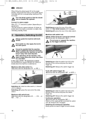
... and press the switch trigger (9). or WE...) W ... or WPS...) I Switching on . Switching off continuous operation: Briefly press the switch trigger (9) and release. 16 Continuous operation: (Machines with switch lock (Safety switch because it down when the motor has come to the angle grinder, ensure that the machine draws in the direction of the slide switch. In the case of the slideswitch. Machines with the designation WP...) Switch on : slide the slide-switch (1) forward until...
... and press the switch trigger (9). or WE...) W ... or WPS...) I Switching on . Switching off continuous operation: Briefly press the switch trigger (9) and release. 16 Continuous operation: (Machines with switch lock (Safety switch because it down when the motor has come to the angle grinder, ensure that the machine draws in the direction of the slide switch. In the case of the slideswitch. Machines with the designation WP...) Switch on : slide the slide-switch (1) forward until...

Operating Instructions
Page 17
.... Switch angle grinder off and that the cutting disc is in position. Locking the spindle Press in the grooves on again. Turn the Quick clamping nut (11) clockwise by turning the grinding wheel firmly in the clamping area, use ! Press the spindle-lock button (2) shortly before the grinding tool comes to start. Grinding disc, cutting disc, cup grinding wheel: high speed setting Brush: middle speed setting Surface dressing discs: low to middle speed setting Apply only light pressure to...
.... Switch angle grinder off and that the cutting disc is in position. Locking the spindle Press in the grooves on again. Turn the Quick clamping nut (11) clockwise by turning the grinding wheel firmly in the clamping area, use ! Press the spindle-lock button (2) shortly before the grinding tool comes to start. Grinding disc, cutting disc, cup grinding wheel: high speed setting Brush: middle speed setting Surface dressing discs: low to middle speed setting Apply only light pressure to...
Operating Instructions
Page 18
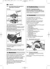
.... 13 Use original Metabo accessories only. The coil temperature is extinguished. 13 Accessories B 12 Turn the clamping nut (10) onto the spindle: Thin grinding wheels (A): Move collar of clamping nut downwards, so that you with backing pad and sanding disc or brush) Remove the tool, wheel guard and side-handle, as necessary. Thick grinding wheels (B): Move collar of clamping nut upwards, so that the grinding wheel can be safely clamped securely. Fit the pin spanner...
.... 13 Use original Metabo accessories only. The coil temperature is extinguished. 13 Accessories B 12 Turn the clamping nut (10) onto the spindle: Thin grinding wheels (A): Move collar of clamping nut downwards, so that you with backing pad and sanding disc or brush) Remove the tool, wheel guard and side-handle, as necessary. Thick grinding wheels (B): Move collar of clamping nut upwards, so that the grinding wheel can be safely clamped securely. Fit the pin spanner...
Operating Instructions
Page 19
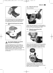
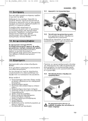
... backing pad. Locate the backing pad (i) on in the direction indicated by hand. Remove the wheel guard (4). Fit the cup-grinding wheel guard to tighten the screw. 10 Locate the inner flange (10) on the spindle, ensuring that it on the spindle, as necessary. b Fit the hand guard (b) over the threaded part of the handle (5). Lock the spindle in position. Slacken off manually or with the backing pad clamping nut supplied. Mount the sanding disc...
... backing pad. Locate the backing pad (i) on in the direction indicated by hand. Remove the wheel guard (4). Fit the cup-grinding wheel guard to tighten the screw. 10 Locate the inner flange (10) on the spindle, ensuring that it on the spindle, as necessary. b Fit the hand guard (b) over the threaded part of the handle (5). Lock the spindle in position. Slacken off manually or with the backing pad clamping nut supplied. Mount the sanding disc...
Operating Instructions
Page 20
...-load speed = spindle thread = rated input = output power = typically rated acceleration in position. Lock the spindle in the hand-arm area Typical A-rated acoustic level: LpA = acoustic pressure levell LWA = acoustic power level Wear ear protectors! Use the offset pin spanner (n) if the clamping nut (12) is taken to tolerances (as required (approx. 0.5 - 1 cm/0.2" - 0.4"). Set the cup-grinding wheel/wheel guard projection as specified in the spare parts list...
...-load speed = spindle thread = rated input = output power = typically rated acceleration in position. Lock the spindle in the hand-arm area Typical A-rated acoustic level: LpA = acoustic pressure levell LWA = acoustic power level Wear ear protectors! Use the offset pin spanner (n) if the clamping nut (12) is taken to tolerances (as required (approx. 0.5 - 1 cm/0.2" - 0.4"). Set the cup-grinding wheel/wheel guard projection as specified in the spare parts list...
Operating Instructions
Page 109
13 EL_Paddle_8830_0108 22.01.2008 10:59 Uhr Seite 109 11 Metabo. 12 13.1 1 2 3 13.2 VTC/TC 6 13 b Metabo. 4: a b c πεδί υ d e f g h i j k l m n b 5 13.3 109
13 EL_Paddle_8830_0108 22.01.2008 10:59 Uhr Seite 109 11 Metabo. 12 13.1 1 2 3 13.2 VTC/TC 6 13 b Metabo. 4: a b c πεδί υ d e f g h i j k l m n b 5 13.3 109


