Service Parts List
Page 1
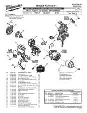
... Assembly (1) 34 14-29-0403 Gear Case Assembly (1) 35 10-20-3554 LED Label (not shown) (1) 36 42-55-0300 Zippered Tool Case (1) 60 49-16-3697 Bit Holder Kit (Accessory) (1) 61 06-82-3008 6-32 x 12.7mm Pan Hd. PART NO. REQ. 1 05-88-0202 Chuck Screw (1) 2 42-66-0400 1/2" (13mm) Keyless Chuck (1) 9 06-82-6351 M3 x 16mm Pan Hd. SCREW TORQUE SPECIFICATION CHART SEATING TORQUE FIG. PART...
... Assembly (1) 34 14-29-0403 Gear Case Assembly (1) 35 10-20-3554 LED Label (not shown) (1) 36 42-55-0300 Zippered Tool Case (1) 60 49-16-3697 Bit Holder Kit (Accessory) (1) 61 06-82-3008 6-32 x 12.7mm Pan Hd. PART NO. REQ. 1 05-88-0202 Chuck Screw (1) 2 42-66-0400 1/2" (13mm) Keyless Chuck (1) 9 06-82-6351 M3 x 16mm Pan Hd. SCREW TORQUE SPECIFICATION CHART SEATING TORQUE FIG. PART...
Service Parts List
Page 2
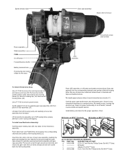
... illustrated above. Speed selector slide Gear case assembly Model 3403-20 shown Rotor assembly Stator assembly PCBA On-off switch Forward/reverse shuttle Battery terminal block Housing clip (not shown) slides into this point install two gear case screws (9), partially securing electronics assembly and gear case assembly. Remove left handle halve. Use a T-10 bit to wire routing and trapping. Insert the rotor pinion into the corresponding channels and cavities of gear case assembly, meshing the gears and seating the...
... illustrated above. Speed selector slide Gear case assembly Model 3403-20 shown Rotor assembly Stator assembly PCBA On-off switch Forward/reverse shuttle Battery terminal block Housing clip (not shown) slides into this point install two gear case screws (9), partially securing electronics assembly and gear case assembly. Remove left handle halve. Use a T-10 bit to wire routing and trapping. Insert the rotor pinion into the corresponding channels and cavities of gear case assembly, meshing the gears and seating the...