

External Control Codes
Page 5
... 15 minutes. Communication specification 3. And the controller (PC) has to re-connect to change, Please refer "Network settings" on User's manual. 7142 (Fixed) (Note) The monitor will disconnect the connection if no packet data is sent. TCP/IP (Internet protocol suite) Ethernet (CSMA/CD) Transport layer (TCP) * Using the payload of TCP segment. (Default) 192.168.0.10 * If you need to control the monitor again, after 15...
... 15 minutes. Communication specification 3. And the controller (PC) has to re-connect to change, Please refer "Network settings" on User's manual. 7142 (Fixed) (Note) The monitor will disconnect the connection if no packet data is sent. TCP/IP (Internet protocol suite) Ethernet (CSMA/CD) Transport layer (TCP) * Using the payload of TCP segment. (Default) 192.168.0.10 * If you need to control the monitor again, after 15...

External Control Codes
Page 26
Operation Code (OP code) Table Item Backlight Contrast Sharpness Brightness Hue Color Color Temperature Color control Gamma Correction Movie Adaptive Settings Contrast Noise Reduction Telecine Picture mode OP OP code Parameter cod e pag e 00h 10h 0: dark | 100(64h): bright 00h 12h 0: low... 2: Auto 02h 1Ah 1: sRGB 3: Hi-Bright 4: Standard 5: Cinema 6: ISF-Day 7: ISF-Night 11(0Bh): Ambient-1 12(0Ch): Ambient-2 PICTURE (26/72) Remarks 100K/step Page02-20 also works as same. sRGB: PC mode only Cinema: A/V mode only ISF-Day: ISF-Night: Each needs an adjustment by...
Operation Code (OP code) Table Item Backlight Contrast Sharpness Brightness Hue Color Color Temperature Color control Gamma Correction Movie Adaptive Settings Contrast Noise Reduction Telecine Picture mode OP OP code Parameter cod e pag e 00h 10h 0: dark | 100(64h): bright 00h 12h 0: low... 2: Auto 02h 1Ah 1: sRGB 3: Hi-Bright 4: Standard 5: Cinema 6: ISF-Day 7: ISF-Night 11(0Bh): Ambient-1 12(0Ch): Ambient-2 PICTURE (26/72) Remarks 100K/step Page02-20 also works as same. sRGB: PC mode only Cinema: A/V mode only ISF-Day: ISF-Night: Each needs an adjustment by...

External Control Codes
Page 35
... monitor instruction manual. Item OP OP code cod e pag e Parameter PIP Input 02h 73h 0: No mean 1: VGA 2: RGB/HV 3: DVI 4: HDMI (Set only) 5: Video1 6: Video2 7: S-Video 12(0Ch): DVD/HD1 13(0Dh): Option 14(0Eh): DVD/HD2 15(0Fh): Display Port 17(11h): HDMI Still Capture Signal Information 02h 76h 02h EAh 0: Off 1: Capture 0: No Action 1: Off (No indication) 2: On (Indication Auto Setup 00h 1Eh 1: Execute TV-Channel...
... monitor instruction manual. Item OP OP code cod e pag e Parameter PIP Input 02h 73h 0: No mean 1: VGA 2: RGB/HV 3: DVI 4: HDMI (Set only) 5: Video1 6: Video2 7: S-Video 12(0Ch): DVD/HD1 13(0Dh): Option 14(0Eh): DVD/HD2 15(0Fh): Display Port 17(11h): HDMI Still Capture Signal Information 02h 76h 02h EAh 0: Off 1: Capture 0: No Action 1: Off (No indication) 2: On (Indication Auto Setup 00h 1Eh 1: Execute TV-Channel...

Specification Brochure
Page 2
...E705/E805/E905 MODEL LCD MODULE Panel Technology Viewable Image Size Native Resolution Brightness (Typical/Max) Contrast Ratio (Typical) Viewing Angle Aspect Ratio Active Screen Area (W x H) Displayable Colors CONNECTIVITY Input Terminals Digital Analog Audio External Control Other Output Terminals Audio Digital Tuner Speakers POWER CONSUMPTION On (Typical) ECO Mode Standby PHYSICAL SPECIFICATIONS Bezel Width (L/R, T/B) Net Dimensions (without stand; WxHxD) Net Weight (without stand) VESA Hole Configuration ENVIRONMENTAL CONDITIONS Operating Temperature Operating Humidity Operating Altitude...
...E705/E805/E905 MODEL LCD MODULE Panel Technology Viewable Image Size Native Resolution Brightness (Typical/Max) Contrast Ratio (Typical) Viewing Angle Aspect Ratio Active Screen Area (W x H) Displayable Colors CONNECTIVITY Input Terminals Digital Analog Audio External Control Other Output Terminals Audio Digital Tuner Speakers POWER CONSUMPTION On (Typical) ECO Mode Standby PHYSICAL SPECIFICATIONS Bezel Width (L/R, T/B) Net Dimensions (without stand; WxHxD) Net Weight (without stand) VESA Hole Configuration ENVIRONMENTAL CONDITIONS Operating Temperature Operating Humidity Operating Altitude...

User's Manual
Page 2
... Functions...English-8 Control Panel...English-8 Terminal Panel...English-9 Wireless Remote Control...English-10 Operating Range for the Remote Control English-11 Setup...English-12 Connections...English-14 Wiring Diagram...English-14 Connecting a Personal Computer English-15 Connecting a DVD Player or Computer with HDMI out English-15 Connecting a Computer with DisplayPort English-15 Basic Operation...English-16 Power ON and OFF Modes...English-16 Power Indicator...English-17 Initial settings...English-17 Using Power Management...English...
... Functions...English-8 Control Panel...English-8 Terminal Panel...English-9 Wireless Remote Control...English-10 Operating Range for the Remote Control English-11 Setup...English-12 Connections...English-14 Wiring Diagram...English-14 Connecting a Personal Computer English-15 Connecting a DVD Player or Computer with HDMI out English-15 Connecting a Computer with DisplayPort English-15 Basic Operation...English-16 Power ON and OFF Modes...English-16 Power Indicator...English-17 Initial settings...English-17 Using Power Management...English...

User's Manual
Page 5
... following operating instructions. It may expose you notice any cleaning solution or glass cleaner! • Adjust the monitor's brightness, contrast and sharpness controls to enhance readability. • Avoid displaying fixed patterns on an object at a 90° angle to windows and other light sources to qualified service personnel under rapid temperature and humidity change condition or avoid cold air from the power supply. Immediately...
... following operating instructions. It may expose you notice any cleaning solution or glass cleaner! • Adjust the monitor's brightness, contrast and sharpness controls to enhance readability. • Avoid displaying fixed patterns on an object at a 90° angle to windows and other light sources to qualified service personnel under rapid temperature and humidity change condition or avoid cold air from the power supply. Immediately...
User's Manual
Page 10
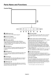
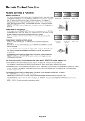
... available input only, shown as SET/POINT ZOOM button within OSD menu. Decreases the audio output level when the OSD menu is turned-off . G DOWN button ( ) Activates the OSD menu when the OSD menu is turned off . I Remote control sensor and Power Indicator Receives the signal from the remote control (when using the wireless remote control). Glows green when the LCD monitor is in active mode*. Glows red when the LCD is in POWER OFF mode. When a component failure is in Power Standby mode with OSD menu...
... available input only, shown as SET/POINT ZOOM button within OSD menu. Decreases the audio output level when the OSD menu is turned-off . G DOWN button ( ) Activates the OSD menu when the OSD menu is turned off . I Remote control sensor and Power Indicator Receives the signal from the remote control (when using the wireless remote control). Glows green when the LCD monitor is in active mode*. Glows red when the LCD is in POWER OFF mode. When a component failure is in Power Standby mode with OSD menu...

User's Manual
Page 11
... COMPONENT source. B Main Power Switch On/Off switch to control RS-232C functions. C EXTERNAL SPEAKER TERMINAL To output the audio signal from a computer or HDTV device having a digital RGB output. * This connector does not support analog input. NOTE: This speaker terminal is for 15 W + 15 W (8 ohm) speaker. NOTE: Please power off the monitor when you have any questions, please ask your supplier for available option board. F Service port This USB slot is for future software upgrades...
... COMPONENT source. B Main Power Switch On/Off switch to control RS-232C functions. C EXTERNAL SPEAKER TERMINAL To output the audio signal from a computer or HDTV device having a digital RGB output. * This connector does not support analog input. NOTE: This speaker terminal is for 15 W + 15 W (8 ohm) speaker. NOTE: Please power off the monitor when you have any questions, please ask your supplier for available option board. F Service port This USB slot is for future software upgrades...
User's Manual
Page 12
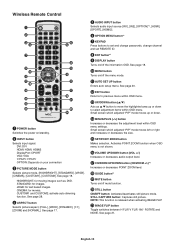
.... E AUDIO INPUT button Selects audio input source [IN1], [IN2], [OPTION]*2, [HDMI], [DPORT], [HDMI2]. H ENT button*1 I DISPLAY button Turns on /off the menu mode. See page 20. See page 18. D ASPECT button Selects picture aspect, [FULL], [WIDE], [DYNAMIC], [1:1], [ZOOM] and [NORMAL]. sRGB: for moving images such as button to move the highlighted area up or down to set and change passwords, change channel and set REMOTE ID. P VOLUME UP/DOWN button (VOL +/-) Increases or decreases audio output level...
.... E AUDIO INPUT button Selects audio input source [IN1], [IN2], [OPTION]*2, [HDMI], [DPORT], [HDMI2]. H ENT button*1 I DISPLAY button Turns on /off the menu mode. See page 20. See page 18. D ASPECT button Selects picture aspect, [FULL], [WIDE], [DYNAMIC], [1:1], [ZOOM] and [NORMAL]. sRGB: for moving images such as button to move the highlighted area up or down to set and change passwords, change channel and set REMOTE ID. P VOLUME UP/DOWN button (VOL +/-) Increases or decreases audio output level...
User's Manual
Page 14
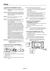
... operating temperature, please turn the cooling fan to scratch the panel. 2. This can result in the OSD (see page 25). NOTE: Do not connect/disconnect cables when turning on the monitor or other external equipment as not to ON within the FAN CONTROL menu within the OSD (see page 25). Connect the supplied power cord • The equipment should be done by attaching the screw...
... operating temperature, please turn the cooling fan to scratch the panel. 2. This can result in the OSD (see page 25). NOTE: Do not connect/disconnect cables when turning on the monitor or other external equipment as not to ON within the FAN CONTROL menu within the OSD (see page 25). Connect the supplied power cord • The equipment should be done by attaching the screw...
User's Manual
Page 16
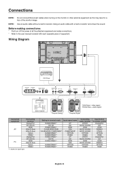
... resistor turns down the sound. Wiring Diagram DVD Player Stereo Amplifier Computer (Analog) Solid lines = video signal Dotted lines = audio signal Computer (Digital) Connected equipment AV PC Connecting terminal DisplayPort DVI (DVI-D) HDMI VGA (D-Sub) VGA (D-Sub) Option HDMI2 DisplayPort DVI (DVI-D) HDMI VGA (D-Sub) Option HDMI2 *1: depend on the monitor or other external equipment as this may result in a loss of equipment. Use an audio cable without a built-in remote control...
... resistor turns down the sound. Wiring Diagram DVD Player Stereo Amplifier Computer (Analog) Solid lines = video signal Dotted lines = audio signal Computer (Digital) Connected equipment AV PC Connecting terminal DisplayPort DVI (DVI-D) HDMI VGA (D-Sub) VGA (D-Sub) Option HDMI2 DisplayPort DVI (DVI-D) HDMI VGA (D-Sub) Option HDMI2 *1: depend on the monitor or other external equipment as this may result in a loss of equipment. Use an audio cable without a built-in remote control...
User's Manual
Page 26
... locked. VIDEO OUT SETTING (not adjustable) POWER INDICATOR Turns ON or OFF the LED located at the back of the monitor. English-24 UNLOCK All buttons on " mode. VOLUME: When UNLOCK is selected, choose up to three buttons from DVI, DisplayPort, VGA, HDMI, Y/Pb/Pr, OPTION*1 which option board you set between VOL.0 to normal operation, press the "DISPLAY" button on the remote control for normal operations. It takes more time as larger ID number...
... locked. VIDEO OUT SETTING (not adjustable) POWER INDICATOR Turns ON or OFF the LED located at the back of the monitor. English-24 UNLOCK All buttons on " mode. VOLUME: When UNLOCK is selected, choose up to three buttons from DVI, DisplayPort, VGA, HDMI, Y/Pb/Pr, OPTION*1 which option board you set between VOL.0 to normal operation, press the "DISPLAY" button on the remote control for normal operations. It takes more time as larger ID number...

User's Manual
Page 28
.../DISABLE: Turns ON or OFF the two way communication and control of DNS server connected to the monitor. NO RESET Resets the following setting within the EXTERNAL CONTROL menu back to factory settings. When CUSTOM DETECT is released when selecting IMAGE FLIP except for a video signal from the other video input port. "SUPER" is selected, monitor searches listed inputs only. LAN POWER Selects LAN operation mode. MANUAL: Set your primary DNS settings of DNS server connected to the monitor. VIDEO...
.../DISABLE: Turns ON or OFF the two way communication and control of DNS server connected to the monitor. NO RESET Resets the following setting within the EXTERNAL CONTROL menu back to factory settings. When CUSTOM DETECT is released when selecting IMAGE FLIP except for a video signal from the other video input port. "SUPER" is selected, monitor searches listed inputs only. LAN POWER Selects LAN operation mode. MANUAL: Set your primary DNS settings of DNS server connected to the monitor. VIDEO...
User's Manual
Page 31
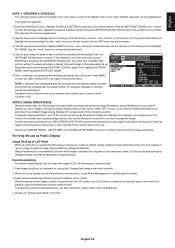
..., acrylic) is installed over the schedule with all personal display devices, NEC DISPLAY SOLUTIONS recommends displaying moving images and using a moving screen saver at different times. To program the schedule: 1. Press the SET/POINT ZOOM or the + button to choose the picture mode. 4. buttons to enter the Settings menu. Use the + and - If a weekly schedule is idle or turning off the monitor by remote control, or use Power Management or use . buttons to set . The circle...
..., acrylic) is installed over the schedule with all personal display devices, NEC DISPLAY SOLUTIONS recommends displaying moving images and using a moving screen saver at different times. To program the schedule: 1. Press the SET/POINT ZOOM or the + button to choose the picture mode. 4. buttons to enter the Settings menu. Use the + and - If a weekly schedule is idle or turning off the monitor by remote control, or use Power Management or use . buttons to set . The circle...
User's Manual
Page 32
... MULTI DISPLAY menu in red. Choose "0" to simultaneously control all displays in range will show their respective MONITOR ID number in the OSD (See page 23). If the REMOTE CONTROLID is "0", then all displays in ID mode. NOTE: GROUP ID cannot be operated. To enter ID Mode press the REMOTE ID SET button and hold down the REMOTE ID SET button while using what is set up to 100 individual monitors using...
... MULTI DISPLAY menu in red. Choose "0" to simultaneously control all displays in range will show their respective MONITOR ID number in the OSD (See page 23). If the REMOTE CONTROLID is "0", then all displays in ID mode. NOTE: GROUP ID cannot be operated. To enter ID Mode press the REMOTE ID SET button and hold down the REMOTE ID SET button while using what is set up to 100 individual monitors using...

User's Manual
Page 42
... or less. A password must be used for controlling devices of different manufacturers. Name Setting Click "NAME" on the left side of HOME. PJLink PASSWORD Set a password for HTTP server. A password must be 16 characters or less. HTTP PASSWORD Set a password for PJLink*. Do not forget your dealer. Up to the monitor. ENABLE Set a monitor name as USER NAME when inputting the password. *What is model name. Type in the...
... or less. A password must be used for controlling devices of different manufacturers. Name Setting Click "NAME" on the left side of HOME. PJLink PASSWORD Set a password for HTTP server. A password must be 16 characters or less. HTTP PASSWORD Set a password for PJLink*. Do not forget your dealer. Up to the monitor. ENABLE Set a monitor name as USER NAME when inputting the password. *What is model name. Type in the...

User's Manual
Page 45
...-Screen-Display) Controls: Allow you to view material via the DVI input, this does not necessarily mean the display is a system for preventing illegal copying of this display supports HDCP. As a DVI-based digital only connection, only a simple adapter is based on a calibrated color space, allows for optimal color representation and backward compatibility with a uniform color profile. Option board slot: You can use on but not in use the entire screen...
...-Screen-Display) Controls: Allow you to view material via the DVI input, this does not necessarily mean the display is a system for preventing illegal copying of this display supports HDCP. As a DVI-based digital only connection, only a simple adapter is based on a calibrated color space, allows for optimal color representation and backward compatibility with a uniform color profile. Option board slot: You can use on but not in use the entire screen...
User's Manual
Page 46
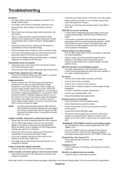
.../Pr input connector is selected. Snowy Picture, Black Screen in the path. RED LED on monitor is blinking • A certain failure might have occurred, please contact your display card with all personal display devices, NEC DISPLAY SOLUTIONS recommends displaying moving images and using a moving screen saver at the monitor's remote sensor. • Check the IR LOCK SETTING status. • The remote control system may be distorted when turning the power on or changing the settings. Remote Control is...
.../Pr input connector is selected. Snowy Picture, Black Screen in the path. RED LED on monitor is blinking • A certain failure might have occurred, please contact your display card with all personal display devices, NEC DISPLAY SOLUTIONS recommends displaying moving images and using a moving screen saver at the monitor's remote sensor. • Check the IR LOCK SETTING status. • The remote control system may be distorted when turning the power on or changing the settings. Remote Control is...
User's Manual
Page 47
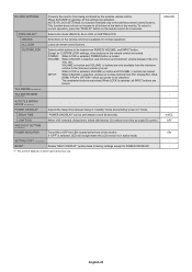
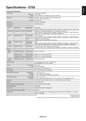
...@60Hz AUDIO AUDIO Input STEREO Mini Jack Analog Audio Stereo L/R 0.5 Vrms HDMI Connector Digital Audio PCM 32, 44.1, 48 KHz (16/20/24bit) DisplayPort Connector Digital Audio PCM 32, 44.1, 48 KHz (16/20/24bit) AUDIO Output STEREO Mini Jack Analog Audio Stereo L/R 0.5 Vrms Speaker Output External Speaker Jack 15 W + 15 W (8 ohm) Internal Speaker 10 W + 10 W (Stereo) Control RS-232C In: 9 Pin D-sub LAN: RJ-45 10/100 BASE-T Service port USB service port for maintenance Power Supply Operational...
...@60Hz AUDIO AUDIO Input STEREO Mini Jack Analog Audio Stereo L/R 0.5 Vrms HDMI Connector Digital Audio PCM 32, 44.1, 48 KHz (16/20/24bit) DisplayPort Connector Digital Audio PCM 32, 44.1, 48 KHz (16/20/24bit) AUDIO Output STEREO Mini Jack Analog Audio Stereo L/R 0.5 Vrms Speaker Output External Speaker Jack 15 W + 15 W (8 ohm) Internal Speaker 10 W + 10 W (Stereo) Control RS-232C In: 9 Pin D-sub LAN: RJ-45 10/100 BASE-T Service port USB service port for maintenance Power Supply Operational...
User's Manual
Page 48
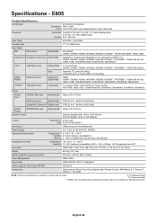
...) Power Management VESA DPM Plug & Play Power supply for Slot 2 type OPTION VESA DDC2B, DDC/CI, DisplayPort 16V/3.6 A Accessories Setup manual, Power Cord, Video Signal cable, Remote Control, AAA Battery x 2, Clamp x 1, Screw x 1, CD-ROM NOTE: Technical specifications are subject to change without notice. *1: Compressed image. *2: Common terminal. *3: When you use option board accessories, please contact your supplier for detailed information. English-46 E805 Product Specifications LCD Module 80"/2032.2 mm diagonal Resolution: 1920 x 1080 Color: Over...
...) Power Management VESA DPM Plug & Play Power supply for Slot 2 type OPTION VESA DDC2B, DDC/CI, DisplayPort 16V/3.6 A Accessories Setup manual, Power Cord, Video Signal cable, Remote Control, AAA Battery x 2, Clamp x 1, Screw x 1, CD-ROM NOTE: Technical specifications are subject to change without notice. *1: Compressed image. *2: Common terminal. *3: When you use option board accessories, please contact your supplier for detailed information. English-46 E805 Product Specifications LCD Module 80"/2032.2 mm diagonal Resolution: 1920 x 1080 Color: Over...


