

KT-LFD-CC Spec Brochure
Page 1
... data, allowing for quick and easy switching between calibration settings without reducing the number of different tone response curves also can be made to adjusting the intensity (luminance) and white point of America, Inc. Single displays to a 10x10 video wall are supported Product specifications are subject to change. 12/11 ver. 1. ©2011 NEC Display Solutions of the displays, the software also calibrates the grayscale using RS-232 or...
... data, allowing for quick and easy switching between calibration settings without reducing the number of different tone response curves also can be made to adjusting the intensity (luminance) and white point of America, Inc. Single displays to a 10x10 video wall are supported Product specifications are subject to change. 12/11 ver. 1. ©2011 NEC Display Solutions of the displays, the software also calibrates the grayscale using RS-232 or...

X Series SuperSlim Specification Brochure
Page 1
... components, simplifying installations •• Built-in tuner available for broadcast applications (-AVT models) •• TileMatrix™ technology enables video walls (up to 100 displays in tiled environments •• Ethernet Control and Communication provides the highest level of public displays. Large-Screen LCD NEC X401S, X461S and X551S 40", 46" and 55" LED edge-lit, super-slim professional-grade LCD displays A new class of remote display...
... components, simplifying installations •• Built-in tuner available for broadcast applications (-AVT models) •• TileMatrix™ technology enables video walls (up to 100 displays in tiled environments •• Ethernet Control and Communication provides the highest level of public displays. Large-Screen LCD NEC X401S, X461S and X551S 40", 46" and 55" LED edge-lit, super-slim professional-grade LCD displays A new class of remote display...

X Series SuperSlim Specification Brochure
Page 2
...MODEL X401S X461S X551S LCD MODULE Panel Technology Viewable Image Size Native Resolution Brightness (Typical/Maximum) Contrast Ratio (Typical) Viewing Angle Aspect Ratio Active Screen Area (W x H) Orientation Displayable Colors CONNECTIVITY Supported Video Formats PC/Mac Signal Compatibility Input Terminals Digital Analog Audio External Control Output Terminals Digital Audio External Control Digital Tuner POWER CONSUMPTiON On (Typical) Power Saving Mode PHYSICAL SPECIFICATIONS Bezel Width (L/R, T/B) Net Dimensions (without stand) VESA Hole Configuration ENVIRONMENTAL CONDITIONS Operating...
...MODEL X401S X461S X551S LCD MODULE Panel Technology Viewable Image Size Native Resolution Brightness (Typical/Maximum) Contrast Ratio (Typical) Viewing Angle Aspect Ratio Active Screen Area (W x H) Orientation Displayable Colors CONNECTIVITY Supported Video Formats PC/Mac Signal Compatibility Input Terminals Digital Analog Audio External Control Output Terminals Digital Audio External Control Digital Tuner POWER CONSUMPTiON On (Typical) Power Saving Mode PHYSICAL SPECIFICATIONS Bezel Width (L/R, T/B) Net Dimensions (without stand) VESA Hole Configuration ENVIRONMENTAL CONDITIONS Operating...

User Manual
Page 2
...-9 Control Panel ...English-9 Terminal Panel ...English-10 Wireless Remote Control ...English-11 Operating Range for the Remote Control English-12 Setup ...English-13 Connections ...English-15 Wiring Diagram ...English-15 Connecting a Personal Computer English-16 Connecting a DVD Player or Computer with HDMI out English-16 Connecting a Computer with DisplayPort English-16 Basic Operation...English-17 Power ON and OFF Modes ...English-17 Power Indicator...English-18 Using Power Management ...English-18 Selecting a video source...English-18 Picture...
...-9 Control Panel ...English-9 Terminal Panel ...English-10 Wireless Remote Control ...English-11 Operating Range for the Remote Control English-12 Setup ...English-13 Connections ...English-15 Wiring Diagram ...English-15 Connecting a Personal Computer English-16 Connecting a DVD Player or Computer with HDMI out English-16 Connecting a Computer with DisplayPort English-16 Basic Operation...English-17 Power ON and OFF Modes ...English-17 Power Indicator...English-18 Using Power Management ...English-18 Selecting a video source...English-18 Picture...

User Manual
Page 5
... with standard signals. • Use the preset Color Setting. • Use non-interlaced signals. • Do not use a BS-approved power cord with molded plug having a black (13A) fuse installed for transporting. • If using the backside handle. The monitor should be installed close to a power outlet, which can properly dissipate. Do not mount or secure this product by using the cooling fan continuously, it is no user serviceable parts inside and...
... with standard signals. • Use the preset Color Setting. • Use non-interlaced signals. • Do not use a BS-approved power cord with molded plug having a black (13A) fuse installed for transporting. • If using the backside handle. The monitor should be installed close to a power outlet, which can properly dissipate. Do not mount or secure this product by using the cooling fan continuously, it is no user serviceable parts inside and...

User Manual
Page 8
... weakness that have no supporting internal structure. VESA Mounting Interface 300 mm 300 mm Mounting accessories can damage the monitor. Mounting on the table underneath the LCD. Figure 1 Figure 2 Figure 3 Screw for the option board slot over time, against earthquakes, unexpected vibrations, and other problems that can be subjected to support the monitor and mounting accessories. • DO NOT install in locations where a door or gate...
... weakness that have no supporting internal structure. VESA Mounting Interface 300 mm 300 mm Mounting accessories can damage the monitor. Mounting on the table underneath the LCD. Figure 1 Figure 2 Figure 3 Screw for the option board slot over time, against earthquakes, unexpected vibrations, and other problems that can be subjected to support the monitor and mounting accessories. • DO NOT install in locations where a door or gate...

User Manual
Page 11
... sensor. Control Key Lock Mode This control completely locks out access to previous menu. ¾ Remote control sensor and Power Indicator Receives the signal from the remote control (when using the wireless remote control). To resume user mode, press both and and hold simultaneously for more than 3 seconds. English Parts Name and Functions Control Panel ³ POWER button Switches the power on/off . These are available input only, shown as their factory preset name. ¿ PLUS button Acts as EXIT button within the monitor...
... sensor. Control Key Lock Mode This control completely locks out access to previous menu. ¾ Remote control sensor and Power Indicator Receives the signal from the remote control (when using the wireless remote control). To resume user mode, press both and and hold simultaneously for more than 3 seconds. English Parts Name and Functions Control Panel ³ POWER button Switches the power on/off . These are available input only, shown as their factory preset name. ¿ PLUS button Acts as EXIT button within the monitor...

User Manual
Page 12
... output the DVI signal from the HDMI connection, the HDMI input must be used with the supplied power cord. · Main Power Switch On/Off switch to an external device (stereo receiver, amplifier, etc.). NOTE: When attaching the SP-RM2 for available option board. ƻ Internal speaker English-10 Terminal Panel AUDIO OUT AUDIO IN 1 SPEAKER L SPEAKER R ³ AC IN connector Connects with an RGB, COMPONENT, SCART, VIDEO or S-VIDEO source. If you use a suitable signal cable...
... output the DVI signal from the HDMI connection, the HDMI input must be used with the supplied power cord. · Main Power Switch On/Off switch to an external device (stereo receiver, amplifier, etc.). NOTE: When attaching the SP-RM2 for available option board. ƻ Internal speaker English-10 Terminal Panel AUDIO OUT AUDIO IN 1 SPEAKER L SPEAKER R ³ AC IN connector Connects with an RGB, COMPONENT, SCART, VIDEO or S-VIDEO source. If you use a suitable signal cable...

User Manual
Page 13
... change passwords, change channel and set REMOTE ID. ¶ ENT button*2 º DISPLAY button Turns on /standby. · INPUT button Selects input signal. STILL CAPTURE button: Captures still picture. Small screen which adjusted "PIP" mode moves left or right. ƹ SET button Makes selection. ƺ VOLUME UP/DOWN button Increases or decreases audio output level. ƻ CH UP/DOWN button*2 Ƽ GUIDE button*2 ƽ MUTE button Turns on/off mute function. ƾ STILL button ON/OFF button: Activates/deactivates still picture mode. See page 19. English Wireless Remote Control...
... change passwords, change channel and set REMOTE ID. ¶ ENT button*2 º DISPLAY button Turns on /standby. · INPUT button Selects input signal. STILL CAPTURE button: Captures still picture. Small screen which adjusted "PIP" mode moves left or right. ƹ SET button Makes selection. ƺ VOLUME UP/DOWN button Increases or decreases audio output level. ƻ CH UP/DOWN button*2 Ƽ GUIDE button*2 ƽ MUTE button Turns on/off mute function. ƾ STILL button ON/OFF button: Activates/deactivates still picture mode. See page 19. English Wireless Remote Control...

User Manual
Page 15
... panel. 2. Screw Clamp A. B. C. English Setup 1. CAUTION: MOVING OR INSTALLING THE LCD MONITOR MUST BE DONE BY TWO OR MORE PEOPLE. Failure to cool. If the LCD is used in the OSD (see page 25). Install the remote control batteries The remote control is powered by using the "HEAT STATUS" control in an enclosed area or if the LCD panel is running, a "Caution" warning will turn on the monitor or other external...
... panel. 2. Screw Clamp A. B. C. English Setup 1. CAUTION: MOVING OR INSTALLING THE LCD MONITOR MUST BE DONE BY TWO OR MORE PEOPLE. Failure to cool. If the LCD is used in the OSD (see page 25). Install the remote control batteries The remote control is powered by using the "HEAT STATUS" control in an enclosed area or if the LCD panel is running, a "Caution" warning will turn on the monitor or other external...

User Manual
Page 17
... AUDIO IN1 AUDIO IN1 AUDIO IN1 AUDIO IN1 AUDIO IN1 DPORT HDMI Input button in resistor. NOTE: Use an audio cable without a built-in remote control DVI HDMI DVD/HD VIDEO S-VIDEO VIDEO DVD/HD VGA DVI DISPLAYPORT HDMI English-15 Wiring Diagram Solid lines = video signal Dotted lines = audio signal Stereo Amplifier DVD player with a built-in Terminal Mode DVI MODE: DVI-HD RAW/EXPAND*1 D-SUB MODE: SCART - Setting in resistor turns down the sound. Before making connections: * First turn off the power...
... AUDIO IN1 AUDIO IN1 AUDIO IN1 AUDIO IN1 AUDIO IN1 DPORT HDMI Input button in resistor. NOTE: Use an audio cable without a built-in remote control DVI HDMI DVD/HD VIDEO S-VIDEO VIDEO DVD/HD VGA DVI DISPLAYPORT HDMI English-15 Wiring Diagram Solid lines = video signal Dotted lines = audio signal Stereo Amplifier DVD player with a built-in Terminal Mode DVI MODE: DVI-HD RAW/EXPAND*1 D-SUB MODE: SCART - Setting in resistor turns down the sound. Before making connections: * First turn off the power...

User Manual
Page 24
... Expands a 16:9 letter box signal to factory settings except VOLUME. - display area is sent from the source. - H RESOLUTION Adjusts the horizontal size of PIP audio. SCHEDULE OFF TIMER Sets the monitor to use. - VGA input only INPUT RESOLUTION VGA input only If there is available. OFF SCHEDULE SETTINGS Creates a working schedule for the real-time clock. - *: The product you select "STEREO", adjust the balance of time. H ZOOM Amount of the screen image. AUTO ASPECT Select the aspect...
... Expands a 16:9 letter box signal to factory settings except VOLUME. - display area is sent from the source. - H RESOLUTION Adjusts the horizontal size of PIP audio. SCHEDULE OFF TIMER Sets the monitor to use. - VGA input only INPUT RESOLUTION VGA input only If there is available. OFF SCHEDULE SETTINGS Creates a working schedule for the real-time clock. - *: The product you select "STEREO", adjust the balance of time. H ZOOM Amount of the screen image. AUTO ASPECT Select the aspect...

User Manual
Page 27
... network administrator. This function has a limit depending on the cable you use this function, EXTERNAL CONTROL should be changed and fixed when "ON" is displayed. 15 Press + button, the bar will become darker. RESET Resets "MULTI DISPLAY" options back to factory - AUTO SCREEN SAVER Use the SCREEN SAVER function to reduce the risk of the display to the monitor from your DHCP server. OFF SIDE BORDER COLOR Adjusts the color...
... network administrator. This function has a limit depending on the cable you use this function, EXTERNAL CONTROL should be changed and fixed when "ON" is displayed. 15 Press + button, the bar will become darker. RESET Resets "MULTI DISPLAY" options back to factory - AUTO SCREEN SAVER Use the SCREEN SAVER function to reduce the risk of the display to the monitor from your DHCP server. OFF SIDE BORDER COLOR Adjusts the color...

User Manual
Page 28
... video source is supplied to the DVD/HD, SCART, VIDEO1, VIDEO2 or S-VIDEO input. This is best suited for other port, then the monitor switches the video source input port to the new found video source automatically. This setting is the default setting. CUSTOM DETECT Set the priority of signal associated with the D-SUB input. D-SUB MODE Selects the type of input signals. INPUT CHANGE Sets input change and keep to the monitor, the monitor will not search the other computer equipment is connected. COLOR...
... video source is supplied to the DVD/HD, SCART, VIDEO1, VIDEO2 or S-VIDEO input. This is best suited for other port, then the monitor switches the video source input port to the new found video source automatically. This setting is the default setting. CUSTOM DETECT Set the priority of signal associated with the D-SUB input. D-SUB MODE Selects the type of input signals. INPUT CHANGE Sets input change and keep to the monitor, the monitor will not search the other computer equipment is connected. COLOR...

User Manual
Page 29
... on the screen. Selects sound input signal. Monitor power is automatically "OFF" when connected PC is OFF or the monitor is turned off by OFF TIMER setting or SCHEDULE setting. Resets OSD options back to factory settings EXCEPT FOR: PICTURE MODE, VOLUME, SCHEDULE SETTINGS, DATE & TIME, ASPECT in PIP, SUB INPUT in order to Option board slot during power save mode. ON OFF ANALOG OFF OFF NO NO - - English-27 Allow the monitor to supply power to best display the...
... on the screen. Selects sound input signal. Monitor power is automatically "OFF" when connected PC is OFF or the monitor is turned off by OFF TIMER setting or SCHEDULE setting. Resets OSD options back to factory settings EXCEPT FOR: PICTURE MODE, VOLUME, SCHEDULE SETTINGS, DATE & TIME, ASPECT in PIP, SUB INPUT in order to Option board slot during power save mode. ON OFF ANALOG OFF OFF NO NO - - English-27 Allow the monitor to supply power to best display the...

User Manual
Page 30
... and press the SET button. If selected input or picture mode is not available now, disable input or picture mode is desired, choose the days of the week using the up and down buttons to highlight the minutes setting. Fixed image should be turned off the monitor for a long period of Image persistence. Change fixed images after short intervals. 2. When not in red. To reduce the...
... and press the SET button. If selected input or picture mode is not available now, disable input or picture mode is desired, choose the days of the week using the up and down buttons to highlight the minutes setting. Fixed image should be turned off the monitor for a long period of Image persistence. Change fixed images after short intervals. 2. When not in red. To reduce the...
User Manual
Page 31
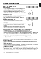
... DISPLAY" menu in red. The first monitor in the chain. Remote does not work Remote does not work In order for the display (See page 24). TO SET REMOTE CONTROL ID While holding down the REMOTE ID SET button while using what is shown on the display. The Monitor ID can then connect the RS-232C output from 1-100. In the "ADVANCED OPTION" menu on the remote control, use REMOTE ID:3 Remote works Use the remote control to operate a monitor that...
... DISPLAY" menu in red. The first monitor in the chain. Remote does not work Remote does not work In order for the display (See page 24). TO SET REMOTE CONTROL ID While holding down the REMOTE ID SET button while using what is shown on the display. The Monitor ID can then connect the RS-232C output from 1-100. In the "ADVANCED OPTION" menu on the remote control, use REMOTE ID:3 Remote works Use the remote control to operate a monitor that...

User Manual
Page 39
... as DFP and P&D. Plug and Play: The Microsoft® solution with accuracy while compensating for compatibility between computers and displays. VESA Standard (FDMIv1) Mounting Interface: Allows you to adjust the colors on but not in which certain content is a system for digital connections between DVI-D and other DVI-based digital connectors such as screen size and resolutions supported) directly to quickly and easily adjust all elements of this...
... as DFP and P&D. Plug and Play: The Microsoft® solution with accuracy while compensating for compatibility between computers and displays. VESA Standard (FDMIv1) Mounting Interface: Allows you to adjust the colors on but not in which certain content is a system for digital connections between DVI-D and other DVI-based digital connectors such as screen size and resolutions supported) directly to quickly and easily adjust all elements of this...

User Manual
Page 40
..., a RED LED will blink six times. Power on the display again after confirming the inside temperature being used . (Please consult display card or system manual to change the video mode to noninterlace and use . "SCHEDULE"/"OFF TIMER" function is not working properly • The "SCHEDULE" function will be disabled when the "OFF TIMER" is set at regular intervals whenever the screen is idle or turning off when the power supply...
..., a RED LED will blink six times. Power on the display again after confirming the inside temperature being used . (Please consult display card or system manual to change the video mode to noninterlace and use . "SCHEDULE"/"OFF TIMER" function is not working properly • The "SCHEDULE" function will be disabled when the "OFF TIMER" is set at regular intervals whenever the screen is idle or turning off when the power supply...

User Manual
Page 41
... 40°C Dimension 925.1 (W) x 537.1 (H) x 55.6 (D) mm / 36.4 (W) x 21.1 (H) x 2.2 (D) inches (with Standard V1.1a, applicable to change without handle and stand holder) Weight 14.9 kg (32.8 lbs) VESA compatible mounting interface 300 mm x 300 mm (M6, 4 Holes) Power Management VESA DPM Plug & Play VESA DDC2B, DDC/CI, DisplayPort Accessories Setup manual, Power Cord, Video Signal cable, Remote Control, AA Battery x 2, Clamp x 1, Screw x 1, CD-ROM, Option board slot screw x 2, Option board slot cover, Wall mount adapter x 4, Wall mount adapter screw x 4, Cushion for...
... 40°C Dimension 925.1 (W) x 537.1 (H) x 55.6 (D) mm / 36.4 (W) x 21.1 (H) x 2.2 (D) inches (with Standard V1.1a, applicable to change without handle and stand holder) Weight 14.9 kg (32.8 lbs) VESA compatible mounting interface 300 mm x 300 mm (M6, 4 Holes) Power Management VESA DPM Plug & Play VESA DDC2B, DDC/CI, DisplayPort Accessories Setup manual, Power Cord, Video Signal cable, Remote Control, AA Battery x 2, Clamp x 1, Screw x 1, CD-ROM, Option board slot screw x 2, Option board slot cover, Wall mount adapter x 4, Wall mount adapter screw x 4, Cushion for...


