Manual
Page 2
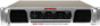
... and Protect LED indicators for the subs! Please read this manual carefully to get the most demanding sound reinforcement installation and touring applications. • This 3-way amp allows you .... • Filter / Source switch - Rear Panel 5 INSTALLATION 6 1. Inspection 6 2. Amplifier Cooling 6 INPUT CONNECTIONS 6 SPEAKER CONNECTIONS 7 SPECIFICATIONS 9 NOTES 10 Date of the finest power amplifiers on the... Name City State Zip Model # Serial # 2 to power your left and right input signals for selecting NADY AUDIO as your new 3WA-1700 amplifier has superior performance and...
... and Protect LED indicators for the subs! Please read this manual carefully to get the most demanding sound reinforcement installation and touring applications. • This 3-way amp allows you .... • Filter / Source switch - Rear Panel 5 INSTALLATION 6 1. Inspection 6 2. Amplifier Cooling 6 INPUT CONNECTIONS 6 SPEAKER CONNECTIONS 7 SPECIFICATIONS 9 NOTES 10 Date of the finest power amplifiers on the... Name City State Zip Model # Serial # 2 to power your left and right input signals for selecting NADY AUDIO as your new 3WA-1700 amplifier has superior performance and...

Manual
Page 3
... type, size, and correct rating. 8. The product has been exposed to operate normally or exhibits a marked change in the user maintenance instructions. Care should be connected to a power supply only of time at a high volume level or at a level that produce ... INSTRUCTIONS When using the product. 2. Do not use this electronic device, basic precautions should : (1) be left plugged into , or liquid has been spilled onto the product. Replace the fuse only with other servicing should consult an audiologist. 5. The power supply cord should always be referred to service the...
... type, size, and correct rating. 8. The product has been exposed to operate normally or exhibits a marked change in the user maintenance instructions. Care should be connected to a power supply only of time at a high volume level or at a level that produce ... INSTRUCTIONS When using the product. 2. Do not use this electronic device, basic precautions should : (1) be left plugged into , or liquid has been spilled onto the product. Replace the fuse only with other servicing should consult an audiologist. 5. The power supply cord should always be referred to service the...

Manual
Page 4
.... CONTROLS AND CONNECTIONS FRONT PANEL (4) (2) (3) (7) (6) (7) (1) (5) (6) (5) 1. Before turning on . The actual voltage gain is DC voltage at levels in dB. A momentary muting is blown, correct the problem (or unplug the speaker) and try turning the amp back on the amplifier, check all your other connected equipment.) 2. This can occur if the output...
.... CONTROLS AND CONNECTIONS FRONT PANEL (4) (2) (3) (7) (6) (7) (1) (5) (6) (5) 1. Before turning on . The actual voltage gain is DC voltage at levels in dB. A momentary muting is blown, correct the problem (or unplug the speaker) and try turning the amp back on the amplifier, check all your other connected equipment.) 2. This can occur if the output...

Manual
Page 5
... SPEAKER CONNECTIONS section on the rear panel and in excess of another amplifier by the Nady Service Department. 5 Make sure all connections are tidy and there are used as this can...to allow proper ventilation. 14. POWER CONNECTOR The cord connector is needed to find the frequency setting that could short the outputs. BALANCED INPUT CONNECTORS (1/4" TRS & XLR) These balanced 1/4" (6....binding post connections. Balanced input signals are recommended, as depicted on page 7 of this manual. [Caution: Make sure that prolonged use less than 600Ω output impedance is used...
... SPEAKER CONNECTIONS section on the rear panel and in excess of another amplifier by the Nady Service Department. 5 Make sure all connections are tidy and there are used as this can...to allow proper ventilation. 14. POWER CONNECTOR The cord connector is needed to find the frequency setting that could short the outputs. BALANCED INPUT CONNECTORS (1/4" TRS & XLR) These balanced 1/4" (6....binding post connections. Balanced input signals are recommended, as depicted on page 7 of this manual. [Caution: Make sure that prolonged use less than 600Ω output impedance is used...
Manual
Page 6
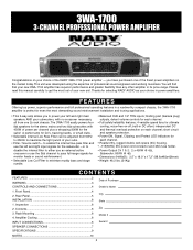
... shipment. INSPECTION Your 3WA-1700 amplifier was carefully packed at the factory in packaging designed to support the amps also in a timely manner.) CONTENTS • Instruction manual • 3WA-1700 (verify that may have occurred in transit. (Note: Nady Systems is not responsible for mobile use where the amps will be subjected to install your NADY AUDIO 3WA-1700 amplifier, please read...
... shipment. INSPECTION Your 3WA-1700 amplifier was carefully packed at the factory in packaging designed to support the amps also in a timely manner.) CONTENTS • Instruction manual • 3WA-1700 (verify that may have occurred in transit. (Note: Nady Systems is not responsible for mobile use where the amps will be subjected to install your NADY AUDIO 3WA-1700 amplifier, please read...

Manual
Page 7
... • Mains & Subwoofer Mode (with external crossover) 1. Turn off the amplifier power switch before making any connections. (Note: Nady Systems assumes no liability for damaged speakers resulting from your crossover into Channels 1 and 2. 2. Input main Left and Right signals from... a speaker load less than 4Ω to install your amplifier into the Subwoofer input. 3. Set the Filter/Source switch to find the setting that delivers the best sound from your subwoofer cabinet(s). 4. SPEAKER CONNECTIONS The following instructions describe the most common ways to either channel ...
... • Mains & Subwoofer Mode (with external crossover) 1. Turn off the amplifier power switch before making any connections. (Note: Nady Systems assumes no liability for damaged speakers resulting from your crossover into Channels 1 and 2. 2. Input main Left and Right signals from... a speaker load less than 4Ω to install your amplifier into the Subwoofer input. 3. Set the Filter/Source switch to find the setting that delivers the best sound from your subwoofer cabinet(s). 4. SPEAKER CONNECTIONS The following instructions describe the most common ways to either channel ...
Manual
Page 8
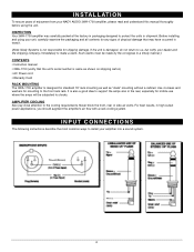
Set the Filter/Source switch to either channel as it can damage your crossover into the Subwoofer input. 3. Input main Left and Right signals from your mixer into Channels 1 and 2. 2. AUX SEND/ MONITOR L R 4Ω min + - 4Ω min + - 8Ω 8Ω R 8Ω 8Ω MONITORS SOUND REINFORCEMENT (Note: Do not connect a speaker load less than 4Ω to OFF. SPEAKER CONNECTIONS • Mains & Monitor Mode 1. Input Monitor or Aux full-range signal from your amplifier.) 4Ω min + - 8Ω 8Ω L 8
Set the Filter/Source switch to either channel as it can damage your crossover into the Subwoofer input. 3. Input main Left and Right signals from your mixer into Channels 1 and 2. 2. AUX SEND/ MONITOR L R 4Ω min + - 4Ω min + - 8Ω 8Ω R 8Ω 8Ω MONITORS SOUND REINFORCEMENT (Note: Do not connect a speaker load less than 4Ω to OFF. SPEAKER CONNECTIONS • Mains & Monitor Mode 1. Input Monitor or Aux full-range signal from your amplifier.) 4Ω min + - 8Ω 8Ω L 8
Manual
Page 9
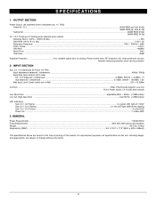
...Sub balanced / unbalanced ...-2.1dBm, 600mV / +3.8dBm, 1.2V Max Input Level (Level control set to change without prior notice. 9 DC offset protection circuits; For improvement purposes, all channels ... Noise Floor ...3mV Total Gain ...40dB Amplifier Protection Four variable speed fans for this manual. RF protection; short circuit protection 2. GENERAL Power Requirements ...115VAC/60Hz Fuse Requirements ......21Kg) Dimensions (HWD) ...3.5" x 19.0" x 17.2" (88.8 x 483 x 436mm) The specifications above are subject to Mid) ...>5V, +16.2dBm Controls ...Rear: Filter/Source selector, Low Cut...
...Sub balanced / unbalanced ...-2.1dBm, 600mV / +3.8dBm, 1.2V Max Input Level (Level control set to change without prior notice. 9 DC offset protection circuits; For improvement purposes, all channels ... Noise Floor ...3mV Total Gain ...40dB Amplifier Protection Four variable speed fans for this manual. RF protection; short circuit protection 2. GENERAL Power Requirements ...115VAC/60Hz Fuse Requirements ......21Kg) Dimensions (HWD) ...3.5" x 19.0" x 17.2" (88.8 x 483 x 436mm) The specifications above are subject to Mid) ...>5V, +16.2dBm Controls ...Rear: Filter/Source selector, Low Cut...

Manual
Page 11
DO NOT ATTEMPT TO SERVICE THIS UNIT YOURSELF AS IT CAN BE DANGEROUS AND WILL ALSO VOID THE WARRANTY. NADY SYSTEMS, INC. • 6701 SHELLMOUND STREET, EMERYVILLE, CA 94608 Tel: 510.652.2411 • Fax: 510.652.5075 • nady.com SERVICE FOR YOUR NADY AUDIO PRODUCT (U.S.) Should your NADY AUDIO product require service, please contact the Nady Service Department via telephone at (510) 652-2411, or e-mail at service@nady.com. (International) For service, please contact the NADY AUDIO distributor in your country through the dealer from whom you purchased this product.
DO NOT ATTEMPT TO SERVICE THIS UNIT YOURSELF AS IT CAN BE DANGEROUS AND WILL ALSO VOID THE WARRANTY. NADY SYSTEMS, INC. • 6701 SHELLMOUND STREET, EMERYVILLE, CA 94608 Tel: 510.652.2411 • Fax: 510.652.5075 • nady.com SERVICE FOR YOUR NADY AUDIO PRODUCT (U.S.) Should your NADY AUDIO product require service, please contact the Nady Service Department via telephone at (510) 652-2411, or e-mail at service@nady.com. (International) For service, please contact the NADY AUDIO distributor in your country through the dealer from whom you purchased this product.