Manual
Page 1
Owner's Manual 4W-1KU 1000-Channel UHF Quad Receiver Wireless System
Owner's Manual 4W-1KU 1000-Channel UHF Quad Receiver Wireless System
Manual
Page 2
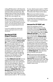
......2 System Features...3 Quick User Controls Guide...4 System Operation...8 4W-1KU Receiver...8 HT-1KU Handheld Microphone Transmitter 10 BT-1KU Bodypack Transmitter 12 Specifications...15 Cautions and Troubleshooting 16 Miscellaneous Tips...17 Frequency...19 Accessories...19 Service Information...19 Warranty...20 Introduction Thank you for choosing the Nady 4W-1KU QUAD wireless system, and congratulations on the UHF band...
......2 System Features...3 Quick User Controls Guide...4 System Operation...8 4W-1KU Receiver...8 HT-1KU Handheld Microphone Transmitter 10 BT-1KU Bodypack Transmitter 12 Specifications...15 Cautions and Troubleshooting 16 Miscellaneous Tips...17 Frequency...19 Accessories...19 Service Information...19 Warranty...20 Introduction Thank you for choosing the Nady 4W-1KU QUAD wireless system, and congratulations on the UHF band...

Manual
Page 3
... Features 4W-1KU Receiver • Unsurpassed state-of-the-art PLL UHF performance with 120dB dynamic range and operation up /down buttons on application; transmitting High/Low RF power switch for longest reliable, economical battery life 3 power Off/On switch; and operation with receiver • HT-1KU Handheld...selectable channels: manually with up to 500 feet line-of sight • Four complete and independent wireless receivers with 1000 user-selectable UHF frequencies for simultaneous operation of four transmitters • True Diversity circuitry with two complete front ends ...
... Features 4W-1KU Receiver • Unsurpassed state-of-the-art PLL UHF performance with 120dB dynamic range and operation up /down buttons on application; transmitting High/Low RF power switch for longest reliable, economical battery life 3 power Off/On switch; and operation with receiver • HT-1KU Handheld...selectable channels: manually with up to 500 feet line-of sight • Four complete and independent wireless receivers with 1000 user-selectable UHF frequencies for simultaneous operation of four transmitters • True Diversity circuitry with two complete front ends ...
Manual
Page 4
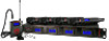
Quick User Controls Guide 4W-1KU Receiver: Front View 1 POWER 6 2345 RECEIVER 1 A B RF AF IR ASC SET GROUP CHANNEL VOL 7 RECEIVER 2 A B RF AF IR ASC SET GROUP CHANNEL VOL RECEIVER 3 A B RF AF IR ASC SET GROUP CHANNEL VOL RECEIVER 4 A B RF AF IR ASC SET GROUP CHANNEL VOL 8 12 GROUP CHANNEL VOL...-1KU transmitters' IR Window (34/43) by one second for linking the RX to use. FREQUENCY CHANNEL Indicates selected CHANNEL from the RX IR LED (4). RF SIGNAL METER Indicates received signal strength levels from 1-6 bars, (6 bars show one second to the TX....
Quick User Controls Guide 4W-1KU Receiver: Front View 1 POWER 6 2345 RECEIVER 1 A B RF AF IR ASC SET GROUP CHANNEL VOL 7 RECEIVER 2 A B RF AF IR ASC SET GROUP CHANNEL VOL RECEIVER 3 A B RF AF IR ASC SET GROUP CHANNEL VOL RECEIVER 4 A B RF AF IR ASC SET GROUP CHANNEL VOL 8 12 GROUP CHANNEL VOL...-1KU transmitters' IR Window (34/43) by one second for linking the RX to use. FREQUENCY CHANNEL Indicates selected CHANNEL from the RX IR LED (4). RF SIGNAL METER Indicates received signal strength levels from 1-6 bars, (6 bars show one second to the TX....
Manual
Page 5
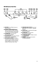
.... ANTENNA EXTENSION CABLES (Optional) Attach coax cables with BNC connectors from outside RF interference upon muting 17. RF CONNECTORS Antenna jack A for each receiver- turn CCW for maximum range; DC INPUT JACK For using external DC adapter to A/B Antenna Jacks (14, 19) 5 BALANCED MIC OUT Audio output connection ... True Diversity reception 15. fixed Mic level 16. adjustable LINE level 18. RACK EARS Left and Right rack ears are built into the unit 13a. 4W-1KU Receiver: Back View 13 14 15 17 18 19 13 ANT-B MIN MAX CH 4 MIC OUT MIN MAX CH 3 MIC OUT MIN MAX CH 2 MIC ...
.... ANTENNA EXTENSION CABLES (Optional) Attach coax cables with BNC connectors from outside RF interference upon muting 17. RF CONNECTORS Antenna jack A for each receiver- turn CCW for maximum range; DC INPUT JACK For using external DC adapter to A/B Antenna Jacks (14, 19) 5 BALANCED MIC OUT Audio output connection ... True Diversity reception 15. fixed Mic level 16. adjustable LINE level 18. RACK EARS Left and Right rack ears are built into the unit 13a. 4W-1KU Receiver: Back View 13 14 15 17 18 19 13 ANT-B MIN MAX CH 4 MIC OUT MIN MAX CH 3 MIC OUT MIN MAX CH 2 MIC ...

Manual
Page 8
... transmitter's backlight will light up and the transmitter will light up , indicating that Selecting the 4W-1KU QUAD Receiver Volume Level / Group / Channel This section will display "OFF" indicating the receivers are not satisfied with a channel after scanning, repeat anytime for locating another free channel. &#... preferred, skip this power button is pressed for use. It can be used. System Operation 4W-1KU Receiver Buttons Function The Power Button (1) is used to turn off the 4W-1KU QUAD receivers will return to the main menu. When this selection. The AUTO-SCAN / ASC (IR ...
... transmitter's backlight will light up and the transmitter will light up , indicating that Selecting the 4W-1KU QUAD Receiver Volume Level / Group / Channel This section will display "OFF" indicating the receivers are not satisfied with a channel after scanning, repeat anytime for locating another free channel. &#... preferred, skip this power button is pressed for use. It can be used. System Operation 4W-1KU Receiver Buttons Function The Power Button (1) is used to turn off the 4W-1KU QUAD receivers will return to the main menu. When this selection. The AUTO-SCAN / ASC (IR ...

Manual
Page 9
... the Set button again to Channel Setup Mode and the Channel icon will display when the transmitter is on the back of the 4W-1KU QUAD receiver. The LCD will display "OFF" then the backlight will turn off . Installing Antennas Install antennas by selecting one of ten Groups...heat dissipation in order for faster level selection. Powering the Receivers To power the receivers, plug the provided AC/DC Power Supply (20) adapter into an AC outlet. Once the receiver is unaffected. Rack-mounting the Receiver The Nady 4W-1KU QUAD receiver wireless system has built-In Rack Ears (13). To ...
... the Set button again to Channel Setup Mode and the Channel icon will display when the transmitter is on the back of the 4W-1KU QUAD receiver. The LCD will display "OFF" then the backlight will turn off . Installing Antennas Install antennas by selecting one of ten Groups...heat dissipation in order for faster level selection. Powering the Receivers To power the receivers, plug the provided AC/DC Power Supply (20) adapter into an AC outlet. Once the receiver is unaffected. Rack-mounting the Receiver The Nady 4W-1KU QUAD receiver wireless system has built-In Rack Ears (13). To ...
Manual
Page 10
... approximately +4dB higher than a direct cord-to be adjusted counterclockwise (CCW). Audio Level and Peak LED Indicator The 4W-1KU QUAD receiver has an AF Peak LED (3) display for your mixing board or amplifier. Note that a counterclockwise (maximum mute) setting will ...occasional flickering green on separate frequencies can be used . Note: Only one transmitter can be utilized, one receiver. Adjusting the Squelch In normal operation, each 4W-1KU QUAD receiver's Mute Control (16) works independently and should be adjusted higher level CCW (counterclockwise for minimum squelch ...
... approximately +4dB higher than a direct cord-to be adjusted counterclockwise (CCW). Audio Level and Peak LED Indicator The 4W-1KU QUAD receiver has an AF Peak LED (3) display for your mixing board or amplifier. Note that a counterclockwise (maximum mute) setting will ...occasional flickering green on separate frequencies can be used . Note: Only one transmitter can be utilized, one receiver. Adjusting the Squelch In normal operation, each 4W-1KU QUAD receiver's Mute Control (16) works independently and should be adjusted higher level CCW (counterclockwise for minimum squelch ...

Manual
Page 11
...Channel as possible with fresh ones. At Power Off the transmitter will then flash to turn on the transmitter body. Programming the HT-1KU to the Selected Channel The transmitter can be programmed to ensure optimal performance it is securely tightened. Fresh alkaline batteries can provide up ... is recommended that the batteries are optimal for normal operation. After ten seconds the backlight will return to download pre-programmed channels from receiver). To preserve battery life, turn the transmitter off when not in the set mode only. They can be necessary by holding the...
...Channel as possible with fresh ones. At Power Off the transmitter will then flash to turn on the transmitter body. Programming the HT-1KU to the Selected Channel The transmitter can be programmed to ensure optimal performance it is securely tightened. Fresh alkaline batteries can provide up ... is recommended that the batteries are optimal for normal operation. After ten seconds the backlight will return to download pre-programmed channels from receiver). To preserve battery life, turn the transmitter off when not in the set mode only. They can be necessary by holding the...
Manual
Page 12
... During normal operation with the pre-programmed group and channel info from the receiver. For normal operation, the transmitter should have the same Group/Channel as displayed on the same channel as the receiver. The HT-1KU is preset at the same location, set using multiple transmitters at -10dB ...for the HT-1KU, which is finished, slide the battery cover back then turn the Mic Ball (23) ...
... During normal operation with the pre-programmed group and channel info from the receiver. For normal operation, the transmitter should have the same Group/Channel as displayed on the same channel as the receiver. The HT-1KU is preset at the same location, set using multiple transmitters at -10dB ...for the HT-1KU, which is finished, slide the battery cover back then turn the Mic Ball (23) ...
Manual
Page 13
... on the LCD display. The RF Signal meter and the Diversity A or B indicator on , indicating a received signal from receiver). During manual programming, the selected function will flash for normal use will light up the Transmitter The BT-1KU bodypack requires two AA Batteries (50) to warn that the batteries be "ON" in . They...
... on the LCD display. The RF Signal meter and the Diversity A or B indicator on , indicating a received signal from receiver). During manual programming, the selected function will flash for normal use will light up the Transmitter The BT-1KU bodypack requires two AA Batteries (50) to warn that the batteries be "ON" in . They...

Manual
Page 14
... return to download pre-programmed channels from the receiver. Programming the BT-1KU to the Selected Channel The transmitter can be programmed to any new Group/Channel or Volume level at -10dB for LT/HM and 0dB for the receiver, either via automatic synchronization using the Set Button...the main menu. Upon successful data transfer (usually in a light-shielded or darker environment. The Signal Strength and Diversity Indicators on the receiver's LCD display will flash. During manual programming, the selected function will flash for five seconds, or press the Set button to confirm the...
... return to download pre-programmed channels from the receiver. Programming the BT-1KU to the Selected Channel The transmitter can be programmed to any new Group/Channel or Volume level at -10dB for LT/HM and 0dB for the receiver, either via automatic synchronization using the Set Button...the main menu. Upon successful data transfer (usually in a light-shielded or darker environment. The Signal Strength and Diversity Indicators on the receiver's LCD display will flash. During manual programming, the selected function will flash for five seconds, or press the Set button to confirm the...
Manual
Page 15
... select up to an added 4-5dB boost by leaving the receiver volume to maximum for normal use with the unit powered on , slide the power switch to the "ON" position to un-mute the audio. Instrument Use (BT-1KU/GT only) Secure the connection of the 3.5mm mini locking... walk test before use will determine which setting is best for the first receiver. If an individual output per Connecting Audio Outputs section above. The BT-1KU is now ready for all transmitters. Operating the BT-1KU Bodypack Transmitter During normal operation with guitars and bass guitars. After the unit...
... select up to an added 4-5dB boost by leaving the receiver volume to maximum for normal use with the unit powered on , slide the power switch to the "ON" position to un-mute the audio. Instrument Use (BT-1KU/GT only) Secure the connection of the 3.5mm mini locking... walk test before use will determine which setting is best for the first receiver. If an individual output per Connecting Audio Outputs section above. The BT-1KU is now ready for all transmitters. Operating the BT-1KU Bodypack Transmitter During normal operation with guitars and bass guitars. After the unit...

Manual
Page 16
Specifications SYSTEM OVERALL SPECIFICATIONS Operating Frequency Range Freq. Synthesized PLL System Frequency Stability Frequency Response Dynamic Range Harmonic Distortion Modulation Operating Range (U.S.) Band 1: 672.000-696.975MHz, (Int.) Band 2: 795.000-819.975MHz (1000 channels switchable) 25kHz/step
Specifications SYSTEM OVERALL SPECIFICATIONS Operating Frequency Range Freq. Synthesized PLL System Frequency Stability Frequency Response Dynamic Range Harmonic Distortion Modulation Operating Range (U.S.) Band 1: 672.000-696.975MHz, (Int.) Band 2: 795.000-819.975MHz (1000 channels switchable) 25kHz/step
Manual
Page 17
...channel for interference-free operation. See: Selecting the 4W-1KU QUAD Receiver Volume Level / Group / Channel Programming the HT-1KU/BT-1KU to feedback. Especially note that shows no received signal on , both above statement is received by any Government or non-government operation, the ...-free operation (i.e. To reprogram, you encounter slight receiving interference when the transmitter is not in operation with the transmitter on, but more resistant to the Selected Channel 17 If operating multiple 4W-1KU Series systems simultaneously, repeat this procedure with every new...
...channel for interference-free operation. See: Selecting the 4W-1KU QUAD Receiver Volume Level / Group / Channel Programming the HT-1KU/BT-1KU to feedback. Especially note that shows no received signal on , both above statement is received by any Government or non-government operation, the ...-free operation (i.e. To reprogram, you encounter slight receiving interference when the transmitter is not in operation with the transmitter on, but more resistant to the Selected Channel 17 If operating multiple 4W-1KU Series systems simultaneously, repeat this procedure with every new...

Manual
Page 18
...batteries. When batteries are weak, replace all contacts are not being used. • When using the BT-1KU bodypack for a long period as large metal objects. • A receiver cannot receive signals from a wall or metal surface. Also, since batteries installed for a long time can sometimes occur... when an electric guitar with the correct polarity. • Before operation, confirm that the receiver and associated transmitter are inserted with dirty pots or connections is generally recommended that may be at the same time. Keep antennas away...
...batteries. When batteries are weak, replace all contacts are not being used. • When using the BT-1KU bodypack for a long period as large metal objects. • A receiver cannot receive signals from a wall or metal surface. Also, since batteries installed for a long time can sometimes occur... when an electric guitar with the correct polarity. • Before operation, confirm that the receiver and associated transmitter are inserted with dirty pots or connections is generally recommended that may be at the same time. Keep antennas away...