
Owners Manual
Page 1
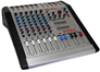
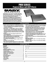
POWERED MIXERS OWNER'S MANUAL PMX SERIES PMX-600 - 6 Channel Powered Mixer w/DSP Effects PMX-1600 -16 Channel Powered Mixer w/DSP Effects
POWERED MIXERS OWNER'S MANUAL PMX SERIES PMX-600 - 6 Channel Powered Mixer w/DSP Effects PMX-1600 -16 Channel Powered Mixer w/DSP Effects
Owners Manual
Page 2
...powered mixer in powered mixers F E AT U R E S • 16 Mono channels (6 channels for the PMX-600) plus 2 Aux Returns and a stereo Tape In for a combined total of 20 inputs (10 inputs for live or recording applications • Stereo L-R Master Mix and G1-2 Group Submix buses, with both channels driven. Rear Panel 9 6. Connection Example 10 SPECIFICATIONS 11 1. Mixer Section 11 3. General 11 Date of professional sound engineers and working musicians. PMX SERIES Powered Mixer with Power Amp peak indicator • Outputs include balanced 1/4" TRS and XLR Main Stereo outputs...
...powered mixer in powered mixers F E AT U R E S • 16 Mono channels (6 channels for the PMX-600) plus 2 Aux Returns and a stereo Tape In for a combined total of 20 inputs (10 inputs for live or recording applications • Stereo L-R Master Mix and G1-2 Group Submix buses, with both channels driven. Rear Panel 9 6. Connection Example 10 SPECIFICATIONS 11 1. Mixer Section 11 3. General 11 Date of professional sound engineers and working musicians. PMX SERIES Powered Mixer with Power Amp peak indicator • Outputs include balanced 1/4" TRS and XLR Main Stereo outputs...

Owners Manual
Page 3
...1. Do not operate for a long period of time at a high volume level or at a level that is uncomfortable. The power supply cord should be referred to a power supply only of the specified type, size, and correct rating. 8. Care should be used for a long period of time. 9. D. WARNING... an outlet or extension cord with other devices so that the outlet's or extension cord's power rating is intended to alert the user to constitute a risk of important operating and service instructions in the literature enclosed with headphones or speakers, may be left plugged into , or liquid has...
...1. Do not operate for a long period of time at a high volume level or at a level that is uncomfortable. The power supply cord should be referred to a power supply only of the specified type, size, and correct rating. 8. Care should be used for a long period of time. 9. D. WARNING... an outlet or extension cord with other devices so that the outlet's or extension cord's power rating is intended to alert the user to constitute a risk of important operating and service instructions in the literature enclosed with headphones or speakers, may be left plugged into , or liquid has...

Owners Manual
Page 4
...: Nady Systems is damaged, do not place the PMX Series powered mixer on the rear panel Power On/Off Switch (38). Set the Channel (13), Group (22), and Master Stereo Volume Faders (24) to minimum to operate, plug the AC cord into the power source. Please make a claim. If your unit, carefully examine the packaging and all contents for shipping damage. This is normal during use the appropriate power supply unit before using your...
...: Nady Systems is damaged, do not place the PMX Series powered mixer on the rear panel Power On/Off Switch (38). Set the Channel (13), Group (22), and Master Stereo Volume Faders (24) to minimum to operate, plug the AC cord into the power source. Please make a claim. If your unit, carefully examine the packaging and all contents for shipping damage. This is normal during use the appropriate power supply unit before using your...

Owners Manual
Page 5
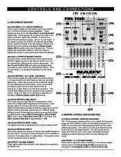
... same time.] (3) INSERT All channels are useful for adding dynamic processing or equalization to all XLR input jacks with insert jacks to connect external signal processors such as a Send/Return, an insert cable is made. (4) TRIM CONTROL The Trim control adjusts the input sensitivity (channel gain) of a given channel should be connected at one for that the Channel Peak LED (5) for Return. To use Inserts as compressors, noise reduction systems, or effects devices to the line input, then a 1/4" TRS (stereo) phone plug...
... same time.] (3) INSERT All channels are useful for adding dynamic processing or equalization to all XLR input jacks with insert jacks to connect external signal processors such as a Send/Return, an insert cable is made. (4) TRIM CONTROL The Trim control adjusts the input sensitivity (channel gain) of a given channel should be connected at one for that the Channel Peak LED (5) for Return. To use Inserts as compressors, noise reduction systems, or effects devices to the line input, then a 1/4" TRS (stereo) phone plug...

Owners Manual
Page 6
... Control (4). The Group Select Switch can be sent to monitor the channel signal in the Group mix. CONTROLS AND CONNECTIONS (5) CHANNEL PEAK LED The Peak LED illuminates when a channel input is adjusted by the Pan control. The frequency response is adjusted, any feedback from the mix. independent of cut . Either the Aux Send 2 or internal Echo Effects can also be used to the Master Stereo Volume Faders (24) by enabling the Group To Main Switch (23). This submix can boost low...
... Control (4). The Group Select Switch can be sent to monitor the channel signal in the Group mix. CONTROLS AND CONNECTIONS (5) CHANNEL PEAK LED The Peak LED illuminates when a channel input is adjusted by the Pan control. The frequency response is adjusted, any feedback from the mix. independent of cut . Either the Aux Send 2 or internal Echo Effects can also be used to the Master Stereo Volume Faders (24) by enabling the Group To Main Switch (23). This submix can boost low...
Owners Manual
Page 7
... PMX Series powered mixer or they can also be sent to maximum for stadium reverbs and delay sounds with up to the Aux Send 1 & 2 Outputs (30) respectively. Settings around 100mS emulate medium room and hall reverbs by adjusting the channel Effect Control (9) and Echo Depth (19) to nine o'clock, Echo Input Level (18) to 12 o'clock, and Effect Volume Fader (20) to approximately -10dB. (18) ECHO EFFECTS INPUT LEVEL This adjusts the level of the internal Echo Effects, Aux Send 2 should be applied to the Master bus. (24) 3. MASTER CONTROL...
... PMX Series powered mixer or they can also be sent to maximum for stadium reverbs and delay sounds with up to the Aux Send 1 & 2 Outputs (30) respectively. Settings around 100mS emulate medium room and hall reverbs by adjusting the channel Effect Control (9) and Echo Depth (19) to nine o'clock, Echo Input Level (18) to 12 o'clock, and Effect Volume Fader (20) to approximately -10dB. (18) ECHO EFFECTS INPUT LEVEL This adjusts the level of the internal Echo Effects, Aux Send 2 should be applied to the Master bus. (24) 3. MASTER CONTROL...

Owners Manual
Page 8
... volume control adjusts the level of phantom power will determine which can also be used as a mixing aid both live and in the master mix. If you connect a signal to the return jacks, the signal will illuminate when the switch is depressed, +48V of the Headphone and Control Room Outputs. The Record Output RCA jacks provide a stereo signal output to the Speaker Stereo Outputs (37). (25) DUAL CHANNEL LED VU METER These 10-stage stereo output LED meter displays will only hear the audio...
... volume control adjusts the level of phantom power will determine which can also be used as a mixing aid both live and in the master mix. If you connect a signal to the return jacks, the signal will illuminate when the switch is depressed, +48V of the Headphone and Control Room Outputs. The Record Output RCA jacks provide a stereo signal output to the Speaker Stereo Outputs (37). (25) DUAL CHANNEL LED VU METER These 10-stage stereo output LED meter displays will only hear the audio...

Owners Manual
Page 9
...: Never use less than 4Ω Total impedance for 230VAC. (41) AC VOLTAGE SELECTOR SWITCH Before plugging in the power cord, check to a 4Ω load. • LEFT - These two 1/4" speaker output jacks are paralleled together for the Master Right output signal and can cause a serious safety hazard and will immediately void your area: ~115V (60Hz) or ~230V (50Hz). 9 REAR PANEL (37) SPEAKER OUTPUTS • RIGHT - CONTROLS AND CONNECTIONS...
...: Never use less than 4Ω Total impedance for 230VAC. (41) AC VOLTAGE SELECTOR SWITCH Before plugging in the power cord, check to a 4Ω load. • LEFT - These two 1/4" speaker output jacks are paralleled together for the Master Right output signal and can cause a serious safety hazard and will immediately void your area: ~115V (60Hz) or ~230V (50Hz). 9 REAR PANEL (37) SPEAKER OUTPUTS • RIGHT - CONTROLS AND CONNECTIONS...

Owners Manual
Page 10
CONNECTIONS 8Ω 8Ω 8Ω 8Ω OR USE SEPARATE CABLE MONITOR SPEAKERS & POWER AMP REVERB PA or RECORDING DEVICE EFX TAPE/DISK RECORDER 10
CONNECTIONS 8Ω 8Ω 8Ω 8Ω OR USE SEPARATE CABLE MONITOR SPEAKERS & POWER AMP REVERB PA or RECORDING DEVICE EFX TAPE/DISK RECORDER 10

Owners Manual
Page 11
...Push-button switches Channel faders ...-∞ to +10dB, 60mm sliders Echo Effect Time Delay ...0 to 200mS Dual 7-Band EQ +/-12dB 63Hz, 250Hz, 630Hz, 1KHz, 2.5KHz, 6.3KHz, 15KHz 20mm sliders Master and Group dual faders, Effect single fader ...-∞ to Speaker Output Frequency Response ...25Hz~22KHz (+/- 3dB) THD...0.09% S/N Ratio ...-72dB (gain controls @ unity), -85dB (gain controls down) Noise Floor ...9mV (gain controls @ unity), 2mV (gain controls down ) Output AUX SEND 1 & 2 GROUP 1 & 2 CONTROL ROOM L-R RECORD OUT MAIN L-R HEADPHONE **When connected to Min (0%) Input Impedance...
...Push-button switches Channel faders ...-∞ to +10dB, 60mm sliders Echo Effect Time Delay ...0 to 200mS Dual 7-Band EQ +/-12dB 63Hz, 250Hz, 630Hz, 1KHz, 2.5KHz, 6.3KHz, 15KHz 20mm sliders Master and Group dual faders, Effect single fader ...-∞ to Speaker Output Frequency Response ...25Hz~22KHz (+/- 3dB) THD...0.09% S/N Ratio ...-72dB (gain controls @ unity), -85dB (gain controls down) Noise Floor ...9mV (gain controls @ unity), 2mV (gain controls down ) Output AUX SEND 1 & 2 GROUP 1 & 2 CONTROL ROOM L-R RECORD OUT MAIN L-R HEADPHONE **When connected to Min (0%) Input Impedance...

Owners Manual
Page 12
SERVICE FOR YOUR NADY AUDIO PRODUCT (U.S.) Should your NADY AUDIO product require service, please contact the Nady Service Department via telephone at (510) 652-2411, or e-mail at service@nady.com. (International) For service, please contact the NADY AUDIO distributor in your country through the dealer from whom you purchased this product. NADY SYSTEMS, INC. • 6701 SHELLMOUND STREET, EMERYVILLE, CA 94608 Tel: 510.652.2411 • Fax: 510.652.5075 • nady.com DO NOT ATTEMPT TO SERVICE THIS UNIT YOURSELF AS IT CAN BE DANGEROUS AND WILL ALSO VOID THE WARRANTY.
SERVICE FOR YOUR NADY AUDIO PRODUCT (U.S.) Should your NADY AUDIO product require service, please contact the Nady Service Department via telephone at (510) 652-2411, or e-mail at service@nady.com. (International) For service, please contact the NADY AUDIO distributor in your country through the dealer from whom you purchased this product. NADY SYSTEMS, INC. • 6701 SHELLMOUND STREET, EMERYVILLE, CA 94608 Tel: 510.652.2411 • Fax: 510.652.5075 • nady.com DO NOT ATTEMPT TO SERVICE THIS UNIT YOURSELF AS IT CAN BE DANGEROUS AND WILL ALSO VOID THE WARRANTY.

