

Instruction Manual
Page 2
... Wi-Fi is a registered trademark of the warning decals. TABLE OF CONTENTS WARNING DECAL PLACEMENT 2 IMPORTANT PRECAUTIONS 3 BEFORE YOU BEGIN 5 PART IDENTIFICATION CHART 6 ASSEMBLY 7 THE CHEST HEART RATE MONITOR 12 HOW TO USE THE INCLINE TRAINER 13 HOW TO MOVE THE INCLINE TRAINER 25 MAINTENANCE AND TROUBLESHOOTING 26 EXERCISE... 35 ORDERING REPLACEMENT PARTS Back Cover RECYCLING INFORMATION Back Cover WARNING DECAL PLACEMENT This drawing shows the locations of Wi-Fi Alliance. NORDICTRACK and IFIT are registered trademarks of this manual and request a free replacement decal.
... Wi-Fi is a registered trademark of the warning decals. TABLE OF CONTENTS WARNING DECAL PLACEMENT 2 IMPORTANT PRECAUTIONS 3 BEFORE YOU BEGIN 5 PART IDENTIFICATION CHART 6 ASSEMBLY 7 THE CHEST HEART RATE MONITOR 12 HOW TO USE THE INCLINE TRAINER 13 HOW TO MOVE THE INCLINE TRAINER 25 MAINTENANCE AND TROUBLESHOOTING 26 EXERCISE... 35 ORDERING REPLACEMENT PARTS Back Cover RECYCLING INFORMATION Back Cover WARNING DECAL PLACEMENT This drawing shows the locations of Wi-Fi Alliance. NORDICTRACK and IFIT are registered trademarks of this manual and request a free replacement decal.
Instruction Manual
Page 4
.... SAVE THESE INSTRUCTIONS 4 be performed by an authorized service representative. Always unplug the power cord immediately after use . 24. The incline trainer is properly assembled. (See ASSEMBLY on page 7, and HOW TO MOVE THE INCLINE TRAINER on the incline trainer. 26. 20. The heart rate monitor is not in serious injury or...
.... SAVE THESE INSTRUCTIONS 4 be performed by an authorized service representative. Always unplug the power cord immediately after use . 24. The incline trainer is properly assembled. (See ASSEMBLY on page 7, and HOW TO MOVE THE INCLINE TRAINER on the incline trainer. 26. 20. The heart rate monitor is not in serious injury or...

Instruction Manual
Page 6
Note: If a part is not in parentheses below to see whether it is the quantity used for assembly. Extra parts may be included. 3/8" Star Washer (3)-12 3/8" x 5 1/2" Screw (1)-4 6 The number in the hardware kit, check to identify small parts used for assembly. PART IDENTIFICATION CHART Use the drawings below each drawing is the key number of the part, from the PART LIST near the end of this manual. The number following the key number is preattached.
Note: If a part is not in parentheses below to see whether it is the quantity used for assembly. Extra parts may be included. 3/8" Star Washer (3)-12 3/8" x 5 1/2" Screw (1)-4 6 The number in the hardware kit, check to identify small parts used for assembly. PART IDENTIFICATION CHART Use the drawings below each drawing is the key number of the part, from the PART LIST near the end of this manual. The number following the key number is preattached.

Instruction Manual
Page 7
... damaging parts, do not have internet access, call Customer Service (see the front cover of this manual) 7 ASSEMBLY • Assembly requires two persons. • To identify small parts, see page 6. • Place all assembly steps. • Assembly requires the following information to the email address or postal address on the exterior of the incline...
... damaging parts, do not have internet access, call Customer Service (see the front cover of this manual) 7 ASSEMBLY • Assembly requires two persons. • To identify small parts, see page 6. • Place all assembly steps. • Assembly requires the following information to the email address or postal address on the exterior of the incline...
Instruction Manual
Page 10
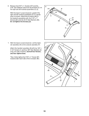
... one side is shown); Do not tighten the Screws yet. 65 85 C E 7. With the help of a second person, set the handrail assembly (D) on 6 the right and left handrail assemblies (D, E). 87 D With the help of the Crossbar (85). 85 D 87 F 1 3 1 10 start all four Screws, and then tighten... them. Remove the 5/16" x 1" Screws (87) and the 5/16" Star Washers (65) from the brackets (C) on the console assembly (F). 7 Attach the handrail assembly (D) with the 5/16" x 1" 87 Screws (87) and the 5/16" Star Washers (65). Then, firmly tighten the 5/16" x 1" Screw (87...
... one side is shown); Do not tighten the Screws yet. 65 85 C E 7. With the help of a second person, set the handrail assembly (D) on 6 the right and left handrail assemblies (D, E). 87 D With the help of the Crossbar (85). 85 D 87 F 1 3 1 10 start all four Screws, and then tighten... them. Remove the 5/16" x 1" Screws (87) and the 5/16" Star Washers (65) from the brackets (C) on the console assembly (F). 7 Attach the handrail assembly (D) with the 5/16" x 1" 87 Screws (87) and the 5/16" Star Washers (65). Then, firmly tighten the 5/16" x 1" Screw (87...


