
User Manual English etc.
Page 1
INTEGRATED AMPLIFIER A-9130 Instruction Manual Before use 2 Preparations 8 Basic Operations 16 En Fr Es Others 20
INTEGRATED AMPLIFIER A-9130 Instruction Manual Before use 2 Preparations 8 Basic Operations 16 En Fr Es Others 20

User Manual English etc.
Page 2
...; Instruction Manual (This document) 0 Connect speakers with Onkyo RI Components ...........11 Using this unit as a power amplifier 12 Power Cord Hookup 12 Setup 13 Remote controller preparations 13 Turn on the power of equipment manufactured by other companies. 0 Specifications and appearance are subject to power amplifier mode ...... 19 Others Useful functions 20 Setting auto standby 20 Troubleshooting...
...; Instruction Manual (This document) 0 Connect speakers with Onkyo RI Components ...........11 Using this unit as a power amplifier 12 Power Cord Hookup 12 Setup 13 Remote controller preparations 13 Turn on the power of equipment manufactured by other companies. 0 Specifications and appearance are subject to power amplifier mode ...... 19 Others Useful functions 20 Setting auto standby 20 Troubleshooting...

User Manual English etc.
Page 3
...REFER SERVICING TO QUALIFIED SERVICE PERSONNEL. To prevent fire hazard, the openings should be set 10 cm (4") away from overheating. Do not use for a replacement. Important Notice The model number...intended to alert the user to the presence of important operating and maintenance (servicing) instructions in the literature accompanying the appliance. REFER SERVICING TO QUALIFIED SERVICE PERSONNEL. Record these ...power cord when your waste disposal service or the point of sale where you an electrical shock. WEEE http://www.onkyo.com/manual/weee/weee.pdf En 3 If ...
...REFER SERVICING TO QUALIFIED SERVICE PERSONNEL. To prevent fire hazard, the openings should be set 10 cm (4") away from overheating. Do not use for a replacement. Important Notice The model number...intended to alert the user to the presence of important operating and maintenance (servicing) instructions in the literature accompanying the appliance. REFER SERVICING TO QUALIFIED SERVICE PERSONNEL. Record these ...power cord when your waste disposal service or the point of sale where you an electrical shock. WEEE http://www.onkyo.com/manual/weee/weee.pdf En 3 If ...

User Manual English etc.
Page 5
... with a subwoofer cable. (p9) En 5 RI REMOTE CONTROL jack: This jack is connected. 6. To select the input source for linking when you connect an Onkyo CD player, tuner, network audio player, or RI dock that uses an MM type cartridge. (p10) 7. PHONO (MM) jacks: Use an Analog audio cable...
... with a subwoofer cable. (p9) En 5 RI REMOTE CONTROL jack: This jack is connected. 6. To select the input source for linking when you connect an Onkyo CD player, tuner, network audio player, or RI dock that uses an MM type cartridge. (p10) 7. PHONO (MM) jacks: Use an Analog audio cable...
User Manual English etc.
Page 6
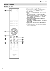
SETUP button: Switches to On or Standby. 2. Remote Controller Operating this unit Before use 1. Í button: Sets this unit to the settings menu. MUTING button: Temporarily mutes audio. PM BASS button: Switch the PHASE MATCHING BASS feature on ... DIRECT button: Switch the DIRECT feature on and off . (p18) 9. Make speaker impedance settings (p14), RI function settings (p15), subwoofer output settings (p17), and auto standby settings (p20). 6. RETURN button: Returns the display to be played. 5. Press again to confirm...
SETUP button: Switches to On or Standby. 2. Remote Controller Operating this unit Before use 1. Í button: Sets this unit to the settings menu. MUTING button: Temporarily mutes audio. PM BASS button: Switch the PHASE MATCHING BASS feature on ... DIRECT button: Switch the DIRECT feature on and off . (p18) 9. Make speaker impedance settings (p14), RI function settings (p15), subwoofer output settings (p17), and auto standby settings (p20). 6. RETURN button: Returns the display to be played. 5. Press again to confirm...

User Manual English etc.
Page 7
... RI dock Point the remote controller at the remote control sensor of this unit. You can operate Onkyo CD players, tuners, network audio players, and RI docks with the remote controller of the < and > buttons when you have a Network CD player,... the remote controller of this unit by connecting this unit and the other components Before use of this unit to the previous display/state during setting. 14.INPUT button 0 When using a network audio player, pressing the MENU button returns to operate. 12.Cursor buttons (D/C/B/A), ENTER button:...
... RI dock Point the remote controller at the remote control sensor of this unit. You can operate Onkyo CD players, tuners, network audio players, and RI docks with the remote controller of the < and > buttons when you have a Network CD player,... the remote controller of this unit by connecting this unit and the other components Before use of this unit to the previous display/state during setting. 14.INPUT button 0 When using a network audio player, pressing the MENU button returns to operate. 12.Cursor buttons (D/C/B/A), ENTER button:...
User Manual English etc.
Page 8
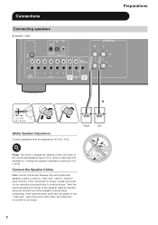
... when connecting. If the connection is wrong, a bass sound will be reproduced properly due to reverse phase. side to less than 8 ≠ impedance. Right Left Setup: You have to change the setting on this unit if any of the connected speakers have 4 ≠ or more to - Change the speaker impedance... setting to 4 ≠. (p14) Connect the Speaker Cables Make correct connection between the unit's jacks and speaker's jacks (+ side to 16 ≠. Connections Connecting speakers a ...
... when connecting. If the connection is wrong, a bass sound will be reproduced properly due to reverse phase. side to less than 8 ≠ impedance. Right Left Setup: You have to change the setting on this unit if any of the connected speakers have 4 ≠ or more to - Change the speaker impedance... setting to 4 ≠. (p14) Connect the Speaker Cables Make correct connection between the unit's jacks and speaker's jacks (+ side to 16 ≠. Connections Connecting speakers a ...
User Manual English etc.
Page 9
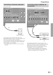
...player to the DIGITAL IN OPTICAL D2 jack. Alternatively, use the RI function. 0 Only PCM audio is recommended to set this off according to output PCM. Refer to "Connecting with Onkyo RI Components" (p11) to boost bass playback even more. En 9 Connecting a Powered subwoofer a Subwoofer Cable ...Set the audio output on /off if you are not using a subwoofer. You can also connect a Powered subwoofer to the SUBWOOFER PRE OUT jack to use a Digital optical cable to connect a player to the DIGITAL IN COAXIAL D1 jack. Use a subwoofer cable for details. 0 It is supported...
...player to the DIGITAL IN OPTICAL D2 jack. Alternatively, use the RI function. 0 Only PCM audio is recommended to set this off according to output PCM. Refer to "Connecting with Onkyo RI Components" (p11) to boost bass playback even more. En 9 Connecting a Powered subwoofer a Subwoofer Cable ...Set the audio output on /off if you are not using a subwoofer. You can also connect a Powered subwoofer to the SUBWOOFER PRE OUT jack to use a Digital optical cable to connect a player to the DIGITAL IN COAXIAL D1 jack. Use a subwoofer cable for details. 0 It is supported...

User Manual English etc.
Page 10
... has a built-in audio equalizer, connect it to one of the LINE IN 1/2/3/4/5 jacks. Also, if the turntable uses an MC type cartridge, install an audio equalizer compatible with Onkyo RI Components" (p11) to an LINE IN jack other than the PHONO (MM) jack. Connecting players (LINE IN connection) a Analog Audio...
... has a built-in audio equalizer, connect it to one of the LINE IN 1/2/3/4/5 jacks. Also, if the turntable uses an MC type cartridge, install an audio equalizer compatible with Onkyo RI Components" (p11) to an LINE IN jack other than the PHONO (MM) jack. Connecting players (LINE IN connection) a Analog Audio...

User Manual English etc.
Page 11
...instruction manual of this unit to centrally control components by connecting with an RI cable. When connecting to the DIGITAL IN COAXIAL D1 jack, use an Analog audio cable. Refer to the following table for details. (*)Setup: When connecting a CD player or tuner, settings...use the RI function. Connecting with Onkyo RI Components a RI Cable, b Digital Coaxial Cable a b CD Connection and Setup If you have an Onkyo CD player, tuner, network audio...used with the RI function. 0 Some functions may not be supported depending on the product even when an RI connection is used. ∫ Auto...
...instruction manual of this unit to centrally control components by connecting with an RI cable. When connecting to the DIGITAL IN COAXIAL D1 jack, use an Analog audio cable. Refer to the following table for details. (*)Setup: When connecting a CD player or tuner, settings...use the RI function. Connecting with Onkyo RI Components a RI Cable, b Digital Coaxial Cable a b CD Connection and Setup If you have an Onkyo CD player, tuner, network audio...used with the RI function. 0 Some functions may not be supported depending on the product even when an RI connection is used. ∫ Auto...

User Manual English etc.
Page 12
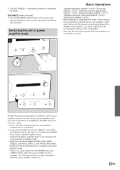
Doing so may produce high-volume sound that can use this unit as a power amplifier. This model includes a removable power cord. Make sure you can damage the unit, speakers, and various other connections are completed. Always disconnect the outlet side first when ...disconnecting the power cord. The power cord must be connected only after all other devices. Setup: Switch the unit to power amplifier mode to use this unit as a power amplifier. (p19) 12 Connect the MAIN IN jacks of the unit...
Doing so may produce high-volume sound that can use this unit as a power amplifier. This model includes a removable power cord. Make sure you can damage the unit, speakers, and various other connections are completed. Always disconnect the outlet side first when ...disconnecting the power cord. The power cord must be connected only after all other devices. Setup: Switch the unit to power amplifier mode to use this unit as a power amplifier. (p19) 12 Connect the MAIN IN jacks of the unit...

User Manual English etc.
Page 14
...2", "LINE 3" and "LINE 4" indicators are blinking 4. Press SETUP on this unit is set to be used as "LINE 1" and "LINE 2", start blinking. (BLINKING) 0 The indicators blink and the current setting is required. 1. Check the setting. (p19) 2. Refer to the page describing speaker connection ... if the change is displayed. 3 3. To exit the settings, press SETUP. 0 The setting mode ends after 5 seconds elapse with no operations performed. 4Ω 8Ω 14 Speaker impedance settings 1 Preparations / // SETUP Depending on the speakers you connect, you may need to ...
...2", "LINE 3" and "LINE 4" indicators are blinking 4. Press SETUP on this unit is set to be used as "LINE 1" and "LINE 2", start blinking. (BLINKING) 0 The indicators blink and the current setting is required. 1. Check the setting. (p19) 2. Refer to the page describing speaker connection ... if the change is displayed. 3 3. To exit the settings, press SETUP. 0 The setting mode ends after 5 seconds elapse with no operations performed. 4Ω 8Ω 14 Speaker impedance settings 1 Preparations / // SETUP Depending on the speakers you connect, you may need to ...

User Manual English etc.
Page 15
... COAXIAL D1 jack (default value): The "D1" indicator blinks and "LINE 1" lights. - RI function settings 1 2 3 (CD) Linked D1 Linked LINE IN 1 (Tuner) Linked D2 Linked LINE IN 2 Preparations / // SETUP When connecting an Onkyo CD player or tuner to the RI REMOTE CONTROL jack on this unit is... set to the DIGITAL IN OPTICAL D2 jack (default value): The "D2" indicator blinks and "LINE 2" lights. - To exit the settings, press SETUP. 0 The setting mode ends after 5 ...
... COAXIAL D1 jack (default value): The "D1" indicator blinks and "LINE 1" lights. - RI function settings 1 2 3 (CD) Linked D1 Linked LINE IN 1 (Tuner) Linked D2 Linked LINE IN 2 Preparations / // SETUP When connecting an Onkyo CD player or tuner to the RI REMOTE CONTROL jack on this unit is... set to the DIGITAL IN OPTICAL D2 jack (default value): The "D2" indicator blinks and "LINE 2" lights. - To exit the settings, press SETUP. 0 The setting mode ends after 5 ...

User Manual English etc.
Page 17
... unit enables you are connected, irrespective of the setting. 1. Check the setting. (p19) 2. To exit the settings, press SETUP. 0 The setting mode ends after 5 seconds elapse with the choices being "Auto" (default setting), "On", and "Off". Press SETUP on sound quality can be used as "LINE 1"... and "LINE 2", light on the remote controller to change the setting. - Press D/C on the remote controller several times so that some input source indicators, such as a power amplifier, the SETUP button will not work. Auto (default value): "LINE 1" and "LINE 2" ...
... unit enables you are connected, irrespective of the setting. 1. Check the setting. (p19) 2. To exit the settings, press SETUP. 0 The setting mode ends after 5 seconds elapse with the choices being "Auto" (default setting), "On", and "Off". Press SETUP on sound quality can be used as "LINE 1"... and "LINE 2", light on the remote controller to change the setting. - Press D/C on the remote controller several times so that some input source indicators, such as a power amplifier, the SETUP button will not work. Auto (default value): "LINE 1" and "LINE 2" ...
User Manual English etc.
Page 19
... as a power amplifier when you cancel the power amplifier mode, BASS, TREBLE, BALANCE, DIRECT, and PHASE MATCHING BASS revert to the settings prior to changing to the MAIN IN jack on this happens, you may automatically switch to cancel the power amplifier mode. If this unit... (p12). 0 Power amplifier modes settings are not available if headphones are also unavailable while the power amplifier mode is on the pre-amplifier. 0 Also read the instruction manual of the sounds output from the PHONES jack and LINE OUT jacks while...
... as a power amplifier when you cancel the power amplifier mode, BASS, TREBLE, BALANCE, DIRECT, and PHASE MATCHING BASS revert to the settings prior to changing to the MAIN IN jack on this happens, you may automatically switch to cancel the power amplifier mode. If this unit... (p12). 0 Power amplifier modes settings are not available if headphones are also unavailable while the power amplifier mode is on the pre-amplifier. 0 Also read the instruction manual of the sounds output from the PHONES jack and LINE OUT jacks while...
User Manual English etc.
Page 20
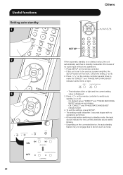
... MATCHING BASS" indicators either blink or light. 0 The indicators blink or light and the current setting value is on or off. - Press SETUP on the remote controller. 0 If this unit is set to switch auto standby on (default value), the unit automatically switches to standby mode after 5 ..., the auto standby feature may not engage due to factors such as a power amplifier, the SETUP button will not work. Check the setting. (p19) 2. To exit the settings, press SETUP. 0 The setting mode ends after 20 minutes of no operations performed. 0 60 seconds before switching to standby mode...
... MATCHING BASS" indicators either blink or light. 0 The indicators blink or light and the current setting value is on or off. - Press SETUP on the remote controller. 0 If this unit is set to switch auto standby on (default value), the unit automatically switches to standby mode after 5 ..., the auto standby feature may not engage due to factors such as a power amplifier, the SETUP button will not work. Check the setting. (p19) 2. To exit the settings, press SETUP. 0 The setting mode ends after 20 minutes of no operations performed. 0 60 seconds before switching to standby mode...

User Manual English etc.
Page 21
...seconds or more, then plug it back in a place with the metal part of speaker terminals. 0 Make sure that 's being used to unsuccessful ...as those from the wall outlet immediately and contact the dealer or customer support. Set the audio output on the playback device to output PCM. ∫.... 0 If you may be able to cancel. Troubleshooting Others Before starting the procedure Problems may be solved by increasing the volume on the pre...cord from an external source, or static electricity may output noise. 0 Install the integrated amplifier on a sturdy rack or shelf. Audio 0 Confirm...
...seconds or more, then plug it back in a place with the metal part of speaker terminals. 0 Make sure that 's being used to unsuccessful ...as those from the wall outlet immediately and contact the dealer or customer support. Set the audio output on the playback device to output PCM. ∫.... 0 If you may be able to cancel. Troubleshooting Others Before starting the procedure Problems may be solved by increasing the volume on the pre...cord from an external source, or static electricity may output noise. 0 Install the integrated amplifier on a sturdy rack or shelf. Audio 0 Confirm...
User Manual English etc.
Page 22
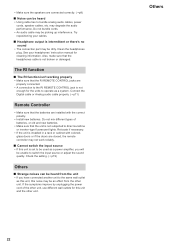
...for this unit and the other unit. 22 Others Try repositioning your headphones' instruction manual for cleaning information. Relocate if necessary. 0 If the unit is intermittent or there's no sound 0 The connection part may not work reliably. ∫ Cannot switch the input source 0 If ...Install new batteries. may degrade the audio performance, Do not bundle cords. 0 An audio cable may be an effect from the other unit, use different wall outlets for the units to operate as a power amplifier, you have connected another unit to the same wall outlet as this unit, this unit is set...
...for this unit and the other unit. 22 Others Try repositioning your headphones' instruction manual for cleaning information. Relocate if necessary. 0 If the unit is intermittent or there's no sound 0 The connection part may not work reliably. ∫ Cannot switch the input source 0 If ...Install new batteries. may degrade the audio performance, Do not bundle cords. 0 An audio cable may be an effect from the other unit, use different wall outlets for the units to operate as a power amplifier, you have connected another unit to the same wall outlet as this unit, this unit is set...
User Manual English etc.
Page 72
..., Upper Saddle River, N.J. 07458, U.S.A. For Dealer, Service, Order and all other Business Inquiries: Tel: 201-785-2600 Fax: 201-785-2650 http://www.us.onkyo.com/ For Product Support Team Only: 1-800-229-1687 http://www.us.onkyo.com/ Gutenbergstrasse 3, 82178 Puchheim, Germany Tel: +49...Road, Tsim Sha Tsui Kowloon, Hong Kong. Visit the Onkyo web site for the latest update. (C) Copyright 2018 Onkyo & Pioneer Corporation Japan. SN 29403409 F1807-0 *29403409* http://www.intl.onkyo.com/support/ The above-mentioned information is subject to Onkyo SUPPORT site. Tel: +852-2429-3118 Fax: +852-2428...
..., Upper Saddle River, N.J. 07458, U.S.A. For Dealer, Service, Order and all other Business Inquiries: Tel: 201-785-2600 Fax: 201-785-2650 http://www.us.onkyo.com/ For Product Support Team Only: 1-800-229-1687 http://www.us.onkyo.com/ Gutenbergstrasse 3, 82178 Puchheim, Germany Tel: +49...Road, Tsim Sha Tsui Kowloon, Hong Kong. Visit the Onkyo web site for the latest update. (C) Copyright 2018 Onkyo & Pioneer Corporation Japan. SN 29403409 F1807-0 *29403409* http://www.intl.onkyo.com/support/ The above-mentioned information is subject to Onkyo SUPPORT site. Tel: +852-2429-3118 Fax: +852-2428...

User Manual Simplified Chinese
Page 9
a DIGITAL IN 连接) a b a b a 调谐器 SUBWOOFER PRE OUT p17)。 0 CD DIGITAL IN COAXIAL D1 DIGITAL IN OPTICAL D2 RI Onkyo RI p11)。 0 DIGITAL IN OPTICAL/COAXIAL 支持 PCM PCM。 9
a DIGITAL IN 连接) a b a b a 调谐器 SUBWOOFER PRE OUT p17)。 0 CD DIGITAL IN COAXIAL D1 DIGITAL IN OPTICAL D2 RI Onkyo RI p11)。 0 DIGITAL IN OPTICAL/COAXIAL 支持 PCM PCM。 9
