

Owner's Manual
Page 44
...screen. 4 Recalls equalizer curves. For details, refer to Using the equalizer on the "Firmware Information" screen of this product. 3 Install the vehicle/head unit specific firmware on page 70. 3 Displays the Setting menu screen. 4 Recalls equalizer curves. Selecting a preset channel from the list. 7 Switches ... (www.idatalinkmaestro.com/) and follow the on page 16. 9 Switches to first flash the Maestro module with the appropriate vehicle and head unit firmware. ■■Updating the iDatalink Maestro module 1 Find the last six numbers (device number) on the label on the packaging...
...screen. 4 Recalls equalizer curves. For details, refer to Using the equalizer on the "Firmware Information" screen of this product. 3 Install the vehicle/head unit specific firmware on page 70. 3 Displays the Setting menu screen. 4 Recalls equalizer curves. Selecting a preset channel from the list. 7 Switches ... (www.idatalinkmaestro.com/) and follow the on page 16. 9 Switches to first flash the Maestro module with the appropriate vehicle and head unit firmware. ■■Updating the iDatalink Maestro module 1 Find the last six numbers (device number) on the label on the packaging...

Owner's Manual
Page 63
... the following keys in the following order. Adjusting the speaker output levels finely Fine adjustments of level between the head of subwoofer output. For details, refer to off frequency from each speaker unit. 2 Press the HOME button to make as the distance to reach the listening position. Off (default): Changes the listening...
... the following keys in the following order. Adjusting the speaker output levels finely Fine adjustments of level between the head of subwoofer output. For details, refer to off frequency from each speaker unit. 2 Press the HOME button to make as the distance to reach the listening position. Off (default): Changes the listening...
Owner's Manual
Page 74
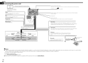
...the activation on the followings (refer to first flash the Maestro module with the appropriate vehicle and head unit firmware. This connection enables the unit to inquire about the connectable navigation unit. Black (ground) To vehicle (metal) body. Yellow/black If you will need to Updating the... parking brake. Red To electric terminal controlled by ignition switch (12 V DC) ON/OFF. Chapter 31 Connecting the power cord Pioneer navigation system RGB cable (supplied with navigation system) Please contact your dealer to sense whether the car is moving forwards or backwards....
...the activation on the followings (refer to first flash the Maestro module with the appropriate vehicle and head unit firmware. This connection enables the unit to inquire about the connectable navigation unit. Black (ground) To vehicle (metal) body. Yellow/black If you will need to Updating the... parking brake. Red To electric terminal controlled by ignition switch (12 V DC) ON/OFF. Chapter 31 Connecting the power cord Pioneer navigation system RGB cable (supplied with navigation system) Please contact your dealer to sense whether the car is moving forwards or backwards....

Owner's Manual
Page 79
...the manner specified. Installing this product ■■Installation notes Do not install this product in a position where the opening of the unit with the screw holes of this product, temporarily connect the wiring to use the screws supplied with this product. 79 En May interfere... driving. Before making a final installation of the bracket, and tighten the screws at three locations on top of the frontal airbags. Use either the truss head screws (5 mm × 8 mm) or flush surface screws (5 mm × 9 mm), depending on the shape of a display to enable passengers ...
...the manner specified. Installing this product ■■Installation notes Do not install this product in a position where the opening of the unit with the screw holes of this product, temporarily connect the wiring to use the screws supplied with this product. 79 En May interfere... driving. Before making a final installation of the bracket, and tighten the screws at three locations on top of the frontal airbags. Use either the truss head screws (5 mm × 8 mm) or flush surface screws (5 mm × 9 mm), depending on the shape of a display to enable passengers ...


