
Service Manual
Page 1
... 48 7.1 DISASSEMBLY 48 7.2 PARTS 49 7.2.1 IC 49 7.2.2 DISPLAY 54 8. PIONEER EUROPE N.V. PCB CONNECTION DIAGRAM 26 5. BLOCK DIAGRAM AND SCHEMATIC DIAGRAM ..... 8 4. PCB PARTS LIST 39 6. P.O. PHONES N∫m-Û≤?/ Digital Signal Processor MPX MODE 2/DTS SIGNAL SELECT R 1 MIDNIGHT @ @ AUDIO/VIDEO MULTI-CHANNEL RECEIVER VSX-D409 VSX-D309 ORDER NO. RRV2252 THIS MANUAL IS APPLICABLE TO...
... 48 7.1 DISASSEMBLY 48 7.2 PARTS 49 7.2.1 IC 49 7.2.2 DISPLAY 54 8. PIONEER EUROPE N.V. PCB CONNECTION DIAGRAM 26 5. BLOCK DIAGRAM AND SCHEMATIC DIAGRAM ..... 8 4. PCB PARTS LIST 39 6. P.O. PHONES N∫m-Û≤?/ Digital Signal Processor MPX MODE 2/DTS SIGNAL SELECT R 1 MIDNIGHT @ @ AUDIO/VIDEO MULTI-CHANNEL RECEIVER VSX-D409 VSX-D309 ORDER NO. RRV2252 THIS MANUAL IS APPLICABLE TO...
Service Manual
Page 40
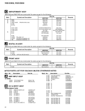
...used AKE1012 J DIGITAL IN ASSY AWX7476 and AWX7505 are constructed the same except for the following : Mark Symbol and Description C1901 R1901 JA1903 OPTICAL RECEIV MOD. Part No. Description Part No. Description C AMP&PRIMARY ASSY AWX7506 and AWX7480 are constructed the same except for the following : Mark ... DIGITAL TRANSISTOR Q105 Q106 Q107 Q108 Q109 CHIP MUTING TR CHIP MUTING TR CHIP MUTING TR CHIP MUTING TR CHIP MUTING TR Part No. VSX-D409, VSX-D309 Mark No. Remarks C701, C702 C703, C704 C709, C710 R711 R757 ACH7137(4700µF/71V) ACH7135 (3300µF/42V) Not...
...used AKE1012 J DIGITAL IN ASSY AWX7476 and AWX7505 are constructed the same except for the following : Mark Symbol and Description C1901 R1901 JA1903 OPTICAL RECEIV MOD. Part No. Description Part No. Description C AMP&PRIMARY ASSY AWX7506 and AWX7480 are constructed the same except for the following : Mark ... DIGITAL TRANSISTOR Q105 Q106 Q107 Q108 Q109 CHIP MUTING TR CHIP MUTING TR CHIP MUTING TR CHIP MUTING TR CHIP MUTING TR Part No. VSX-D409, VSX-D309 Mark No. Remarks C701, C702 C703, C704 C709, C710 R711 R757 ACH7137(4700µF/71V) ACH7135 (3300µF/42V) Not...

Service Manual
Page 47
...Q442 Q471 D401 D403 TRANSISTOR TRANSISTOR TRANSISTOR CHIP DIODE ARRAY DIODE D404 D405 D407 D408 D442 CHIP DIODE ARRAY DIODE DIODE DIODE DIODE PDG247A KRA103M KRA103M KRC101M...chapter. 47 CAPACITOR CKSQYB103K50 CEAT221M6R3 CKSQYB103K50 ACH7017 CEAT221M6R3 CKSQYB473K16 CKSQYB473K16 CKSQYB104K16 CEAT2R2M50 CEAT2R2M50 VSX-D409, VSX-D309 Mark No. C411 C412 C416 C418 C420 Description Part No. CAPACITOR ...CKSQYB102K50 CKSQYB103K50 CKSQYB223K25 RESISTORS All Resistors RS1/10S&&&J OTHERS 401 403 471 491 REMOTE RECEIVER UNIT CABLE HOLDER(4P) CABLE HOLDER(4P) CABLE HOLDER(3P) GP1U27X 51063-...
...Q442 Q471 D401 D403 TRANSISTOR TRANSISTOR TRANSISTOR CHIP DIODE ARRAY DIODE D404 D405 D407 D408 D442 CHIP DIODE ARRAY DIODE DIODE DIODE DIODE PDG247A KRA103M KRA103M KRC101M...chapter. 47 CAPACITOR CKSQYB103K50 CEAT221M6R3 CKSQYB103K50 ACH7017 CEAT221M6R3 CKSQYB473K16 CKSQYB473K16 CKSQYB104K16 CEAT2R2M50 CEAT2R2M50 VSX-D409, VSX-D309 Mark No. C411 C412 C416 C418 C420 Description Part No. CAPACITOR ...CKSQYB102K50 CKSQYB103K50 CKSQYB223K25 RESISTORS All Resistors RS1/10S&&&J OTHERS 401 403 471 491 REMOTE RECEIVER UNIT CABLE HOLDER(4P) CABLE HOLDER(4P) CABLE HOLDER(3P) GP1U27X 51063-...
Service Manual
Page 56
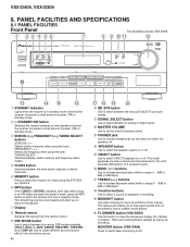
...headphones but this does not switch the speakers off . This feature will enable you to enjoy the broadcast. 7 Display 8 Remote sensor Receives the signals from any stereo source. 56 $% ^ & 0 2 /DTS button Use to switch DIRECT playback on or off . FREQUENCY...AND SPECIFICATIONS 8.1 PANEL FACILITIES Front Panel The illustration shows VSX-D309. 1 23 4 56 7 8 9 0- = N∫m-Û≤?/ Digital Signal Processor R 1 MPX MODE 2/DTS SIGNAL SELECT PHONES MIDNIGHT @ @ ~ !@ # 1 STANDBY indicator Lights when the receiver is weak, press the MPX button to movie soundtracks ...
...headphones but this does not switch the speakers off . This feature will enable you to enjoy the broadcast. 7 Display 8 Remote sensor Receives the signals from any stereo source. 56 $% ^ & 0 2 /DTS button Use to switch DIRECT playback on or off . FREQUENCY...AND SPECIFICATIONS 8.1 PANEL FACILITIES Front Panel The illustration shows VSX-D309. 1 23 4 56 7 8 9 0- = N∫m-Û≤?/ Digital Signal Processor R 1 MPX MODE 2/DTS SIGNAL SELECT PHONES MIDNIGHT @ @ ~ !@ # 1 STANDBY indicator Lights when the receiver is weak, press the MPX button to movie soundtracks ...
Service Manual
Page 57
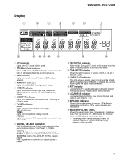
...7 TUNER indicators MONO: Lights when the mono mode is set using . - ANALOG : Lights when an analog signal is being received. OVERLOAD indicator This lights when an analog signal is too strong (the SIGNAL SELECT needs to indicate the type of input signal assigned...VSX-D309 Display 1 2 3 4 5 6 7 PRO LOGIC DSP MIDNIGHT DIGITAL ATT LOUDNESS SIGNAL SELECT ANALOG DIGITAL DIGITAL DTS DIRECT S.BASS MONITOR MONO TUNED SP AB STEREO EON RDS RF ATT dB 8 9 0- = ~ 1 DTS indicator Lights when DTS mode is being used. 2 2 PRO LOGIC indicator When the 2 Surround/DTS mode of the receiver...
...7 TUNER indicators MONO: Lights when the mono mode is set using . - ANALOG : Lights when an analog signal is being received. OVERLOAD indicator This lights when an analog signal is too strong (the SIGNAL SELECT needs to indicate the type of input signal assigned...VSX-D309 Display 1 2 3 4 5 6 7 PRO LOGIC DSP MIDNIGHT DIGITAL ATT LOUDNESS SIGNAL SELECT ANALOG DIGITAL DIGITAL DTS DIRECT S.BASS MONITOR MONO TUNED SP AB STEREO EON RDS RF ATT dB 8 9 0- = ~ 1 DTS indicator Lights when DTS mode is being used. 2 2 PRO LOGIC indicator When the 2 Surround/DTS mode of the receiver...

Service Manual
Page 58
VSX-D409, VSX-D309 Remote Control 1 2 3 4 5 6 7 8 9 0 - Î MULTI CONTROL DVD/LD TV/SAT VCR/DVR CD RECEIVER TUNER CD-R/ TAPE/MD TV CONT 2 DSP MODE MIDNIGHT 5.1CH 1 2 3 4 CHANNEL TEST SELECT TONE 5 6 SIGNAL ATT SELECT 7 8 CHANNEL LEVEL 9 0 EFFECT &#...DISC CH VOL TV CONTROL VOL FQ ST MENU ST ENTER TOP MENU FQ SOURCE CLASS MPX BAND 7 8 3 D.ACCESS 1¡ CHANNEL 4¢ LOUDNESS FUNCTION MUTING RECEIVER FL DIMMER REMOTE SETUP MASTER VOLUME AUDIO/VIDEO PRE-PROGRAMMED REMOTE CONTROL UNIT = ~ ! @ # $ % ^ 1 MULTI CONTROL buttons Use to select the proper...
VSX-D409, VSX-D309 Remote Control 1 2 3 4 5 6 7 8 9 0 - Î MULTI CONTROL DVD/LD TV/SAT VCR/DVR CD RECEIVER TUNER CD-R/ TAPE/MD TV CONT 2 DSP MODE MIDNIGHT 5.1CH 1 2 3 4 CHANNEL TEST SELECT TONE 5 6 SIGNAL ATT SELECT 7 8 CHANNEL LEVEL 9 0 EFFECT &#...DISC CH VOL TV CONTROL VOL FQ ST MENU ST ENTER TOP MENU FQ SOURCE CLASS MPX BAND 7 8 3 D.ACCESS 1¡ CHANNEL 4¢ LOUDNESS FUNCTION MUTING RECEIVER FL DIMMER REMOTE SETUP MASTER VOLUME AUDIO/VIDEO PRE-PROGRAMMED REMOTE CONTROL UNIT = ~ ! @ # $ % ^ 1 MULTI CONTROL buttons Use to select the proper...

Service Manual
Page 59
...8734; ( FQ +/-) & ENTER buttons Use these arrow buttons when setting up the remote control to control other times, for example when teaching the receiver preset codes, with your TV. 5 MENU button Use to adjust the volume on the loudness. If the signal is sent from the remote control ...to add or subtract the amount of station memories. buttons Use to the receiver. VSX-D409, VSX-D309 4 THE FOLLOWING FOUR SETS OF BUTTONS ARE DEDICATED TV CONTROL. buttons Use to access different menus associated with specific meanings. ~...
...8734; ( FQ +/-) & ENTER buttons Use these arrow buttons when setting up the remote control to control other times, for example when teaching the receiver preset codes, with your TV. 5 MENU button Use to adjust the volume on the loudness. If the signal is sent from the remote control ...to add or subtract the amount of station memories. buttons Use to the receiver. VSX-D409, VSX-D309 4 THE FOLLOWING FOUR SETS OF BUTTONS ARE DEDICATED TV CONTROL. buttons Use to access different menus associated with specific meanings. ~...
Service Manual
Page 60
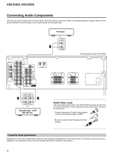
...L CENTER DVD 5.1 CH INPUT COAX OPT PCM/2/DTS DIGITAL IN CD player OUT L R The illustration shows VSX-D309. Be sure to connect the monitor/TV. VSX-D409, VSX-D309 Connecting Audio Components Connect your audio components as shown below. If you experience noise, move the cassette deck... farther away from the transformer in the receiver may occur during playback. Cassette deck placement Depending on ...
...L CENTER DVD 5.1 CH INPUT COAX OPT PCM/2/DTS DIGITAL IN CD player OUT L R The illustration shows VSX-D309. Be sure to connect the monitor/TV. VSX-D409, VSX-D309 Connecting Audio Components Connect your audio components as shown below. If you experience noise, move the cassette deck... farther away from the transformer in the receiver may occur during playback. Cassette deck placement Depending on ...

Service Manual
Page 61
...reserved. AM loop antenna (ATB7009) FM wire antenna (ADH7004) AA size IEC R6P batteries (x2) Î MULTI CONTROL DVD/LD TV/SAT VCR/DVR CD RECEIVER TUNER CD-R/ TAPE/MD TV CONT 2 DSP MODE MIDNIGHT 5.1CH 1 2 3 4 CHANNEL TEST SELECT TONE 5 6 SIGNAL ATT SELECT 7 8 CHANNEL LEVEL 9... of Dolby Laboratories. "Dolby", "Pro Logic" and the double-D symbol are subject to possible modifications without notice, due to improvements. VSX-D409, VSX-D309 8.2 SPECIFICATIONS Amplifier Section Continuous average power output of 60 watts* per channel, min., at 8 ohms, from 40 Hz to ...
...reserved. AM loop antenna (ATB7009) FM wire antenna (ADH7004) AA size IEC R6P batteries (x2) Î MULTI CONTROL DVD/LD TV/SAT VCR/DVR CD RECEIVER TUNER CD-R/ TAPE/MD TV CONT 2 DSP MODE MIDNIGHT 5.1CH 1 2 3 4 CHANNEL TEST SELECT TONE 5 6 SIGNAL ATT SELECT 7 8 CHANNEL LEVEL 9... of Dolby Laboratories. "Dolby", "Pro Logic" and the double-D symbol are subject to possible modifications without notice, due to improvements. VSX-D409, VSX-D309 8.2 SPECIFICATIONS Amplifier Section Continuous average power output of 60 watts* per channel, min., at 8 ohms, from 40 Hz to ...


