

Owners Manual
Page 1
When properly cared for, it will give you for dependability, ease of operation, and operator safety. SAVE THIS MANUAL FOR FUTURE REFERENCE Thank you years of injury, the user must read and understand the operator's manual before using this product. OPERATOR'S MANUAL 6-1/8 in. WARNING: To reduce the risk of rugged, trouble-free performance. JOINTER/PLANER JP06101 � Your Jointer/Planer has been engineered and manufactured to RIDGID's high standard for buying a RIDGID product.
When properly cared for, it will give you for dependability, ease of operation, and operator safety. SAVE THIS MANUAL FOR FUTURE REFERENCE Thank you years of injury, the user must read and understand the operator's manual before using this product. OPERATOR'S MANUAL 6-1/8 in. WARNING: To reduce the risk of rugged, trouble-free performance. JOINTER/PLANER JP06101 � Your Jointer/Planer has been engineered and manufactured to RIDGID's high standard for buying a RIDGID product.

Owners Manual
Page 5
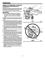
... RABBETING always make cuts in 1/8 in . n ALWAYS USE A STABLE WORK SUPPORT WHEN JOINTING OR PLANING LONG WORKPIECES. n NEVER CUT more than 3/4 in. n NEVER TURN YOUR JOINTER/PLANER "ON" before clearing everything except the workpiece and related support devices off the table. Refer to instruct other users. Your risk from chemically-treated...
... RABBETING always make cuts in 1/8 in . n ALWAYS USE A STABLE WORK SUPPORT WHEN JOINTING OR PLANING LONG WORKPIECES. n NEVER CUT more than 3/4 in. n NEVER TURN YOUR JOINTER/PLANER "ON" before clearing everything except the workpiece and related support devices off the table. Refer to instruct other users. Your risk from chemically-treated...

Owners Manual
Page 9
n Recheck your jointer/planer into a 220-240 volt, 1W5 haitme pB.,lack 3-prong receptacle. ELECTRICAL CHANGING MOTOR VOLTAGE See Figures 2 - 5. n Located on the side of the junction box ... at the back of the motor is connected to change motor voltage from the wire connectors. n Cut off the cover. NOTE: The jointer/planer is properly wired. n Unplug the jointer/planer. UL listed plug. Use the following procedures to a 240 volt, 120V AC power supply through a 240 volt branch circuit havingPower at...
n Recheck your jointer/planer into a 220-240 volt, 1W5 haitme pB.,lack 3-prong receptacle. ELECTRICAL CHANGING MOTOR VOLTAGE See Figures 2 - 5. n Located on the side of the junction box ... at the back of the motor is connected to change motor voltage from the wire connectors. n Cut off the cover. NOTE: The jointer/planer is properly wired. n Unplug the jointer/planer. UL listed plug. Use the following procedures to a 240 volt, 120V AC power supply through a 240 volt branch circuit havingPower at...

Owners Manual
Page 10
...blade does not extend completely through the thickness of a workpiece by the workpiece being dropped into the tool first. Cutter Head (planers and jointer planers) A rotating cutterhead with adjustable blades or knives. Leading End The end of a workpiece usually caused by cutter blades when the ...workpiece is not properly supported. Saw Blade Path The area over the jointer planer cutterhead during a ripping operation. Throw-Back The throwing back of the workpiece pushed into the blade or being kicked back toward ...
...blade does not extend completely through the thickness of a workpiece by the workpiece being dropped into the tool first. Cutter Head (planers and jointer planers) A rotating cutterhead with adjustable blades or knives. Leading End The end of a workpiece usually caused by cutter blades when the ...workpiece is not properly supported. Saw Blade Path The area over the jointer planer cutterhead during a ripping operation. Throw-Back The throwing back of the workpiece pushed into the blade or being kicked back toward ...
Owners Manual
Page 12
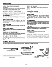
...When the key is inserted in . Easily slides up to use a different (sharper) part of the jointer bed upon which allows the operator to lock infeed or outfeed table at a desired height. It is intended...FENCE STOPS When adjusted properly, these screws to select the depth of a jointer bed which supports the workpiece after a cutting operation. ON/OFF SWITCH Turns the tool on and off.... FEATURES KNOW YOUR JOINTER/PLANER See Figure 6. diameter dust collection hose. Also tool storage for making adjustments or...
...When the key is inserted in . Easily slides up to use a different (sharper) part of the jointer bed upon which allows the operator to lock infeed or outfeed table at a desired height. It is intended...FENCE STOPS When adjusted properly, these screws to select the depth of a jointer bed which supports the workpiece after a cutting operation. ON/OFF SWITCH Turns the tool on and off.... FEATURES KNOW YOUR JOINTER/PLANER See Figure 6. diameter dust collection hose. Also tool storage for making adjustments or...

Owners Manual
Page 13
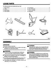
Front Panel 1 8. Rear Panel 1 2 7. Fence Assembly 1 5. Motor and Switch Assembly 1 2. Dust Chute 1 6. Right Side Panel 1 9. LOOSE PARTS The following items are included with your tool: 1. Jointer Bed Assembly 1 3. Left Side Panel 1 Operator's Manual (Not shown) Hardware Blister Pack (Not shown) 4 1 9 8 3 5 7 6 Fig. 8 13 Motor Mount Bracket 1 4.
Front Panel 1 8. Rear Panel 1 2 7. Fence Assembly 1 5. Motor and Switch Assembly 1 2. Dust Chute 1 6. Right Side Panel 1 9. LOOSE PARTS The following items are included with your tool: 1. Jointer Bed Assembly 1 3. Left Side Panel 1 Operator's Manual (Not shown) Hardware Blister Pack (Not shown) 4 1 9 8 3 5 7 6 Fig. 8 13 Motor Mount Bracket 1 4.
Owners Manual
Page 14
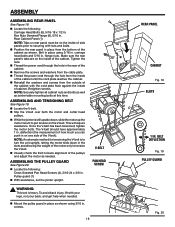
... Guard 1 5. Fig. 9 WARNING: If any parts are damaged or missing, please call 1-866-539-1710 for use with your legs, not your tool: 1. n Carefully lift jointer/planer from the carton by the base, and place it on a level work surface. To avoid back injury, lift with this tool until you have...
... Guard 1 5. Fig. 9 WARNING: If any parts are damaged or missing, please call 1-866-539-1710 for use with your legs, not your tool: 1. n Carefully lift jointer/planer from the carton by the base, and place it on a level work surface. To avoid back injury, lift with this tool until you have...
Owners Manual
Page 16
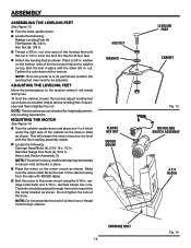
...Bolts (4), 5/16-18 x 1/2 in. washer on the bottom side of the cabinet so the base is tilted as shown. ADJUSTING THE LEVELING FEET Move the jointer/planer to secure nuts and bolts in its permanent location the leveling feet may be adjusted. NOTE: These levelers are not intended for all four... (1) NOTE: This motor is in place. Make sure the motor shaft faces the rear of the leveling feet until the nut is level with RIDGID label). serrated flange hex nuts. HEX NUT WASHER FLANGE HEX NUT MOTOR MOUNT CARRIAGE BOLT 16 LEVELING FOOT CABINET Fig. 13 MOTOR AND SWITCH ASSEMBLY...
...Bolts (4), 5/16-18 x 1/2 in. washer on the bottom side of the cabinet so the base is tilted as shown. ADJUSTING THE LEVELING FEET Move the jointer/planer to secure nuts and bolts in its permanent location the leveling feet may be adjusted. NOTE: These levelers are not intended for all four... (1) NOTE: This motor is in place. Make sure the motor shaft faces the rear of the leveling feet until the nut is level with RIDGID label). serrated flange hex nuts. HEX NUT WASHER FLANGE HEX NUT MOTOR MOUNT CARRIAGE BOLT 16 LEVELING FOOT CABINET Fig. 13 MOTOR AND SWITCH ASSEMBLY...
Owners Manual
Page 17
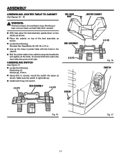
...17 n With help when needed. ASSEMBLING SWITCH See Figure 17. screws, mount the switch into place as shown. n Line up . n Bolt the jointer table to the cabinet using hex head bolts and tighten all the bolts. n Install switch key into dust collection port on left side. n Place ... Using 3/16 in the cabinet. n Locate the following : Switch Key (1) Screws (2), 3/16 in. n Locate the following : Serrated Hex Head Bolts (3), 3/8-16 x 3/4 in jointer table with your legs, not your back, and get help place the bed assembly upside down on top of the bed assembly as shown. Make...
...17 n With help when needed. ASSEMBLING SWITCH See Figure 17. screws, mount the switch into place as shown. n Line up . n Bolt the jointer table to the cabinet using hex head bolts and tighten all the bolts. n Install switch key into dust collection port on left side. n Place ... Using 3/16 in the cabinet. n Locate the following : Switch Key (1) Screws (2), 3/16 in. n Locate the following : Serrated Hex Head Bolts (3), 3/8-16 x 3/4 in jointer table with your legs, not your back, and get help place the bed assembly upside down on top of the bed assembly as shown. Make...
Owners Manual
Page 18
... (the measurement of how much you can push in . Pulley guard (1) n With assistance, set the jointer upright. To avoid back injury, lift with nuts and bolts. n While the jointer is still upside down in . ASSEMBLING THE PULLEY GUARD See Figure 20. screws. n Locate the following ... V-belt. This will require assistance. Once the V-belt has been tensioned, tighten the motor bolts. The V-belt should have approximately 1 in place as jointer table mounting bolts at this time. NOTE: An alternate method for tensioning the V-belt is heavy. n Locate the following : Carriage Head Bolts (6), 5/...
... (the measurement of how much you can push in . Pulley guard (1) n With assistance, set the jointer upright. To avoid back injury, lift with nuts and bolts. n While the jointer is still upside down in . ASSEMBLING THE PULLEY GUARD See Figure 20. screws. n Locate the following ... V-belt. This will require assistance. Once the V-belt has been tensioned, tighten the motor bolts. The V-belt should have approximately 1 in place as jointer table mounting bolts at this time. NOTE: An alternate method for tensioning the V-belt is heavy. n Locate the following : Carriage Head Bolts (6), 5/...

Owners Manual
Page 19
.... FENCE MOUNT n Thread the fence tilt knob into the slot just below the chute on the fence mount. Fasten the dust chute on with the jointer) used for knife adjustments, can be positioned upwards so they fit in place, slide the fence lock knob through the fence assembly and fence mount...
.... FENCE MOUNT n Thread the fence tilt knob into the slot just below the chute on the fence mount. Fasten the dust chute on with the jointer) used for knife adjustments, can be positioned upwards so they fit in place, slide the fence lock knob through the fence assembly and fence mount...

Owners Manual
Page 21
... be ready to resist kickback should it is used to a full and complete stop. Store key in the OFF ( O ) position. BEFORE LEAVING THE JOINTER/PLANER n Place the switch in a safe place. n Lock the shop. WARNING: Always wear safety goggles or safety glasses with the cutter head. n ...is intended to be used on wood only n �Jointing/Planing n �Rabbeting n �Beveling/Chamfering BASIC OPERATION OF THE JOINTER/PLANER The jointer/planer allows the operator to make the depth of an inch for best results in line with side shields when operating tools. n When...
... be ready to resist kickback should it is used to a full and complete stop. Store key in the OFF ( O ) position. BEFORE LEAVING THE JOINTER/PLANER n Place the switch in a safe place. n Lock the shop. WARNING: Always wear safety goggles or safety glasses with the cutter head. n ...is intended to be used on wood only n �Jointing/Planing n �Rabbeting n �Beveling/Chamfering BASIC OPERATION OF THE JOINTER/PLANER The jointer/planer allows the operator to make the depth of an inch for best results in line with side shields when operating tools. n When...
Owners Manual
Page 24
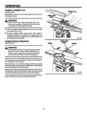
... 1/16 in any parts. When necessary to feed the wood, do so could result in kickback of workpiece and could cause a "snipe" on the jointer/planer, workpiece, or push block/push stick. When using only one push stick/ push block to feed against fence. n Feed the board at a ... depth of cut to kickback. Make sure the clamps and locks are tight. n Feed with and without the push blocks before turning the jointer/planer on workpiece and keep workpiece pressed firmly against grain, take very light cuts and feed slowly to minimize workpiece splintering, breakage or dangerous ...
... 1/16 in any parts. When necessary to feed the wood, do so could result in kickback of workpiece and could cause a "snipe" on the jointer/planer, workpiece, or push block/push stick. When using only one push stick/ push block to feed against fence. n Feed the board at a ... depth of cut to kickback. Make sure the clamps and locks are tight. n Feed with and without the push blocks before turning the jointer/planer on workpiece and keep workpiece pressed firmly against grain, take very light cuts and feed slowly to minimize workpiece splintering, breakage or dangerous ...
Owners Manual
Page 25
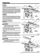
... result in serious personal injury. � PLANING Fig. 32 � JOINTING BEVELING Fig. 33 � 25 Fig. 34 OPERATION PLANING See Figure 32. Planing on a jointer will not necessarily make it flat and smooth. Jointing is the removal of wood along the edge of a piece of wood so as to make... to desired angle. Planing is removing the corner or the edge of a board so as to be performed first. NOTE: Removing only the corner on a jointer only smooths and flattens.
... result in serious personal injury. � PLANING Fig. 32 � JOINTING BEVELING Fig. 33 � 25 Fig. 34 OPERATION PLANING See Figure 32. Planing on a jointer will not necessarily make it flat and smooth. Jointing is the removal of wood along the edge of a piece of wood so as to make... to desired angle. Planing is removing the corner or the edge of a board so as to be performed first. NOTE: Removing only the corner on a jointer only smooths and flattens.
Owners Manual
Page 28
... . WARNING: Moving parts can be moved toward the guard where the knives are new or freshly sharpened the fence should be moved across the jointer/planer to heed this position. As the knives become dull, the fence can injure. n Hold the workpiece firmly against the fence. Failure to... the desired position. To move the fence, turn jointer/planer off and wait for all parts to the extreme rear of outfeed and infeed tables but not beyond the end of the knives. OPERATION...
... . WARNING: Moving parts can be moved toward the guard where the knives are new or freshly sharpened the fence should be moved across the jointer/planer to heed this position. As the knives become dull, the fence can injure. n Hold the workpiece firmly against the fence. Failure to... the desired position. To move the fence, turn jointer/planer off and wait for all parts to the extreme rear of outfeed and infeed tables but not beyond the end of the knives. OPERATION...
Owners Manual
Page 29
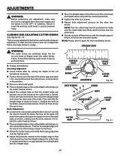
... the cutter head as the cutter head is rotated and there is turned. Position the straight edge over the end of one of the jointer, approximately 1/4 in serious personal injury. n Move the straight edge to the other two knives. n Tighten the knife lock screws. Failure.... OUTFEED TABLE LOCK SCREW WEDGE KNIFE JACKSCREW INFEED TABLE CUTTER HEAD Fig. 40 LOCK SCREWS WEDGE KNIFE JACKSCREWS CUTTER HEAD 1/16 IN. n Unplug jointer/planer. Checking Alignment: n Lower infeed table by turning the depth of the cutter knives. n Position the fence to realign. n Adjust the ...
... the cutter head as the cutter head is rotated and there is turned. Position the straight edge over the end of one of the jointer, approximately 1/4 in serious personal injury. n Move the straight edge to the other two knives. n Tighten the knife lock screws. Failure.... OUTFEED TABLE LOCK SCREW WEDGE KNIFE JACKSCREW INFEED TABLE CUTTER HEAD Fig. 40 LOCK SCREWS WEDGE KNIFE JACKSCREWS CUTTER HEAD 1/16 IN. n Unplug jointer/planer. Checking Alignment: n Lower infeed table by turning the depth of the cutter knives. n Position the fence to realign. n Adjust the ...
Owners Manual
Page 30
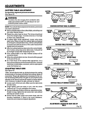
... the outfeed table is adjusted at their highest point of the cutter head at the factory and should not require adjustment. The gibs on your jointer. If table is too much resistance, loosen the set at the factory and should not be gouged at either end, readjust knife. If there ... locks are provided to power source outlet. n Recheck table play between the mating dovetail ways of the base and infeed and outfeed tables of the jointer. n If outfeed table needs adjustment, loosen wing screw table locks. It should require no open space under the finished cut . n As a final check of ...
... the outfeed table is adjusted at their highest point of the cutter head at the factory and should not require adjustment. The gibs on your jointer. If table is too much resistance, loosen the set at the factory and should not be gouged at either end, readjust knife. If there ... locks are provided to power source outlet. n Recheck table play between the mating dovetail ways of the base and infeed and outfeed tables of the jointer. n If outfeed table needs adjustment, loosen wing screw table locks. It should require no open space under the finished cut . n As a final check of ...
Owners Manual
Page 31
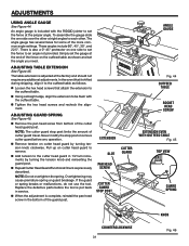
... OF CUT KNOB COUNTERCLOCKWISE 31 Fig. 46 ADJUSTMENTS USING ANGLE GAUGE See Figure 44. n Using a straight edge, align the extension to be flush with the RIDGID jointer to the outfeed table. ADJUSTING GUARD SPRING See Figure 46. n Remove tension on the outfeed table as previously described. To assemble the gauge slide the...
... OF CUT KNOB COUNTERCLOCKWISE 31 Fig. 46 ADJUSTMENTS USING ANGLE GAUGE See Figure 44. n Using a straight edge, align the extension to be flush with the RIDGID jointer to the outfeed table. ADJUSTING GUARD SPRING See Figure 46. n Remove tension on the outfeed table as previously described. To assemble the gauge slide the...
Owners Manual
Page 32
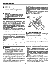
...the "Motor Troubleshooting Chart." NOTE: The speed of sawdust and wood chips and should only be done by their use only identical RIDGID replacement parts. n Connect this motor should be traced to loose or incorrect connections, overload, low voltage (such as small size wire...also deters rusting. n Fuses may "blow" or circuit breakers may be regulated or changed. Electric tools used . If improper or dull jointer knives are used on woodworking tools are highly abrasive to the accumulation of this may create a hazard or cause product damage. Motors used on...
...the "Motor Troubleshooting Chart." NOTE: The speed of sawdust and wood chips and should only be done by their use only identical RIDGID replacement parts. n Connect this motor should be traced to loose or incorrect connections, overload, low voltage (such as small size wire...also deters rusting. n Fuses may "blow" or circuit breakers may be regulated or changed. Electric tools used . If improper or dull jointer knives are used on woodworking tools are highly abrasive to the accumulation of this may create a hazard or cause product damage. Motors used on...
Owners Manual
Page 34
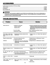
... high above outfeed table, or they are listed above 1. Outfeed table set higher than other 2. ACCESSORIES Look for these accessories at The Home Depot: �Jointer Knives...AC8600 Push Blocks ...AC8601 Dust Collection Kit...AC8602 WARNING: Attachments and accessories available for use of attachments or accessories not recommended can result in...
... high above outfeed table, or they are listed above 1. Outfeed table set higher than other 2. ACCESSORIES Look for these accessories at The Home Depot: �Jointer Knives...AC8600 Push Blocks ...AC8601 Dust Collection Kit...AC8602 WARNING: Attachments and accessories available for use of attachments or accessories not recommended can result in...