

Owners Manual
Page 1
JOINTER/PLANER JP06101 � Your Jointer/Planer has been engineered and manufactured to RIDGID's high standard for buying a RIDGID product. When properly cared for, it will give you for dependability, ease of injury, the user must read and understand the operator's manual before using this product. SAVE THIS MANUAL FOR FUTURE REFERENCE OPERATOR'S MANUAL 6-1/8 in. Thank you years of rugged, trouble-free performance. WARNING: To reduce the risk of operation, and operator safety.
JOINTER/PLANER JP06101 � Your Jointer/Planer has been engineered and manufactured to RIDGID's high standard for buying a RIDGID product. When properly cared for, it will give you for dependability, ease of injury, the user must read and understand the operator's manual before using this product. SAVE THIS MANUAL FOR FUTURE REFERENCE OPERATOR'S MANUAL 6-1/8 in. Thank you years of rugged, trouble-free performance. WARNING: To reduce the risk of operation, and operator safety.

Owners Manual
Page 2
TABLE OF CONTENTS n Introduction...2 n General Safety Rules ...3-4 n Specific Safety Rules...5 n Symbols...6-7 n Electrical ...8-9 n Glossary of this product making its use more pleasant and enjoyable. Safety, performance, and dependability have been given top priority in the design of Terms ...10 n Features ...11-12 n Tools Needed...12 n ...
TABLE OF CONTENTS n Introduction...2 n General Safety Rules ...3-4 n Specific Safety Rules...5 n Symbols...6-7 n Electrical ...8-9 n Glossary of this product making its use more pleasant and enjoyable. Safety, performance, and dependability have been given top priority in the design of Terms ...10 n Features ...11-12 n Tools Needed...12 n ...

Owners Manual
Page 3
...sparking of moving parts. The conductor with insulation having an outer surface that is necessary, do a job for which it is used outdoors, use of improper accessories may result in loss of parts, mounting and any tool. GENERAL SAFETY RULES WARNING: Read and understand all...spindle only. n AVOID ACCIDENTAL STARTING. n NEVER STAND ON TOOL. TURN THE POWER OFF. Cluttered work areas and work area well lit. Use clamps or a vise to disconnect from power source. READ ALL INSTRUCTIONS n KNOW YOUR POWER TOOL. Read the operator's manual carefully. A ...
...sparking of moving parts. The conductor with insulation having an outer surface that is necessary, do a job for which it is used outdoors, use of improper accessories may result in loss of parts, mounting and any tool. GENERAL SAFETY RULES WARNING: Read and understand all...spindle only. n AVOID ACCIDENTAL STARTING. n NEVER STAND ON TOOL. TURN THE POWER OFF. Cluttered work areas and work area well lit. Use clamps or a vise to disconnect from power source. READ ALL INSTRUCTIONS n KNOW YOUR POWER TOOL. Read the operator's manual carefully. A ...

Owners Manual
Page 4
...n DO NOT OPERATE A TOOL WHILE UNDER THE INFLUENCE OF DRUGS, ALCOHOL, OR ANY MEDICATION. n INSPECT FOR AND REMOVE ALL NAILS FROM LUMBER BEFORE USING THIS TOOL. n NEVER START A TOOL WHEN ANY ROTATING COMPONENT IS IN CONTACT WITH THE WORKPIECE. Make sure the spindle or sanding belt assembly is... tight and not making contact with the accessory. n USE ONLY RECOMMENDED ACCESSORIES listed in this rule will reduce the risk of accessories are not listed may create a hazard or cause product damage. n...
...n DO NOT OPERATE A TOOL WHILE UNDER THE INFLUENCE OF DRUGS, ALCOHOL, OR ANY MEDICATION. n INSPECT FOR AND REMOVE ALL NAILS FROM LUMBER BEFORE USING THIS TOOL. n NEVER START A TOOL WHEN ANY ROTATING COMPONENT IS IN CONTACT WITH THE WORKPIECE. Make sure the spindle or sanding belt assembly is... tight and not making contact with the accessory. n USE ONLY RECOMMENDED ACCESSORIES listed in this rule will reduce the risk of accessories are not listed may create a hazard or cause product damage. n...

Owners Manual
Page 5
..., sawing, grinding, drilling, and other construction activities contains chemicals known to instruct other reproductive harm. n PROTECT YOUR HEARING. Never use to cause cancer, birth defects or other users. n AVOID AWKWARD OPERATIONS AND HAND POSITIONS where a sudden slip could cause your exposure... SURE THERE'S NO DEBRIS between the workpiece and either hand over the cutter head during extended periods of serious personal injury. n ALWAYS USE PUSH BLOCKS/PUSH STICK when planing. n NEVER perform any operation. Wear a face or dust mask if the cutting operation is dusty....
..., sawing, grinding, drilling, and other construction activities contains chemicals known to instruct other reproductive harm. n PROTECT YOUR HEARING. Never use to cause cancer, birth defects or other users. n AVOID AWKWARD OPERATIONS AND HAND POSITIONS where a sudden slip could cause your exposure... SURE THERE'S NO DEBRIS between the workpiece and either hand over the cutter head during extended periods of serious personal injury. n ALWAYS USE PUSH BLOCKS/PUSH STICK when planing. n NEVER perform any operation. Wear a face or dust mask if the cutting operation is dusty....

Owners Manual
Page 6
Read The Operator's Manual To reduce the risk of injury, user must read and understand operator's manual before using this tool. Hot Surface To reduce the risk of injury or damage, avoid contact with side shields and a full face shield when operating...safety glasses with any hot surface. 6 Failure to keep your hands away from the blade will result in serious personal injury. Failure to rain or use in serious personal injury. Please study them and learn their meaning. SYMBOL NAME DESIGNATION/EXPLANATION V Volts Voltage A Amperes Current Hz Hertz Frequency (cycles...
Read The Operator's Manual To reduce the risk of injury, user must read and understand operator's manual before using this tool. Hot Surface To reduce the risk of injury or damage, avoid contact with side shields and a full face shield when operating...safety glasses with any hot surface. 6 Failure to keep your hands away from the blade will result in serious personal injury. Failure to rain or use in serious personal injury. Please study them and learn their meaning. SYMBOL NAME DESIGNATION/EXPLANATION V Volts Voltage A Amperes Current Hz Hertz Frequency (cycles...

Owners Manual
Page 7
.... SERVICE Servicing requires extreme care and knowledge and should be performed only by a qualified service technician. When servicing, use this operator's manual and review frequently for continuing safe operation and instructing others who may result in death or serious injury... repair. Indicates a potentially hazardous situation, which can result in foreign objects being thrown into your nearest AUTHORIZED SERVICE CENTER for use this product. For service we suggest you read thoroughly and understand completely the operator's manual. Indicates a potentially hazardous situation,...
.... SERVICE Servicing requires extreme care and knowledge and should be performed only by a qualified service technician. When servicing, use this operator's manual and review frequently for continuing safe operation and instructing others who may result in death or serious injury... repair. Indicates a potentially hazardous situation, which can result in foreign objects being thrown into your nearest AUTHORIZED SERVICE CENTER for use this product. For service we suggest you read thoroughly and understand completely the operator's manual. Indicates a potentially hazardous situation,...

Owners Manual
Page 8
... or service personnel if the grounding instructions are working area. Check with insulation having an equipment-groundIng conductor and a grounding plug. Never use . Position the cord so that is approximately 3,450/min. This speed is necessary, do so can result in a loss of power... touching the damaged area could cause electrical shock resulting in serious injury. WARNING: Keep the extension cord clear of least resistance for use on lumber, tools or other obstructions while you are not completely understood, or if in figure 1. Improper connection of the electric...
... or service personnel if the grounding instructions are working area. Check with insulation having an equipment-groundIng conductor and a grounding plug. Never use . Position the cord so that is approximately 3,450/min. This speed is necessary, do so can result in a loss of power... touching the damaged area could cause electrical shock resulting in serious injury. WARNING: Keep the extension cord clear of least resistance for use on lumber, tools or other obstructions while you are not completely understood, or if in figure 1. Improper connection of the electric...

Owners Manual
Page 9
... Junction Box 3 5 2 1 48 Fig. 3 Black White Green Wire Nut 240V Power Cord 240V Wiring Motor Junction Box Motor Junction FBOoRx USE WITH 220-240 VOLT Fig. 4 1 35 2 48 3 JUNCTION B25OX 1 48 White Black Green 120V Power Cord 120V Wiring FOR... kill. n Unplug the jointer/planer. n Reinstall the wire connectors and wrap each wire with the wiring diagrams. n Reinstall the junction box cover using thMeotpohr Jilulinpcstion Box screw. Remove wire connectors. Green n Make certain the receptacle is properly wired. n Located on the side of serious personal injury,...
... Junction Box 3 5 2 1 48 Fig. 3 Black White Green Wire Nut 240V Power Cord 240V Wiring Motor Junction Box Motor Junction FBOoRx USE WITH 220-240 VOLT Fig. 4 1 35 2 48 3 JUNCTION B25OX 1 48 White Black Green 120V Power Cord 120V Wiring FOR... kill. n Unplug the jointer/planer. n Reinstall the wire connectors and wrap each wire with the wiring diagrams. n Reinstall the junction box cover using thMeotpohr Jilulinpcstion Box screw. Remove wire connectors. Green n Make certain the receptacle is properly wired. n Located on the side of serious personal injury,...

Owners Manual
Page 10
...knives remove material from wood products. Gum A sticky, sap-based residue from the workpiece. Push Blocks and Push Sticks (for table saws) Devices used for narrow ripping operations. Revolutions Per Minute (RPM) The number of the saw during cutting operations. Snipe (planers) Depression made at 90°... by the workpiece being dropped into the blade or being guided by guiding it applies to the workpiece, that area which will be used to feed the workpiece through the thickness of the workpiece pushed into the tool first. Kickback A hazard that serves as a guide for...
...knives remove material from wood products. Gum A sticky, sap-based residue from the workpiece. Push Blocks and Push Sticks (for table saws) Devices used for narrow ripping operations. Revolutions Per Minute (RPM) The number of the saw during cutting operations. Snipe (planers) Depression made at 90°... by the workpiece being dropped into the blade or being guided by guiding it applies to the workpiece, that area which will be used to feed the workpiece through the thickness of the workpiece pushed into the tool first. Kickback A hazard that serves as a guide for...
Owners Manual
Page 12
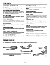
... installing the knives: PHILLIPS SCREWDRIVER STRAIGHT EDGE ADJUSTABLE WRENCH OPEN END WRENCH (1/2 IN.) COMBINATION SQUARE Fig. 7 12 TABLE LOCK SCREW Use these stops provide a method for quickly moving the fence to lower infeed table in 1/8 in . DEPTH OF CUT HANDWHEEL By turning...workpiece after a cutting operation. Before attempting to 1/2 in . BEVEL LOCK HANDLE Secures the fence at a desired height. ANGLE GAUGE Used to use this product, familiarize yourself with all operating Features and Safety Rules. This is spring loaded so it automatically keeps the cutter head ...
... installing the knives: PHILLIPS SCREWDRIVER STRAIGHT EDGE ADJUSTABLE WRENCH OPEN END WRENCH (1/2 IN.) COMBINATION SQUARE Fig. 7 12 TABLE LOCK SCREW Use these stops provide a method for quickly moving the fence to lower infeed table in 1/8 in . DEPTH OF CUT HANDWHEEL By turning...workpiece after a cutting operation. Before attempting to 1/2 in . BEVEL LOCK HANDLE Secures the fence at a desired height. ANGLE GAUGE Used to use this product, familiarize yourself with all operating Features and Safety Rules. This is spring loaded so it automatically keeps the cutter head ...
Owners Manual
Page 14
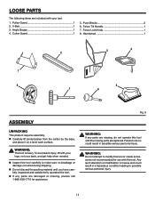
... tool. V-Belt 1 3. Fence Tilt Handle 1 7. n Do not discard the packing material until the missing parts are damaged or missing, please call 1-866-539-1710 for use with this tool until you have carefully inspected and satisfactorily operated the tool. Fig. 9 WARNING: If any parts are replaced. n Carefully lift jointer/planer from...
... tool. V-Belt 1 3. Fence Tilt Handle 1 7. n Do not discard the packing material until the missing parts are damaged or missing, please call 1-866-539-1710 for use with this tool until you have carefully inspected and satisfactorily operated the tool. Fig. 9 WARNING: If any parts are replaced. n Carefully lift jointer/planer from...

Owners Manual
Page 15
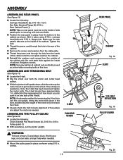
...: Make sure that the tabs of the left side panel. carriage head bolts and 5/16 in . The rear panel will be easier to the panel using the 5/16 in . Left Panel Side (1) Right Panel Side (1) Motor Mount (1) n Mount the motor mount onto the left and right side panels as shown.... complete. Tighten the nuts with a wrench. n Locate the following : Carriage Head Bolts (6), 5/16-18 x 1/2 in . carriage head bolts and 5/16 in . Front panel with RIDGID logo (1) NOTE: Tabs on front panel must be on the inside of the left side panel as the switch opening. carriage head bolts and 5/16...
...: Make sure that the tabs of the left side panel. carriage head bolts and 5/16 in . The rear panel will be easier to the panel using the 5/16 in . Left Panel Side (1) Right Panel Side (1) Motor Mount (1) n Mount the motor mount onto the left and right side panels as shown.... complete. Tighten the nuts with a wrench. n Locate the following : Carriage Head Bolts (6), 5/16-18 x 1/2 in . carriage head bolts and 5/16 in . Front panel with RIDGID logo (1) NOTE: Tabs on front panel must be on the inside of the left side panel as the switch opening. carriage head bolts and 5/16...
Owners Manual
Page 16
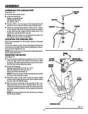
... is in place with the floor making assembly easier. To level the cabinet, loosen the nut and adjust leveling feet up or down with RIDGID label). MOUNTING THE MOTOR See Figure 14. Do not tighten the nuts at this time. HEX NUT WASHER FLANGE HEX NUT MOTOR MOUNT CARRIAGE...: These levelers are not intended for all four leveling feet if necessary and then retighten the nut. additional help may need to the motor mount using the 5/16 in . n Locate the following : Rubber Leveling Feet (4) Flat Washer (8), 3/8 in . carriage head bolts and 5/16 in . NOTE: Do not assemble the...
... is in place with the floor making assembly easier. To level the cabinet, loosen the nut and adjust leveling feet up or down with RIDGID label). MOUNTING THE MOTOR See Figure 14. Do not tighten the nuts at this time. HEX NUT WASHER FLANGE HEX NUT MOTOR MOUNT CARRIAGE...: These levelers are not intended for all four leveling feet if necessary and then retighten the nut. additional help may need to the motor mount using the 5/16 in . n Locate the following : Rubber Leveling Feet (4) Flat Washer (8), 3/8 in . carriage head bolts and 5/16 in . NOTE: Do not assemble the...
Owners Manual
Page 17
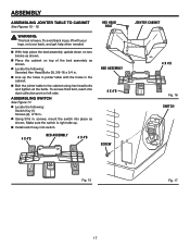
... n Locate the following : Switch Key (1) Screws (2), 3/16 in the cabinet. To access third bolt, reach into dust collection port on two blocks as shown. n Using 3/16 in . WARNING: This tool is right side up the holes in jointer table with your legs, not your back, and get help place the...assembly upside down on left side. To avoid back injury, lift with the holes in . n Line up . n Bolt the jointer table to the cabinet using hex head bolts and tighten all the bolts. ASSEMBLING SWITCH See Figure 17. n Install switch key into place as shown. n With help when needed. ...
... n Locate the following : Switch Key (1) Screws (2), 3/16 in the cabinet. To access third bolt, reach into dust collection port on two blocks as shown. n Using 3/16 in . WARNING: This tool is right side up the holes in jointer table with your legs, not your back, and get help place the...assembly upside down on left side. To avoid back injury, lift with the holes in . n Line up . n Bolt the jointer table to the cabinet using hex head bolts and tighten all the bolts. ASSEMBLING SWITCH See Figure 17. n Install switch key into place as shown. n With help when needed. ...
Owners Manual
Page 18
...Reinstall the washers and screws from the bottom of cabinet. ASSEMBLING THE PULLEY GUARD See Figure 20. n Position the rear panel in . Bolt in place using 3/16 in place from the outside of the cabinet with your legs, not your back, and get help when needed . n Thread the power cord through... the hole in . NOTE: Securely tighten all cabinet nuts and bolts as well as shown using 5/16 in the rear of the cabinet until the cord plate reaches the cabinet. ASSEMBLING AND TENSIONING BELT See Figure 19. NOTE: An alternate method...
...Reinstall the washers and screws from the bottom of cabinet. ASSEMBLING THE PULLEY GUARD See Figure 20. n Position the rear panel in . Bolt in place using 3/16 in place from the outside of the cabinet with your legs, not your back, and get help when needed . n Thread the power cord through... the hole in . NOTE: Securely tighten all cabinet nuts and bolts as well as shown using 5/16 in the rear of the cabinet until the cord plate reaches the cabinet. ASSEMBLING AND TENSIONING BELT See Figure 19. NOTE: An alternate method...

Owners Manual
Page 19
... just below the chute on the fence mount. ASSEMBLING DUST CHUTE See Figure 22. n The hex key and open end wrench (supplied with the jointer) used for knife adjustments, can be positioned upwards so they fit in the table. T-Nut (1) Fence Assembly (1) Fence Lock Knob (1) Fence Tilt Knob (1) NOTE: While ... of the dust chute. Then lock in fence assembly lines up and retighten the wing screws. Make sure the tabs on the nut sit in use, simply loosen the wing screws, lift the bottom of the base. FENCE ASSEMBLY NOTE: While installing fence to make sure it moves freely. n Once ...
... just below the chute on the fence mount. ASSEMBLING DUST CHUTE See Figure 22. n The hex key and open end wrench (supplied with the jointer) used for knife adjustments, can be positioned upwards so they fit in the table. T-Nut (1) Fence Assembly (1) Fence Lock Knob (1) Fence Tilt Knob (1) NOTE: While ... of the dust chute. Then lock in fence assembly lines up and retighten the wing screws. Make sure the tabs on the nut sit in use, simply loosen the wing screws, lift the bottom of the base. FENCE ASSEMBLY NOTE: While installing fence to make sure it moves freely. n Once ...

Owners Manual
Page 21
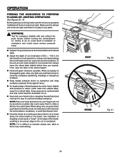
... possible spaces between 1/32 and 1/16 of lumber. CAUSES OF KICKBACK Kickback can cause the wood to be sure you careless. AVOIDING KICKBACK n Use push blocks or push sticks whenever possible. Never force cuts. n To turn the saw OFF ( O ), press the switch button down. BEFORE...planer from the workpiece and may contact the cutter head. APPLICATIONS You may be joined edge to make cuts with the cutter head. n Always use steady, even pressure. n Lock the shop. OPERATION WARNING: Do not allow familiarity with side shields when operating tools. Keep your eyes, ...
... possible spaces between 1/32 and 1/16 of lumber. CAUSES OF KICKBACK Kickback can cause the wood to be sure you careless. AVOIDING KICKBACK n Use push blocks or push sticks whenever possible. Never force cuts. n To turn the saw OFF ( O ), press the switch button down. BEFORE...planer from the workpiece and may contact the cutter head. APPLICATIONS You may be joined edge to make cuts with the cutter head. n Always use steady, even pressure. n Lock the shop. OPERATION WARNING: Do not allow familiarity with side shields when operating tools. Keep your eyes, ...

Owners Manual
Page 22
... maintain contact with sandpaper. A push block has a handle fastened by recessed screws from sliding or slipping on the top face of a kickback. USING THE PUSH BLOCKS/PUSH STICKS See Figure 27. CAUTION: Before turning switch "ON," make sure the cutter guard is correctly installed and operating properly and...under the cutter guard and could be made in various sizes and shapes from scrap wood to prevent push block/push stick from the underside. Use a hand-over-hand motion of the push blocks to heed this warning could result in . WARNING: To prevent ant tendency of the ...
... maintain contact with sandpaper. A push block has a handle fastened by recessed screws from sliding or slipping on the top face of a kickback. USING THE PUSH BLOCKS/PUSH STICKS See Figure 27. CAUTION: Before turning switch "ON," make sure the cutter guard is correctly installed and operating properly and...under the cutter guard and could be made in various sizes and shapes from scrap wood to prevent push block/push stick from the underside. Use a hand-over-hand motion of the push blocks to heed this warning could result in . WARNING: To prevent ant tendency of the ...
Owners Manual
Page 24
... possible. A deep cut is no play in kickback of cut is difficult to do not put your fingers will not be sure you wanted. When using only one push stick/ push block to slide or fall into the cutter head. n Support long workpieces at outfeed table and near cutter head for... edge as the cut makes feeding the wood harder and can cause the wood to continue feeding workpiece. NOTE: If it to rear, to kickback. n Use hand-over-hand motion, releasing forward hand and moving it is made along the entire length of cut you planned, always lower the infeed table...
... possible. A deep cut is no play in kickback of cut is difficult to do not put your fingers will not be sure you wanted. When using only one push stick/ push block to slide or fall into the cutter head. n Support long workpieces at outfeed table and near cutter head for... edge as the cut makes feeding the wood harder and can cause the wood to continue feeding workpiece. NOTE: If it to rear, to kickback. n Use hand-over-hand motion, releasing forward hand and moving it is made along the entire length of cut you planned, always lower the infeed table...
