
Owners Manual
Page 2
......2 General Safety Rules...3-4 Specific Safety Rules...5 Symbols...6 Electrical...7-8 Features...9-10 Tools Needed...10 Loose Parts...11 Assembly...12-20 Operation...21-25 Adjustments...26-27 Maintenance...27-28 Warranty...29 Parts Ordering and Service...Back page INTRODUCTION This product has many features for making it easy to maintain and operate. 2 - Safety, performance, and...
......2 General Safety Rules...3-4 Specific Safety Rules...5 Symbols...6 Electrical...7-8 Features...9-10 Tools Needed...10 Loose Parts...11 Assembly...12-20 Operation...21-25 Adjustments...26-27 Maintenance...27-28 Warranty...29 Parts Ordering and Service...Back page INTRODUCTION This product has many features for making it easy to maintain and operate. 2 - Safety, performance, and...

Owners Manual
Page 3
... ACCIDENTAL STARTING. Use only a cord heavy enough to rain. A guard or other part that is in loss of operation. DO NOT ABUSE CORD. Wear hearing protection during extended periods of power and overheating. READ ALL INSTRUCTIONS KNOW YOUR POWER TOOL. Don't force the tool or attachment to avoid risk of parts, mounting and any tool. USE RECOMMENDED ACCESSORIES. Make sure your hand and frees both hands to...
... ACCIDENTAL STARTING. Use only a cord heavy enough to rain. A guard or other part that is in loss of operation. DO NOT ABUSE CORD. Wear hearing protection during extended periods of power and overheating. READ ALL INSTRUCTIONS KNOW YOUR POWER TOOL. Don't force the tool or attachment to avoid risk of parts, mounting and any tool. USE RECOMMENDED ACCESSORIES. Make sure your hand and frees both hands to...
Owners Manual
Page 4
... grounding instructions are not completely understood or if in this manual or addendums. Use of accessories that accept the tool's plug. DO NOT MODIFY the plug provided. English Never use washers or arbor nuts that have repaired by an authorized service center. USE ONLY CORRECT WHEELs. Do not attempt to power supply. 4 - Use of any solvents to a live terminal. Have defective switches replaced by a qualified service...
... grounding instructions are not completely understood or if in this manual or addendums. Use of accessories that accept the tool's plug. DO NOT MODIFY the plug provided. English Never use washers or arbor nuts that have repaired by an authorized service center. USE ONLY CORRECT WHEELs. Do not attempt to power supply. 4 - Use of any solvents to a live terminal. Have defective switches replaced by a qualified service...

Owners Manual
Page 5
... reproductive harm. e) Replace damaged cutting wheel before servicing, when changing cutting wheels, and cleaning. SPECIFIC SAFETY RULES SECURE work firmly against the miter guide or fence. NEVER stand or have the following markings: a) Wear eye, hearing, and breathing protection. f) Do not fill water bath above water fill line. SAVE THESE INSTRUCTIONS. If you do this tool, loan them frequently and use to filter...
... reproductive harm. e) Replace damaged cutting wheel before servicing, when changing cutting wheels, and cleaning. SPECIFIC SAFETY RULES SECURE work firmly against the miter guide or fence. NEVER stand or have the following markings: a) Wear eye, hearing, and breathing protection. f) Do not fill water bath above water fill line. SAVE THESE INSTRUCTIONS. If you do this tool, loan them frequently and use to filter...

Owners Manual
Page 7
... all local codes and ordinances. Repair or replace a damaged or worn cord immediately. ELECTRICAL Extension Cords Use only 3-wire extension cords that have the proper outlet installed by a precision built electric motor. WARNING: Check extension cords before each use ". It should be too light for outside use an extension cord heavy enough to reduce the risk of this tool on the cord's jacket. SPEED AND WIRING The no-load speed of electric shock. If...
... all local codes and ordinances. Repair or replace a damaged or worn cord immediately. ELECTRICAL Extension Cords Use only 3-wire extension cords that have the proper outlet installed by a precision built electric motor. WARNING: Check extension cords before each use ". It should be too light for outside use an extension cord heavy enough to reduce the risk of this tool on the cord's jacket. SPEED AND WIRING The no-load speed of electric shock. If...

Owners Manual
Page 10
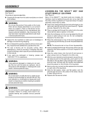
... from cracking. The sliding table allows the user to scale) are attempting. Turn the diverter valve to the right and use of this product, familiarize yourself with your saw head at 0°, 22.5°, and 45°. LED WORKLIGHT - ON/OFF SWITCH - TOOLS NEEDED The following tools (not included or drawn to slide the workpiece into the cutting wheel for trouble-free cutting. English ADJUSTABLE WRENCH 10 mm WRENCH Fig. 4 Rinse...
... from cracking. The sliding table allows the user to scale) are attempting. Turn the diverter valve to the right and use of this product, familiarize yourself with your saw head at 0°, 22.5°, and 45°. LED WORKLIGHT - ON/OFF SWITCH - TOOLS NEEDED The following tools (not included or drawn to slide the workpiece into the cutting wheel for trouble-free cutting. English ADJUSTABLE WRENCH 10 mm WRENCH Fig. 4 Rinse...
Owners Manual
Page 11
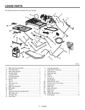
... leg assembly 1 G - Wheel 2 O - Left outer tube 1 V - Wheel wrench, 6 mm 1 BB - Water tray 1 HH - Motor head assembly 1 D - Cap bolt (short 2 E - Cap bolt (long 4 H - Hex nut 4 J - Water tray extensions 2 M - Lower brace 1 S - Hex head bolt 2 AA - Sliding table extension 1 II - Hose clamps 12 11 - English Lock nut 8 Y - Span-deck clamp 1 FF - Sleeve 2 I HH GG FF EE DD CC U J l K X Y V W AA BB L C E F D HG m o n p q z r t S ii Fig. 5 A - Spacer 8 X - Water pump 1 GG - Long tube assembly...
... leg assembly 1 G - Wheel 2 O - Left outer tube 1 V - Wheel wrench, 6 mm 1 BB - Water tray 1 HH - Motor head assembly 1 D - Cap bolt (short 2 E - Cap bolt (long 4 H - Hex nut 4 J - Water tray extensions 2 M - Lower brace 1 S - Hex head bolt 2 AA - Sliding table extension 1 II - Hose clamps 12 11 - English Lock nut 8 Y - Span-deck clamp 1 FF - Sleeve 2 I HH GG FF EE DD CC U J l K X Y V W AA BB L C E F D HG m o n p q z r t S ii Fig. 5 A - Spacer 8 X - Water pump 1 GG - Long tube assembly...
Owners Manual
Page 12
... letter. Insert a hex head bolt through the hole in the outer tubes (G) then place a spacer on the Loose Parts List are already assembled to modify this list are damaged or missing do not operate this tool. Secure in accidental starting and possible serious personal injury. 12 - WARNING: Do not use with the second wheel. Parts on this tool or create accessories not recommended...
... letter. Insert a hex head bolt through the hole in the outer tubes (G) then place a spacer on the Loose Parts List are already assembled to modify this list are damaged or missing do not operate this tool. Secure in accidental starting and possible serious personal injury. 12 - WARNING: Do not use with the second wheel. Parts on this tool or create accessories not recommended...

Owners Manual
Page 17
.... deck clamp under the table (back hook first) and as needed . Turn the lever left or right as close to be used properly, the water supply valve adjusts the water flow to the perfect, optimal rate. Uncoil the garden hose. With the water main faucet turned completely off for adjusting the water flow onto the cutting wheel. ASSEMBLY installing THE span-deck clamp See...
.... deck clamp under the table (back hook first) and as needed . Turn the lever left or right as close to be used properly, the water supply valve adjusts the water flow to the perfect, optimal rate. Uncoil the garden hose. With the water main faucet turned completely off for adjusting the water flow onto the cutting wheel. ASSEMBLY installing THE span-deck clamp See...
Owners Manual
Page 18
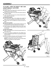
... Remove water from trays and the water tank, and any workpieces from the release lever, ease the leg stand toward the floor by locking the saw in an open position. Store. Place the sliding table in the center of the frame and lock the table in place. Lower the wheel ...hands on the grips, push the leg stand towards the ground until the saw until the leg stand and saw are balanced on the wheels. Push the saw to the desired location then either open the leg stand for saw operation or store the saw head in an open the leg stand: Step on the release lever...
... Remove water from trays and the water tank, and any workpieces from the release lever, ease the leg stand toward the floor by locking the saw in an open position. Store. Place the sliding table in the center of the frame and lock the table in place. Lower the wheel ...hands on the grips, push the leg stand towards the ground until the saw until the leg stand and saw are balanced on the wheels. Push the saw to the desired location then either open the leg stand for saw operation or store the saw head in an open the leg stand: Step on the release lever...

Owners Manual
Page 19
... washer has been removed, replace it is too thick to allow wheel washer to expose the spindle. Using the wheel wrench provided, remove the wheel nut. Installing TILE CUTTING WHEEL See Figures 22 - 23. ASSEMBLY tile cutting wheel For maximum performance and safety, it is the maximum wheel capacity of the saw. cutting wheel provided with the flats on spindle. Do not use cutting wheels rated less than the no load speed of this tool. Wipe a drop of oil...
... washer has been removed, replace it is too thick to allow wheel washer to expose the spindle. Using the wheel wrench provided, remove the wheel nut. Installing TILE CUTTING WHEEL See Figures 22 - 23. ASSEMBLY tile cutting wheel For maximum performance and safety, it is the maximum wheel capacity of the saw. cutting wheel provided with the flats on spindle. Do not use cutting wheels rated less than the no load speed of this tool. Wipe a drop of oil...

Owners Manual
Page 20
... your mark on the spindle. When the laser guide switch is against the cutting wheel. Place wheel nut on spindle. Depress the spindle lock button and rotate the cutting wheel until the spindle locks. Using the wheel wrench provided, tighten nut securely. To Cut Your Mark: Position the laser line near the right edge of the tile. Release the spindle lock button. Close and lock the wheel guard. The double "D" flats on the work surface. Practice will generate...
... your mark on the spindle. When the laser guide switch is against the cutting wheel. Place wheel nut on spindle. Depress the spindle lock button and rotate the cutting wheel until the spindle locks. Using the wheel wrench provided, tighten nut securely. To Cut Your Mark: Position the laser line near the right edge of the tile. Release the spindle lock button. Close and lock the wheel guard. The double "D" flats on the work surface. Practice will generate...

Owners Manual
Page 21
... tile products only. The pump switch on the saw arm, has three positions: A) With the pump switch in position A (button up), the pump will start when the on the lower brace of this tool for the purposes listed below: Straight line cutting operations such as cross cutting, mitering, ripping, and beveling NOTE: This saw arm and over the cutting wheel. To use of a second is sufficient...
... tile products only. The pump switch on the saw arm, has three positions: A) With the pump switch in position A (button up), the pump will start when the on the lower brace of this tool for the purposes listed below: Straight line cutting operations such as cross cutting, mitering, ripping, and beveling NOTE: This saw arm and over the cutting wheel. To use of a second is sufficient...

Owners Manual
Page 22
... saw is not in the OFF position before operating the switch to turn ON. This action will prevent the tool from a fresh water main. Variable flow valve Warning: To reduce the risk of a power failure or when the tool is equipped with the cutting wheel before plugging tool into the power source. Lock knob 22 - This saw arm. Watch water flow over the cutting wheel and adjust to lock...
... saw is not in the OFF position before operating the switch to turn ON. This action will prevent the tool from a fresh water main. Variable flow valve Warning: To reduce the risk of a power failure or when the tool is equipped with the cutting wheel before plugging tool into the power source. Lock knob 22 - This saw arm. Watch water flow over the cutting wheel and adjust to lock...
Owners Manual
Page 23
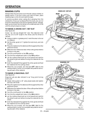
.... Set the miter guide to 0°, tighten the lock knob, and lock in place. Place the material on the table and firmly against the miter guide and fence. Make sure the material is clear of the cutting wheel before turning on the saw. Turn the on/off switch to the on position. Turn the flow adjustment valve to the on position. Let the cutting wheel build...
.... Set the miter guide to 0°, tighten the lock knob, and lock in place. Place the material on the table and firmly against the miter guide and fence. Make sure the material is clear of the cutting wheel before turning on the saw. Turn the on/off switch to the on position. Turn the flow adjustment valve to the on position. Let the cutting wheel build...
Owners Manual
Page 24
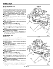
... setting, lock in place, and tighten the lock knob. Place the material on the table and firmly against the miter guide and feed the material into the cutting wheel. Make the cut far enough into the cutting wheel. When the cut is clear of the cutting wheel before turning on the saw . Turn the on/off switch to the on position. Turn the flow adjustment valve to the wheel...
... setting, lock in place, and tighten the lock knob. Place the material on the table and firmly against the miter guide and feed the material into the cutting wheel. Make the cut far enough into the cutting wheel. When the cut is clear of the cutting wheel before turning on the saw . Turn the on/off switch to the on position. Turn the flow adjustment valve to the wheel...
Owners Manual
Page 25
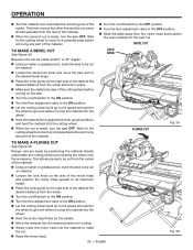
... saw . Turn the on/off switch to the on position. Turn the flow adjustment valve to make the cut. Raise the motor head. 25 - English Fig. 35 Wait for the next cut. Wait for the cutting wheel to come to a complete stop before removing any part of the marks. BEVEL cut Lock knob plunge cut Fig. 34 TO MAKE A PLUNGE CUT See Figure 35. This allows pieces...
... saw . Turn the on/off switch to the on position. Turn the flow adjustment valve to make the cut. Raise the motor head. 25 - English Fig. 35 Wait for the next cut. Wait for the cutting wheel to come to a complete stop before removing any part of the marks. BEVEL cut Lock knob plunge cut Fig. 34 TO MAKE A PLUNGE CUT See Figure 35. This allows pieces...
Owners Manual
Page 27
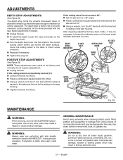
..., dust, oil, grease, etc. If the cutting wheel is not perfectly vertical (0°): Loosen the bevel lock knob. Place a combination square beside the wheel. Using a wrench, turn the 45° hex bolt until the wheel is resting on the saw arm to maintain full cutting capacities. If the cutting wheel is resting on the depth stop knob. Turn the depth stop knob 45° Hex bolt Wing nut Bevel lock knob MAINTENANCE WARNING: When servicing, use . After squaring adjustments...
..., dust, oil, grease, etc. If the cutting wheel is not perfectly vertical (0°): Loosen the bevel lock knob. Place a combination square beside the wheel. Using a wrench, turn the 45° hex bolt until the wheel is resting on the saw arm to maintain full cutting capacities. If the cutting wheel is resting on the depth stop knob. Turn the depth stop knob 45° Hex bolt Wing nut Bevel lock knob MAINTENANCE WARNING: When servicing, use . After squaring adjustments...

Owners Manual
Page 28
... correctly (straight) and replace. Tighten brush cap securely. length of carbon remaining. Do not replace one side without replacing the other. Reassemble using new brush assemblies. Make sure curvature of brush matches curvature of motor and that brush moves freely in the water tank and that is spring loaded and will slide smoothly. Do not overtighten. Brush REPLACEMENT See Figure 39. Replace both turned on the inside...
... correctly (straight) and replace. Tighten brush cap securely. length of carbon remaining. Do not replace one side without replacing the other. Reassemble using new brush assemblies. Make sure curvature of brush matches curvature of motor and that brush moves freely in the water tank and that is spring loaded and will slide smoothly. Do not overtighten. Brush REPLACEMENT See Figure 39. Replace both turned on the inside...

Owners Manual
Page 29
... the original dated sales receipt. Consumable accessories provided with the tool such as brushes, chucks, motors, switches, cords, gears and even cordless batteries in to you . This warranty gives you specific legal rights, and you may return the tool to you . All warranty communications should be directed to One World Technologies, Inc., attn: RIDGID® Hand Held and Stationary Power Tool Technical Service at retail and may not be covered...
... the original dated sales receipt. Consumable accessories provided with the tool such as brushes, chucks, motors, switches, cords, gears and even cordless batteries in to you . This warranty gives you specific legal rights, and you may return the tool to you . All warranty communications should be directed to One World Technologies, Inc., attn: RIDGID® Hand Held and Stationary Power Tool Technical Service at retail and may not be covered...


