
Operation Manual
Page 3
... for an extension cord 25 feet or less in good working outdoors. These cords are recommended when working order. REMOVE ADJUSTING KEYS AND WRENCHES. For example, pipes, radiators, ranges, refrigerator enclosures. KEEP GUARDS IN PLACE and in length. It will draw. Use only a ... a vise to a complete stop. PROTECT YOUR LUNGS. Before further use it comes to hold work or around or over the blade while blade is damaged should wear safety glasses and be carefully checked to see that is dusty. PROTECT YOUR HEARING. The smaller the gauge ...
... for an extension cord 25 feet or less in good working outdoors. These cords are recommended when working order. REMOVE ADJUSTING KEYS AND WRENCHES. For example, pipes, radiators, ranges, refrigerator enclosures. KEEP GUARDS IN PLACE and in length. It will draw. Use only a ... a vise to a complete stop. PROTECT YOUR LUNGS. Before further use it comes to hold work or around or over the blade while blade is damaged should wear safety glasses and be carefully checked to see that is dusty. PROTECT YOUR HEARING. The smaller the gauge ...

Operation Manual
Page 9
Cutting Depth at 90 3-1/2 in . Rating 120 V~, 15 Amps, 60 Hz No Load Speed 4,400 r/min. (RPM) RIVING KNIFE ANTI-KICKBACK PAWLS BLADE GUARD ASSEMBLY SAW BLADE MITER GAUGE RIP FENCE MICRO-ADJUST WHEEL LOCKING LEVER FRONT RAIL BLADE WRENCHES BEVEL SCALE GRIPS BLADE AND BLADE WRENCH STORAGE LEG STAND BEVEL LOCKING LEVER SWITCH ASSEMBLY BEVEL ADJUSTING HANDWHEEL BEVEL INDICATOR HEIGHT ADJUSTING KNOB BLADE HEIGHT LOCK KNOB Fig. 3 9 Blade Arbor 5/8 in . Cutting Depth at 45 2-1/2 in . FEATURES PRODUCT SPECIFICATIONS Blade Diameter 10 in .
Cutting Depth at 90 3-1/2 in . Rating 120 V~, 15 Amps, 60 Hz No Load Speed 4,400 r/min. (RPM) RIVING KNIFE ANTI-KICKBACK PAWLS BLADE GUARD ASSEMBLY SAW BLADE MITER GAUGE RIP FENCE MICRO-ADJUST WHEEL LOCKING LEVER FRONT RAIL BLADE WRENCHES BEVEL SCALE GRIPS BLADE AND BLADE WRENCH STORAGE LEG STAND BEVEL LOCKING LEVER SWITCH ASSEMBLY BEVEL ADJUSTING HANDWHEEL BEVEL INDICATOR HEIGHT ADJUSTING KNOB BLADE HEIGHT LOCK KNOB Fig. 3 9 Blade Arbor 5/8 in . Cutting Depth at 45 2-1/2 in . FEATURES PRODUCT SPECIFICATIONS Blade Diameter 10 in .

Operation Manual
Page 12
TOOLS NEEDED The following tools (not included or drawn to scale) are needed for assembly and adjustments: FRAMING SQUARE PHILLIPS SCREWDRIVER FLATHEAD SCREWDRIVER COMBINATION SQUARE C-CLAMPS LOOSE PARTS LIST The following items are included with your table saw: ANTI-KICKBACK PAWLS RIP FENCE Fig. 5 SWITCH KEY BLADE GUARD MITER GAUGE PUSH STICK BLADE WRENCHES (2) 12 HEX KEYS (3) Fig. 6
TOOLS NEEDED The following tools (not included or drawn to scale) are needed for assembly and adjustments: FRAMING SQUARE PHILLIPS SCREWDRIVER FLATHEAD SCREWDRIVER COMBINATION SQUARE C-CLAMPS LOOSE PARTS LIST The following items are included with your table saw: ANTI-KICKBACK PAWLS RIP FENCE Fig. 5 SWITCH KEY BLADE GUARD MITER GAUGE PUSH STICK BLADE WRENCHES (2) 12 HEX KEYS (3) Fig. 6

Operation Manual
Page 18
... convenient storage areas (one on a flat, level surface, the saw should not move or rock from side to side. WING NUT PUSH STICK LEVELING FOOT BLADE BLADE WRENCHES WING NUT MITER GAUGE Fig. 13 ANTI-KICKBACK PAWLS ANTI-KICKBACK PAWLS...
... convenient storage areas (one on a flat, level surface, the saw should not move or rock from side to side. WING NUT PUSH STICK LEVELING FOOT BLADE BLADE WRENCHES WING NUT MITER GAUGE Fig. 13 ANTI-KICKBACK PAWLS ANTI-KICKBACK PAWLS...
Operation Manual
Page 21
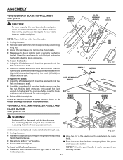
... be installed for free blade rotation. NOTE: Pull on the right side of the other wrench over the hex nut. Holding both wrenches firmly, pull the outside wrench (right side) forward while pushing the inside (left . BLADE WRENCH (LEFT) HANDLE ANTI-KICKBACK PAWLS BLADE GUARD BLADE WRENCH (RIGHT) SET SCREW .... Reinstall the throat plate. Align the slot in the pawls over the hex nut. To tighten the blade: Using the left blade wrench, insert the open end onto the flats on the arbor shaft. Insert the closed end of the anti- Fig....
... be installed for free blade rotation. NOTE: Pull on the right side of the other wrench over the hex nut. Holding both wrenches firmly, pull the outside wrench (right side) forward while pushing the inside (left . BLADE WRENCH (LEFT) HANDLE ANTI-KICKBACK PAWLS BLADE GUARD BLADE WRENCH (RIGHT) SET SCREW .... Reinstall the throat plate. Align the slot in the pawls over the hex nut. To tighten the blade: Using the left blade wrench, insert the open end onto the flats on the arbor shaft. Insert the closed end of the anti- Fig....

Operation Manual
Page 38
...sure the hex nut is securely pushed to the left. TO REPLACE THE BLADE See Figures 55 - 56. Holding both wrenches firmly, pull the outside wrench (right side) forward while pushing the inside (left blade wrench, insert the open end onto the flats on the arbor shaft (the ...your setups carefully with a framing square and make sure it turns freely. Lower the saw blade and reinstall the throat plate. 38 BLADE WRENCH (LEFT) ARBOR SHAFT BLADE WRENCH (RIGHT) Fig. 55 BLADE BLADE WASHER HEX NUT RELEASE LEVER Fig. 56 Do not overtighten. Lock the release lever. ...
...sure the hex nut is securely pushed to the left. TO REPLACE THE BLADE See Figures 55 - 56. Holding both wrenches firmly, pull the outside wrench (right side) forward while pushing the inside (left blade wrench, insert the open end onto the flats on the arbor shaft (the ...your setups carefully with a framing square and make sure it turns freely. Lower the saw blade and reinstall the throat plate. 38 BLADE WRENCH (LEFT) ARBOR SHAFT BLADE WRENCH (RIGHT) Fig. 55 BLADE BLADE WASHER HEX NUT RELEASE LEVER Fig. 56 Do not overtighten. Lock the release lever. ...

Operation Manual
Page 40
... loosen the indicator adjusting screw and adjust indicator. Retighten screw. Lock the bevel locking lever. Screw the 45º stop screw until blade is too loose, turn the flat head screw in a counterclockwise direction. Retighten set screw. 45˚ STOP SCREW MITER GAUGE ROD 0° ADJUSTABLE...; Adjust the stop screw until it is even with the top of the 0º stop screw at 0º and plus or minus 45º with a wrench. Place a 90º square against the stop screws. Loosen the lock nut of the saw table using a hex key. ...
... loosen the indicator adjusting screw and adjust indicator. Retighten screw. Lock the bevel locking lever. Screw the 45º stop screw until blade is too loose, turn the flat head screw in a counterclockwise direction. Retighten set screw. 45˚ STOP SCREW MITER GAUGE ROD 0° ADJUSTABLE...; Adjust the stop screw until it is even with the top of the 0º stop screw at 0º and plus or minus 45º with a wrench. Place a 90º square against the stop screws. Loosen the lock nut of the saw table using a hex key. ...


