
Operation Manual
Page 2
..., and dependability have been given top priority in the design of Terms...8 Features...9-11 Tools Needed...13 Loose Parts...14-22 Assembly...15-23 Operation...23-37 Adjustments...38-42 Maintenance...43-44 Accessories...44 Troubleshooting...45-46 Warranty...47 ...
..., and dependability have been given top priority in the design of Terms...8 Features...9-11 Tools Needed...13 Loose Parts...14-22 Assembly...15-23 Operation...23-37 Adjustments...38-42 Maintenance...43-44 Accessories...44 Troubleshooting...45-46 Warranty...47 ...

Operation Manual
Page 9
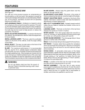
Rating 120 V~, 15 Amps, 60 Hz No Load Speed 4,400 r/min. (RPM) RIVING KNIFE ANTI-KICKBACK PAWLS BLADE GUARD ASSEMBLY SAW BLADE MITER GAUGE RIP FENCE MICRO-ADJUST WHEEL LOCKING LEVER FRONT RAIL BLADE WRENCHES BEVEL SCALE GRIPS BLADE AND BLADE WRENCH STORAGE LEG STAND BEVEL LOCKING LEVER SWITCH ASSEMBLY BEVEL ADJUSTING HANDWHEEL BEVEL INDICATOR HEIGHT ADJUSTING KNOB BLADE HEIGHT LOCK KNOB Fig. 3 9 Blade Arbor 5/8 in . FEATURES PRODUCT SPECIFICATIONS Blade Diameter 10 in . Cutting Depth at 90 3-1/2 in . Cutting Depth at 45 2-1/2 in .
Rating 120 V~, 15 Amps, 60 Hz No Load Speed 4,400 r/min. (RPM) RIVING KNIFE ANTI-KICKBACK PAWLS BLADE GUARD ASSEMBLY SAW BLADE MITER GAUGE RIP FENCE MICRO-ADJUST WHEEL LOCKING LEVER FRONT RAIL BLADE WRENCHES BEVEL SCALE GRIPS BLADE AND BLADE WRENCH STORAGE LEG STAND BEVEL LOCKING LEVER SWITCH ASSEMBLY BEVEL ADJUSTING HANDWHEEL BEVEL INDICATOR HEIGHT ADJUSTING KNOB BLADE HEIGHT LOCK KNOB Fig. 3 9 Blade Arbor 5/8 in . FEATURES PRODUCT SPECIFICATIONS Blade Diameter 10 in . Cutting Depth at 90 3-1/2 in . Cutting Depth at 45 2-1/2 in .
Operation Manual
Page 10
... dig into the wood to use blades rated less than the saw has an easy access power switch located below the saw blade teeth. SWITCH ASSEMBLY - BLADE HEIGHT LOCK KNOB - The miter gauge rides in personal injury. A removable metal piece of the blade. To lock the switch in ....operator. When in this product requires an understanding of the information on the front of the cabinet, locks the angle setting of the blade guard assembly, slightly thinner than the saw . The easy-to-read scale provides precise measurements for specific operations such as a knowledge of the blade. ...
... dig into the wood to use blades rated less than the saw has an easy access power switch located below the saw blade teeth. SWITCH ASSEMBLY - BLADE HEIGHT LOCK KNOB - The miter gauge rides in personal injury. A removable metal piece of the blade. To lock the switch in ....operator. When in this product requires an understanding of the information on the front of the cabinet, locks the angle setting of the blade guard assembly, slightly thinner than the saw . The easy-to-read scale provides precise measurements for specific operations such as a knowledge of the blade. ...

Operation Manual
Page 11
... when the tool is set with a handwheel on the front rail shows the distance between the rip fence and the blade. The blade guard assembly includes: riving knife, anti-kickback pawls, and blade guard. The height of the blade is not in use the blade guard...POSITION Fig. 4 11 WARNING: ALWAYS make sure the switch is very important to be kicked back toward the operator and result in contact with a switch assembly that has a built-in a safe place. FEATURES OPERATING COMPONENTS The upper portion of the blade projects up through -sawing operations. This feature is equipped with...
... when the tool is set with a handwheel on the front rail shows the distance between the rip fence and the blade. The blade guard assembly includes: riving knife, anti-kickback pawls, and blade guard. The height of the blade is not in use the blade guard...POSITION Fig. 4 11 WARNING: ALWAYS make sure the switch is very important to be kicked back toward the operator and result in contact with a switch assembly that has a built-in a safe place. FEATURES OPERATING COMPONENTS The upper portion of the blade projects up through -sawing operations. This feature is equipped with...

Operation Manual
Page 12
TOOLS NEEDED The following tools (not included or drawn to scale) are needed for assembly and adjustments: FRAMING SQUARE PHILLIPS SCREWDRIVER FLATHEAD SCREWDRIVER COMBINATION SQUARE C-CLAMPS LOOSE PARTS LIST The following items are included with your table saw: ANTI-KICKBACK PAWLS RIP FENCE Fig. 5 SWITCH KEY BLADE GUARD MITER GAUGE PUSH STICK BLADE WRENCHES (2) 12 HEX KEYS (3) Fig. 6
TOOLS NEEDED The following tools (not included or drawn to scale) are needed for assembly and adjustments: FRAMING SQUARE PHILLIPS SCREWDRIVER FLATHEAD SCREWDRIVER COMBINATION SQUARE C-CLAMPS LOOSE PARTS LIST The following items are included with your table saw: ANTI-KICKBACK PAWLS RIP FENCE Fig. 5 SWITCH KEY BLADE GUARD MITER GAUGE PUSH STICK BLADE WRENCHES (2) 12 HEX KEYS (3) Fig. 6

Operation Manual
Page 13
LOOSE PARTS LIST SCREW UPPER TUBE HANDLE SECTION CENTER BRACE CARRIAGE BOLT OUTER TUBE LOCK NUT LARGE SPACER SMALL SPACER FLAT WASHER, SMALL WHEEL LOCK NUT FLAT WASHER, LARGE INNER LEG ASSEMBLY Fig. 7 13
LOOSE PARTS LIST SCREW UPPER TUBE HANDLE SECTION CENTER BRACE CARRIAGE BOLT OUTER TUBE LOCK NUT LARGE SPACER SMALL SPACER FLAT WASHER, SMALL WHEEL LOCK NUT FLAT WASHER, LARGE INNER LEG ASSEMBLY Fig. 7 13

Operation Manual
Page 14
... of this product with this tool. Bolts should be mounted to a firm supporting surface such as a workbench or leg stand. After assembling it, check for this purpose. Use of sufficient length to accommodate the saw must be bolted securely using 1/4 in. Ignoring these precautions... can occur during shipping. Do not discard the packing material until assembly is complete. MOUNTING HOLES The table saw base, washers, lock washers, wing nuts, and the thickness of a product that no breakage or...
... of this product with this tool. Bolts should be mounted to a firm supporting surface such as a workbench or leg stand. After assembling it, check for this purpose. Use of sufficient length to accommodate the saw must be bolted securely using 1/4 in. Ignoring these precautions... can occur during shipping. Do not discard the packing material until assembly is complete. MOUNTING HOLES The table saw base, washers, lock washers, wing nuts, and the thickness of a product that no breakage or...

Operation Manual
Page 15
... Slide the center brace onto the bolt and secure in place using a lock nut. The tube with the stop pin under the pedal assembly latch. Only tighten fasteners securely when you are movable. contact an authorized service center for the other side. Place the center brace on... the axles on the left side) to letter and fingertighten all fasteners. Secure in place using carriage bolts, spacers, and lock nuts. For easier assembly, match letter to the leg stand using a lock nut. Repeat for assistance. If the leg stand will not lock, do not use , verify...
... Slide the center brace onto the bolt and secure in place using a lock nut. The tube with the stop pin under the pedal assembly latch. Only tighten fasteners securely when you are movable. contact an authorized service center for the other side. Place the center brace on... the axles on the left side) to letter and fingertighten all fasteners. Secure in place using carriage bolts, spacers, and lock nuts. For easier assembly, match letter to the leg stand using a lock nut. Repeat for assistance. If the leg stand will not lock, do not use , verify...

Operation Manual
Page 16
.... The saw and into the hole in the stand. Add a lock washer, flat washer, ring terminal (from switch box), and a hex nut. Hand tighten. ASSEMBLY MOUNTING THE LEG STAND ON THE TABLE SAW BASE See Figure 9.
.... The saw and into the hole in the stand. Add a lock washer, flat washer, ring terminal (from switch box), and a hex nut. Hand tighten. ASSEMBLY MOUNTING THE LEG STAND ON THE TABLE SAW BASE See Figure 9.

Operation Manual
Page 17
NOTE: The release lever will close over the center brace locking the leg stand in an open position. ASSEMBLY TO OPEN THE LEG STAND See Figures 10 - 12 Grasp the grips on the saw table and stand it upright as shown below. ...
NOTE: The release lever will close over the center brace locking the leg stand in an open position. ASSEMBLY TO OPEN THE LEG STAND See Figures 10 - 12 Grasp the grips on the saw table and stand it upright as shown below. ...

Operation Manual
Page 18
... WRENCHES WING NUT MITER GAUGE Fig. 13 ANTI-KICKBACK PAWLS ANTI-KICKBACK PAWLS / BLADE GUARD STORAGE BLADE GUARD Fig. 14 18 RIP FENCE Fig. 15 ASSEMBLY TO SECURE/LEVEL THE SAW See Figure 13. With the leg stand open and the table saw resting on either side of the saw cabinet...
... WRENCHES WING NUT MITER GAUGE Fig. 13 ANTI-KICKBACK PAWLS ANTI-KICKBACK PAWLS / BLADE GUARD STORAGE BLADE GUARD Fig. 14 18 RIP FENCE Fig. 15 ASSEMBLY TO SECURE/LEVEL THE SAW See Figure 13. With the leg stand open and the table saw resting on either side of the saw cabinet...

Operation Manual
Page 19
... tool. Remove and securely store any workpieces from the body. Push the table saw until the release lever clicks and locks into place. ASSEMBLY TO CLOSE THE LEG STAND AND MOVE THE SAW See Figures 16 - 19. Remove any tools or accessories such as rip fence, miter gauge...
... tool. Remove and securely store any workpieces from the body. Push the table saw until the release lever clicks and locks into place. ASSEMBLY TO CLOSE THE LEG STAND AND MOVE THE SAW See Figures 16 - 19. Remove any tools or accessories such as rip fence, miter gauge...

Operation Manual
Page 20
... release lever by pulling it up " position for all other cutting operations. Unplug the saw table. TO CHANGE RIVING KNIFE POSITIONS See Figure 21. ASSEMBLY TO REMOVE/REPLACE/ALIGN THE THROAT PLATE See Figure 20. This saw is shipped with the saw table. To reinstall the throat plate: first...
... release lever by pulling it up " position for all other cutting operations. Unplug the saw table. TO CHANGE RIVING KNIFE POSITIONS See Figure 21. ASSEMBLY TO REMOVE/REPLACE/ALIGN THE THROAT PLATE See Figure 20. This saw is shipped with the saw table. To reinstall the throat plate: first...
Operation Manual
Page 21
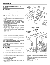
...handle down toward the front of serious personal injury. Make sure the blade nut is securely pushed to To Check and Align the Blade Guard Assembly. BLADE WRENCH (LEFT) HANDLE ANTI-KICKBACK PAWLS BLADE GUARD BLADE WRENCH (RIGHT) SET SCREW HEX NUT BUTTON Fig. 22 GUARD LEVER WARNING:... Replace dull or damaged anti-kickback pawls. ASSEMBLY TO CHECK SAW BLADE INSTALLATION See Figure 22. CAUTION: To work properly, the saw blade and remove the throat plate. Make sure...
...handle down toward the front of serious personal injury. Make sure the blade nut is securely pushed to To Check and Align the Blade Guard Assembly. BLADE WRENCH (LEFT) HANDLE ANTI-KICKBACK PAWLS BLADE GUARD BLADE WRENCH (RIGHT) SET SCREW HEX NUT BUTTON Fig. 22 GUARD LEVER WARNING:... Replace dull or damaged anti-kickback pawls. ASSEMBLY TO CHECK SAW BLADE INSTALLATION See Figure 22. CAUTION: To work properly, the saw blade and remove the throat plate. Make sure...

Operation Manual
Page 22
...riving knife. Refer to back of the riving knife. To adjust (horizontally and vertically): Remove the anti-kickback pawls and blade guard assembly. Loosen the screws holding the mounting bracket. Reposition the riving knife left or right as needed to the table (see ... blade, adjustment is not in place by turning the height adjusting knob clockwise. Remove the anti-kickback pawls and blade guard assembly. TO CHECK AND ALIGN THE RIVING KNIFE AND SAW BLADE See Figure 25. To check alignment of the guard down . CORRECT INCORRECT ...
...riving knife. Refer to back of the riving knife. To adjust (horizontally and vertically): Remove the anti-kickback pawls and blade guard assembly. Loosen the screws holding the mounting bracket. Reposition the riving knife left or right as needed to the table (see ... blade, adjustment is not in place by turning the height adjusting knob clockwise. Remove the anti-kickback pawls and blade guard assembly. TO CHECK AND ALIGN THE RIVING KNIFE AND SAW BLADE See Figure 25. To check alignment of the guard down . CORRECT INCORRECT ...

Operation Manual
Page 28
... lightly touches the right side of this adjustment. When securely locked, the locking lever should point downward. NOTE: The anti-kickback pawls and blade guard assembly must be erased and reset. With the miter gauge in the Adjustments section of the saw table so that the red line is complete.... Unplug the saw. Place the rip fence on the front rail. Reinstall the blade guard assembly when the adjustment is located over the "zero" line on the right rip scale on the saw blade.
... lightly touches the right side of this adjustment. When securely locked, the locking lever should point downward. NOTE: The anti-kickback pawls and blade guard assembly must be erased and reset. With the miter gauge in the Adjustments section of the saw table so that the red line is complete.... Unplug the saw. Place the rip fence on the front rail. Reinstall the blade guard assembly when the adjustment is located over the "zero" line on the right rip scale on the saw blade.

Operation Manual
Page 31
CROSS CUT PLACE RIGHT HAND MITER GAUGE HERE SWITCH IN LOCKED POSITION Fig. 44 WARNING: Make sure the blade guard assembly is installed and working properly to the correct depth for ripping and cross cut on the workpiece. SWITCH KEY Fig. 45 When the cut ...
CROSS CUT PLACE RIGHT HAND MITER GAUGE HERE SWITCH IN LOCKED POSITION Fig. 44 WARNING: Make sure the blade guard assembly is installed and working properly to the correct depth for ripping and cross cut on the workpiece. SWITCH KEY Fig. 45 When the cut ...

Operation Manual
Page 32
... up to full speed before removing the workpiece. PUSH BLOCK BLADE STRAIGHT MITER CUT Fig. 46 MITER GAUGE ANGLED WARNING: Make sure the blade guard assembly is installed and working properly to move the piece through the cut and past the blade. When the cut work. Make sure the... the saw for the blade to come to avoid serious personal injury. OPERATION MAKING A RIP CUT See Figure 46. WARNING: Make sure the blade guard assembly is clear of the table.
... up to full speed before removing the workpiece. PUSH BLOCK BLADE STRAIGHT MITER CUT Fig. 46 MITER GAUGE ANGLED WARNING: Make sure the blade guard assembly is installed and working properly to move the piece through the cut and past the blade. When the cut work. Make sure the... the saw for the blade to come to avoid serious personal injury. OPERATION MAKING A RIP CUT See Figure 46. WARNING: Make sure the blade guard assembly is clear of the table.

Operation Manual
Page 33
... . Let the saw off. tor is made, turn the saw blade build up to avoid serious personal injury. WARNING: Make sure the blade guard assembly is clear of serious personal injury Remove the rip fence by lifting the locking lever. Unlock the bevel locking lever. Turn the...
... . Let the saw off. tor is made, turn the saw blade build up to avoid serious personal injury. WARNING: Make sure the blade guard assembly is clear of serious personal injury Remove the rip fence by lifting the locking lever. Unlock the bevel locking lever. Turn the...

Operation Manual
Page 34
... be on the table with the edge flush against the rip fence. BLADE ANGLED BEVEL RIP CUT RIP FENCE WARNING: Make sure the blade guard assembly is made contact with both the rip fence and the surface of the blade to a complete stop before feeding the workpiece into the blade. ...
... be on the table with the edge flush against the rip fence. BLADE ANGLED BEVEL RIP CUT RIP FENCE WARNING: Make sure the blade guard assembly is made contact with both the rip fence and the surface of the blade to a complete stop before feeding the workpiece into the blade. ...

