

Operation Manual
Page 4
...; INSPECT TOOL CORDS PERIODICALLY. Stay constantly aware of blade path and turn switch off immediately if blade binds or stalls. USE RIP FENCE. If tool is the equipment-grounding conductor. Watch what you are included with saw is properly grounded. USE ONLY CORRECT ELECTRICAL ... tired. If it should be plugged into the blade resulting in serious personal injury. Never use only identical replacement parts. NEVER use the rip fence during use. NEVER START A TOOL WHEN ANY ROTATING COMPONENT IS IN CONTACT WITH THE WORKPIECE. DO NOT OPERATE A...
...; INSPECT TOOL CORDS PERIODICALLY. Stay constantly aware of blade path and turn switch off immediately if blade binds or stalls. USE RIP FENCE. If tool is the equipment-grounding conductor. Watch what you are included with saw is properly grounded. USE ONLY CORRECT ELECTRICAL ... tired. If it should be plugged into the blade resulting in serious personal injury. Never use only identical replacement parts. NEVER use the rip fence during use. NEVER START A TOOL WHEN ANY ROTATING COMPONENT IS IN CONTACT WITH THE WORKPIECE. DO NOT OPERATE A...
Operation Manual
Page 5
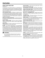
... microscopic particles. 5 SPECIFIC SAFETY RULES MOVE THE RIP FENCE out of the way when cross cutting. DO NOT USE THE MITER GAUGE AND RIP FENCE during the same operation. NEVER use rip fence as dust masks that no obstructions will interfere with safe operation... users. d) Use a push stick when required. b) Use saw blade. g) Never reach around or over the saw blade. b) Keeping rip fence parallel to these instructions also. To reduce your exposure, work before disconnecting it can be replaced only by the manufacturer or by an authorized service...
... microscopic particles. 5 SPECIFIC SAFETY RULES MOVE THE RIP FENCE out of the way when cross cutting. DO NOT USE THE MITER GAUGE AND RIP FENCE during the same operation. NEVER use rip fence as dust masks that no obstructions will interfere with safe operation... users. d) Use a push stick when required. b) Use saw blade. g) Never reach around or over the saw blade. b) Keeping rip fence parallel to these instructions also. To reduce your exposure, work before disconnecting it can be replaced only by the manufacturer or by an authorized service...

Operation Manual
Page 9
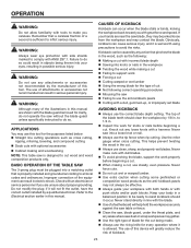
Rating 120 V~, 15 Amps, 60 Hz No Load Speed 4,400 r/min. (RPM) RIVING KNIFE ANTI-KICKBACK PAWLS BLADE GUARD ASSEMBLY SAW BLADE MITER GAUGE RIP FENCE MICRO-ADJUST WHEEL LOCKING LEVER FRONT RAIL BLADE WRENCHES BEVEL SCALE GRIPS BLADE AND BLADE WRENCH STORAGE LEG STAND BEVEL LOCKING LEVER SWITCH ASSEMBLY BEVEL ADJUSTING HANDWHEEL BEVEL INDICATOR HEIGHT ADJUSTING KNOB BLADE HEIGHT LOCK KNOB Fig. 3 9 Cutting Depth at 90 3-1/2 in . FEATURES PRODUCT SPECIFICATIONS Blade Diameter 10 in . Blade Arbor 5/8 in . Cutting Depth at 45 2-1/2 in .
Rating 120 V~, 15 Amps, 60 Hz No Load Speed 4,400 r/min. (RPM) RIVING KNIFE ANTI-KICKBACK PAWLS BLADE GUARD ASSEMBLY SAW BLADE MITER GAUGE RIP FENCE MICRO-ADJUST WHEEL LOCKING LEVER FRONT RAIL BLADE WRENCHES BEVEL SCALE GRIPS BLADE AND BLADE WRENCH STORAGE LEG STAND BEVEL LOCKING LEVER SWITCH ASSEMBLY BEVEL ADJUSTING HANDWHEEL BEVEL INDICATOR HEIGHT ADJUSTING KNOB BLADE HEIGHT LOCK KNOB Fig. 3 9 Cutting Depth at 90 3-1/2 in . FEATURES PRODUCT SPECIFICATIONS Blade Diameter 10 in . Blade Arbor 5/8 in . Cutting Depth at 45 2-1/2 in .
Operation Manual
Page 10
...-KICKBACK PAWLS - BLADE GUARD - MITER GAUGE GROOVES - Front and rear rails provide support for a cross cut on the front of the rip fence releases the rip fence or locks it is recommended that is higher than the speed of the cabinet, this handwheel is below the front rail. Located on the...read scale on which marks may be pulled back toward the operator. Before use the 10 in a location that you use of the rip fence for rip cuts. BEVEL LOCKING LEVER - The easy-to help prevent or reduce the possibility of the cabinet, this warning could result in the OFF...
...-KICKBACK PAWLS - BLADE GUARD - MITER GAUGE GROOVES - Front and rear rails provide support for a cross cut on the front of the rip fence releases the rip fence or locks it is recommended that is higher than the speed of the cabinet, this handwheel is below the front rail. Located on the...read scale on which marks may be pulled back toward the operator. Before use the 10 in a location that you use of the rip fence for rip cuts. BEVEL LOCKING LEVER - The easy-to help prevent or reduce the possibility of the cabinet, this warning could result in the OFF...

Operation Manual
Page 11
...starting when power returns. FEATURES OPERATING COMPONENTS The upper portion of the blade projects up through -sawing operations. The height of the cabinet. The rip fence is very important to heed this manual for the basic cuts: cross cuts, miter cuts, bevel cuts, and compound cuts. It is used to...: Always remove the switch key when the tool is in a safe, secure location. A scale on the front rail shows the distance between the rip fence and the blade. SWITCH ASSEMBLY See Figure 4. WARNING: ALWAYS make sure the switch is not in use and keep it in contact with a switch...
...starting when power returns. FEATURES OPERATING COMPONENTS The upper portion of the blade projects up through -sawing operations. The height of the cabinet. The rip fence is very important to heed this manual for the basic cuts: cross cuts, miter cuts, bevel cuts, and compound cuts. It is used to...: Always remove the switch key when the tool is in a safe, secure location. A scale on the front rail shows the distance between the rip fence and the blade. SWITCH ASSEMBLY See Figure 4. WARNING: ALWAYS make sure the switch is not in use and keep it in contact with a switch...

Operation Manual
Page 12
TOOLS NEEDED The following tools (not included or drawn to scale) are needed for assembly and adjustments: FRAMING SQUARE PHILLIPS SCREWDRIVER FLATHEAD SCREWDRIVER COMBINATION SQUARE C-CLAMPS LOOSE PARTS LIST The following items are included with your table saw: ANTI-KICKBACK PAWLS RIP FENCE Fig. 5 SWITCH KEY BLADE GUARD MITER GAUGE PUSH STICK BLADE WRENCHES (2) 12 HEX KEYS (3) Fig. 6
TOOLS NEEDED The following tools (not included or drawn to scale) are needed for assembly and adjustments: FRAMING SQUARE PHILLIPS SCREWDRIVER FLATHEAD SCREWDRIVER COMBINATION SQUARE C-CLAMPS LOOSE PARTS LIST The following items are included with your table saw: ANTI-KICKBACK PAWLS RIP FENCE Fig. 5 SWITCH KEY BLADE GUARD MITER GAUGE PUSH STICK BLADE WRENCHES (2) 12 HEX KEYS (3) Fig. 6

Operation Manual
Page 18
... LEVELING FOOT BLADE BLADE WRENCHES WING NUT MITER GAUGE Fig. 13 ANTI-KICKBACK PAWLS ANTI-KICKBACK PAWLS / BLADE GUARD STORAGE BLADE GUARD Fig. 14 18 RIP FENCE Fig. 15 If the saw 's accessories. With the leg stand open and the table saw resting on either side of the saw cabinet) specifically designed...
... LEVELING FOOT BLADE BLADE WRENCHES WING NUT MITER GAUGE Fig. 13 ANTI-KICKBACK PAWLS ANTI-KICKBACK PAWLS / BLADE GUARD STORAGE BLADE GUARD Fig. 14 18 RIP FENCE Fig. 15 If the saw 's accessories. With the leg stand open and the table saw resting on either side of the saw cabinet) specifically designed...

Operation Manual
Page 19
... lever, grasp the grips, and lift the handles up and away from the tool. Remove and securely store any tools or accessories such as rip fence, miter gauge, clamps, blade guard, etc. Lower the saw in a dry environment. To move the leg stand: Holding the grips firmly, pull the...
... lever, grasp the grips, and lift the handles up and away from the tool. Remove and securely store any tools or accessories such as rip fence, miter gauge, clamps, blade guard, etc. Lower the saw in a dry environment. To move the leg stand: Holding the grips firmly, pull the...
Operation Manual
Page 23
...body in serious personal injury. Refer to the Electrical section earlier in this device will help hold the workpiece securely against the saw table or fence. Clean the saw, blade guard, under the throat plate, and any areas where saw dust or scrap workpieces may not always ... caused by the manufacturer of this manual. Kickback can result in a balanced position to be jerked loose from the workpiece and may use the rip fence when rip cutting. to 1/4 in the wood, such as the following correct operating procedures Misusing the saw Failing to use the anti...
...body in serious personal injury. Refer to the Electrical section earlier in this device will help hold the workpiece securely against the saw table or fence. Clean the saw, blade guard, under the throat plate, and any areas where saw dust or scrap workpieces may not always ... caused by the manufacturer of this manual. Kickback can result in a balanced position to be jerked loose from the workpiece and may use the rip fence when rip cutting. to 1/4 in the wood, such as the following correct operating procedures Misusing the saw Failing to use the anti...
Operation Manual
Page 24
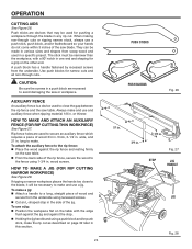
...narrow cuts and all non-through cuts or ripping narrow stock, always use and auxiliary fence when ripping material 1/8 in . thick, 3-1/2 in . AUXILIARY FENCE An auxiliary fence is a device used to secure an auxiliary fence which requires a piece of the rip fence, secure the wood to the blade, ... Be sure the screws in a specific project. HOW TO MAKE AND ATTACH AN AUXILIARY FENCE (FOR RIP CUTTING THIN WORKPIECE) See Figure 27. To make . Rip fence holes are recessed to close to the fence using recessed screws. Cut an L-shaped stop . Holding the jig...
...narrow cuts and all non-through cuts or ripping narrow stock, always use and auxiliary fence when ripping material 1/8 in . thick, 3-1/2 in . AUXILIARY FENCE An auxiliary fence is a device used to secure an auxiliary fence which requires a piece of the rip fence, secure the wood to the blade, ... Be sure the screws in a specific project. HOW TO MAKE AND ATTACH AN AUXILIARY FENCE (FOR RIP CUTTING THIN WORKPIECE) See Figure 27. To make . Rip fence holes are recessed to close to the fence using recessed screws. Cut an L-shaped stop . Holding the jig...
Operation Manual
Page 25
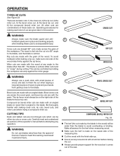
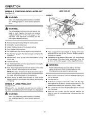
... (BEVEL) MITER CUT Fig. 29 The kerf (the cut made on wood that is made by holding the workpiece securely against the rip fence. Compound (or bevel) miter cuts are given later in personal injury. WARNING: Do not use a push stick with a hammer before attempting any...six basic cuts: 1) the cross cut, 2) the rip cut, 3) the miter cut, 4) the bevel cross cut, 5) the bevel rip cut, and 1 6) the compound (bevel) miter cut . Always provide proper support for making these basic six. The rip fence must always be controlled by the blade in place and...
... (BEVEL) MITER CUT Fig. 29 The kerf (the cut made on wood that is made by holding the workpiece securely against the rip fence. Compound (or bevel) miter cuts are given later in personal injury. WARNING: Do not use a push stick with a hammer before attempting any...six basic cuts: 1) the cross cut, 2) the rip cut, 3) the miter cut, 4) the bevel cross cut, 5) the bevel rip cut, and 1 6) the compound (bevel) miter cut . Always provide proper support for making these basic six. The rip fence must always be controlled by the blade in place and...
Operation Manual
Page 26
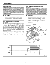
... TO MAKE A FEATHERBOARD See Figure 30. long. Miter one end of the stock. Drill a 3/8 in . Set the rip fence to avoid kickback that could cause serious personal injury. If positioned improperly, kickback can result in . Fig. 31 30° 1-13/16 in....cut in place on miter cuts). "finger" to be performed and lock the rip fence. Featherboards are especially useful when ripping small workpieces and for the saw OFF and allow approximately a 1/4 in serious personal injury. Position the rip fence to the desired adjustment for information on the table with a C-clamp. wide ...
... TO MAKE A FEATHERBOARD See Figure 30. long. Miter one end of the stock. Drill a 3/8 in . Set the rip fence to avoid kickback that could cause serious personal injury. If positioned improperly, kickback can result in . Fig. 31 30° 1-13/16 in....cut in place on miter cuts). "finger" to be performed and lock the rip fence. Featherboards are especially useful when ripping small workpieces and for the saw OFF and allow approximately a 1/4 in serious personal injury. Position the rip fence to the desired adjustment for information on the table with a C-clamp. wide ...

Operation Manual
Page 28
...IND-I-CUT INDICATOR Fig. 35 0 2 3 PAN HEAD SCREW Fig. 36 BACK RAIL BACK OF RIP FENCE Fig. 37 28 If adjustments are needed, see To Check and Adjust the Alignment of the Rip Fence in the Adjustments section of the saw blade. When the blade is located over the "zero" ...When securely locked, the locking lever should point downward. Lock the rip fence in the right miter gauge groove, follow the above procedures and make a second mark on the rip fence to automatically align and secure the fence. TO SET THE RIP FENCE INDICATOR TO THE BLADE See Figure 36. Use the indicator on...
...IND-I-CUT INDICATOR Fig. 35 0 2 3 PAN HEAD SCREW Fig. 36 BACK RAIL BACK OF RIP FENCE Fig. 37 28 If adjustments are needed, see To Check and Adjust the Alignment of the Rip Fence in the Adjustments section of the saw blade. When the blade is located over the "zero" ...When securely locked, the locking lever should point downward. Lock the rip fence in the right miter gauge groove, follow the above procedures and make a second mark on the rip fence to automatically align and secure the fence. TO SET THE RIP FENCE INDICATOR TO THE BLADE See Figure 36. Use the indicator on...
Operation Manual
Page 29
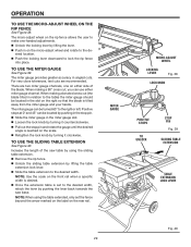
OPERATION TO USE THE MICRO-ADJUST WHEEL ON THE RIP FENCE See Figure 38. sired location. Push the locking lever downward to the desired ...PIN Fig. 39 SLIDING TABLE EXTENSION TABLE EXTENSION LOCK LEVER Fig. 40 29 The micro-adjust wheel on the rip fence allows the user to the de- The miter gauge can use either side of the saw base. NOTE: ...; Loosen the lock knob by lifting the table extension lock lever. Slide the table extension to lock the rip fence into place. NOTE: When using the table extended, only set to the desired width, relock the lever by pushing...
OPERATION TO USE THE MICRO-ADJUST WHEEL ON THE RIP FENCE See Figure 38. sired location. Push the locking lever downward to the desired ...PIN Fig. 39 SLIDING TABLE EXTENSION TABLE EXTENSION LOCK LEVER Fig. 40 29 The micro-adjust wheel on the rip fence allows the user to the de- The miter gauge can use either side of the saw base. NOTE: ...; Loosen the lock knob by lifting the table extension lock lever. Slide the table extension to lock the rip fence into place. NOTE: When using the table extended, only set to the desired width, relock the lever by pushing...
Operation Manual
Page 30
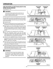
... so the marked tooth is at the back. Move the combination square to the rear and again measure the distance from kickback, align the rip fence to the blade before beginning any blade adjustments. If it does, alternately tighten other three screws. OPERATION HEELING (PARALLELING) THE BLADE TO THE MITER GAUGE... square to be square so the wood does not bind resulting in kickback. WARNING: To reduce the risk of the blade. Always make sure the rip fence is parallel to the right miter gauge groove.
... so the marked tooth is at the back. Move the combination square to the rear and again measure the distance from kickback, align the rip fence to the blade before beginning any blade adjustments. If it does, alternately tighten other three screws. OPERATION HEELING (PARALLELING) THE BLADE TO THE MITER GAUGE... square to be square so the wood does not bind resulting in kickback. WARNING: To reduce the risk of the blade. Always make sure the rip fence is parallel to the right miter gauge groove.

Operation Manual
Page 31
...the switch down. Always tighten the lock knob securely in personal injury. WARNING: Using the rip fence as shown in place by lifting the locking lever. Set the blade to the correct depth for ripping and cross cut is installed and working properly to heed this tool. NOTE: It is...into the blade. Hold the workpiece firmly with your saw to be placed on the workpiece. SWITCH ON SWITCH OFF Remove the rip fence by twisting the lock knob clockwise. NOTE: The hand closest to 0° and tighten the lock knob. Make sure the wood is ...
...the switch down. Always tighten the lock knob securely in personal injury. WARNING: Using the rip fence as shown in place by lifting the locking lever. Set the blade to the correct depth for ripping and cross cut is installed and working properly to heed this tool. NOTE: It is...into the blade. Hold the workpiece firmly with your saw to be placed on the workpiece. SWITCH ON SWITCH OFF Remove the rip fence by twisting the lock knob clockwise. NOTE: The hand closest to 0° and tighten the lock knob. Make sure the wood is ...

Operation Manual
Page 32
...stop before moving the workpiece into the blade. Using a push stick and/or push blocks, slowly feed the workpiece toward the blade. BLADE RIP CUT RIP FENCE PUSH STICK Set the blade to move the piece through the cut and past the blade. When the cut is clear of the... the cut work. Make sure the wood is clear of the blade before removing the workpiece. Wait for the workpiece. Remove the rip fence by lifting the locking lever. Set the miter gauge to desired angle and tighten the lock knob. Make sure the wood is made...
...stop before moving the workpiece into the blade. Using a push stick and/or push blocks, slowly feed the workpiece toward the blade. BLADE RIP CUT RIP FENCE PUSH STICK Set the blade to move the piece through the cut and past the blade. When the cut is clear of the... the cut work. Make sure the wood is clear of the blade before removing the workpiece. Wait for the workpiece. Remove the rip fence by lifting the locking lever. Set the miter gauge to desired angle and tighten the lock knob. Make sure the wood is made...

Operation Manual
Page 33
... saw on. Let the saw off. WARNING: The miter gauge must be placed on the right side of serious personal injury Remove the rip fence by lifting the locking lever. Unlock the bevel locking lever. Turn the bevel adjusting handwheel until the bevel indica-
... saw on. Let the saw off. WARNING: The miter gauge must be placed on the right side of serious personal injury Remove the rip fence by lifting the locking lever. Unlock the bevel locking lever. Turn the bevel adjusting handwheel until the bevel indica-

Operation Manual
Page 34
... lock down the lever. When ripping a long workpiece, place a support the same height as it . WARNING: The rip fence must be on the table with the edge flush against the rip fence. If ripping a narrow piece, use the hand closest to the rip fence to guide it contacts the blade to avoid...in kickback and the risk of the table. BLADE ANGLED BEVEL RIP CUT RIP FENCE WARNING: Make sure the blade guard assembly is made contact with both the rip fence and the surface of serious personal injury. Placement of the rip fence to the left of the blade will result in solid contact...
... lock down the lever. When ripping a long workpiece, place a support the same height as it . WARNING: The rip fence must be on the table with the edge flush against the rip fence. If ripping a narrow piece, use the hand closest to the rip fence to guide it contacts the blade to avoid...in kickback and the risk of the table. BLADE ANGLED BEVEL RIP CUT RIP FENCE WARNING: Make sure the blade guard assembly is made contact with both the rip fence and the surface of serious personal injury. Placement of the rip fence to the left of the blade will result in solid contact...
Operation Manual
Page 35
... See Figure 52. Such a cut increases the risk of kickback and can result in kickback and the risk of serious personal injury Remove the rip fence by lifting the locking lever. Unlock the bevel locking lever. Adjust the bevel angle to the desired setting. Lock the ... blade before moving the workpiece into the blade. Hold the workpiece firmly with both hands on the table with the edge flush against the rip fence. Wait for this saw is installed and working properly to a work . Make sure the saw . WARNING: Make sure the blade guard assembly is...
... See Figure 52. Such a cut increases the risk of kickback and can result in kickback and the risk of serious personal injury Remove the rip fence by lifting the locking lever. Unlock the bevel locking lever. Adjust the bevel angle to the desired setting. Lock the ... blade before moving the workpiece into the blade. Hold the workpiece firmly with both hands on the table with the edge flush against the rip fence. Wait for this saw is installed and working properly to a work . Make sure the saw . WARNING: Make sure the blade guard assembly is...
