
English Manual
Page 2
...; Electrical ...8 � Glossary of Terms...9 � Features...10-11 Loose Parts ...11 � Assembly ...12-13 � Operation...14-16 Adjustments...17 � Maintenance ...18-19 Troubleshooting ...20 � Parts Ordering / Service ...22 INTRODUCTION This tool has many features for making it was purchased. WARRANTY RYOBI® POWER TOOL - To receive a replacement power tool or requested warranty service, you . Batteries are...
...; Electrical ...8 � Glossary of Terms...9 � Features...10-11 Loose Parts ...11 � Assembly ...12-13 � Operation...14-16 Adjustments...17 � Maintenance ...18-19 Troubleshooting ...20 � Parts Ordering / Service ...22 INTRODUCTION This tool has many features for making it was purchased. WARRANTY RYOBI® POWER TOOL - To receive a replacement power tool or requested warranty service, you . Batteries are...
English Manual
Page 3
... the cutting tool is in doubt, use it for alignment of moving parts, binding of blade or cutter only. NEVER LEAVE TOOL RUNNING UNATTENDED. Normal sparking of parts, mounting and any tool. USE RECOMMENDED ACCESSORIES. Don't use the next heavier gauge. A wire gauge size (A.W.G.) of power and overheating. It's safer than using your extension cord is unintentionally contacted. CHECK DAMAGED PARTS. Consult the operator's manual for an extension cord 50...
... the cutting tool is in doubt, use it for alignment of moving parts, binding of blade or cutter only. NEVER LEAVE TOOL RUNNING UNATTENDED. Normal sparking of parts, mounting and any tool. USE RECOMMENDED ACCESSORIES. Don't use the next heavier gauge. A wire gauge size (A.W.G.) of power and overheating. It's safer than using your extension cord is unintentionally contacted. CHECK DAMAGED PARTS. Consult the operator's manual for an extension cord 50...

English Manual
Page 4
... aware of the electric cord or plug is free from the rotating blade. INSPECT EXTENSION CORDS PERIODICALLY and replace if damaged. GROUND ALL TOOLS. If it well away from nails, screws, stones, or other moving parts during operation; or narrower than one side. MAKE SURE THE BLADES ARE ATTACHED as described in handling the blades and cutter head guard. 4 Instructions for safe use a clean cloth...
... aware of the electric cord or plug is free from the rotating blade. INSPECT EXTENSION CORDS PERIODICALLY and replace if damaged. GROUND ALL TOOLS. If it well away from nails, screws, stones, or other moving parts during operation; or narrower than one side. MAKE SURE THE BLADES ARE ATTACHED as described in handling the blades and cutter head guard. 4 Instructions for safe use a clean cloth...
English Manual
Page 5
... power switch, remove the plug from the power source and have damaged, missing, or failed parts replaced before resuming operation. ALWAYS STAY ALERT! ALWAYS REMEMBER that a careless fraction of work with approved safety equipment, such as those dust masks that no obstructions will interfere with safe operation BEFORE performing any work in any electrical component fail to turn cutter head with hands. IF ANY PART...
... power switch, remove the plug from the power source and have damaged, missing, or failed parts replaced before resuming operation. ALWAYS STAY ALERT! ALWAYS REMEMBER that a careless fraction of work with approved safety equipment, such as those dust masks that no obstructions will interfere with safe operation BEFORE performing any work in any electrical component fail to turn cutter head with hands. IF ANY PART...
English Manual
Page 7
... AUTHORIZED SERVICE CENTER for repair. SERVICE Servicing requires extreme care and knowledge and should be performed only by a qualified service technician. CAUTION: (Without Safety Alert Symbol) Indicates a situation that may result in death or serious injury. Before beginning power tool operation, always wear safety goggles or safety glasses with side shields and, when needed, a full face shield. SAVE THESE INSTRUCTIONS 7 WARNING: The operation of...
... AUTHORIZED SERVICE CENTER for repair. SERVICE Servicing requires extreme care and knowledge and should be performed only by a qualified service technician. CAUTION: (Without Safety Alert Symbol) Indicates a situation that may result in death or serious injury. Before beginning power tool operation, always wear safety goggles or safety glasses with side shields and, when needed, a full face shield. SAVE THESE INSTRUCTIONS 7 WARNING: The operation of...
English Manual
Page 8
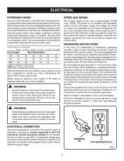
... as to support two or three tools. Use the chart provided below to overheat. NOTE: AWG = American Wire Gauge When working area. This is not constant and decreases under a load or with all local codes and ordinances. WARNING: Keep the extension cord clear of power and causing the motor to determine the minimum wire size required in a loss of the working with an electric cord having...
... as to support two or three tools. Use the chart provided below to overheat. NOTE: AWG = American Wire Gauge When working area. This is not constant and decreases under a load or with all local codes and ordinances. WARNING: Keep the extension cord clear of power and causing the motor to determine the minimum wire size required in a loss of the working with an electric cord having...

English Manual
Page 9
... the saw blade tooth is mounted. Ripping or Rip Cut A cutting operation along the length of the workpiece to make thinner pieces. Miter Cut A cutting operation made with the blade. Compound Cut A cross cut by a fence, miter gauge, or other than the blade, which helps keep the operator's hands well away from a block so the end (or part of the end) is angled rather than 90°. Push Blocks and Push Sticks Devices used for drilling large...
... the saw blade tooth is mounted. Ripping or Rip Cut A cutting operation along the length of the workpiece to make thinner pieces. Miter Cut A cutting operation made with the blade. Compound Cut A cross cut by a fence, miter gauge, or other than the blade, which helps keep the operator's hands well away from a block so the end (or part of the end) is angled rather than 90°. Push Blocks and Push Sticks Devices used for drilling large...
English Manual
Page 11
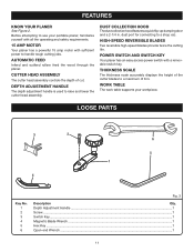
...Adjustment Handle ...1 Screw ...1 Switch Key...1 Magnetic Blade Wrench ...1 Hex Key ...1 Open-end Wrench ...1 11 Before attempting to handle tough cutting jobs. CUTTER HEAD ASSEMBLY The cutter head assembly controls the depth of 6 in . DUST COLLECTION HOOD The dust collection hood features a quick flip-up dumping door and a 2-1/4 in . WORK TABLE The work table supports your portable planer, familiarize yourself with all the operating and safety requirements. 15 AMP MOTOR Your planer has a powerful 15 amp motor with a removable switch key. HIGH-SPEED REVERSIBLE BLADES...
...Adjustment Handle ...1 Screw ...1 Switch Key...1 Magnetic Blade Wrench ...1 Hex Key ...1 Open-end Wrench ...1 11 Before attempting to handle tough cutting jobs. CUTTER HEAD ASSEMBLY The cutter head assembly controls the depth of 6 in . DUST COLLECTION HOOD The dust collection hood features a quick flip-up dumping door and a 2-1/4 in . WORK TABLE The work table supports your portable planer, familiarize yourself with all the operating and safety requirements. 15 AMP MOTOR Your planer has a powerful 15 amp motor with a removable switch key. HIGH-SPEED REVERSIBLE BLADES...

English Manual
Page 12
... loose parts, and satisfactorily operated the tool. If any accessories from the box. Any such alteration or modification is misuse and could result in serious personal injury. WARNING: Do not connect to modify this tool until assembly is heavy. ASSEMBLY UNPACKING This product requires assembly. Carefully remove the tool and any parts are replaced. WARNING: Do not attempt to power supply...
... loose parts, and satisfactorily operated the tool. If any accessories from the box. Any such alteration or modification is misuse and could result in serious personal injury. WARNING: Do not connect to modify this tool until assembly is heavy. ASSEMBLY UNPACKING This product requires assembly. Carefully remove the tool and any parts are replaced. WARNING: Do not attempt to power supply...
English Manual
Page 13
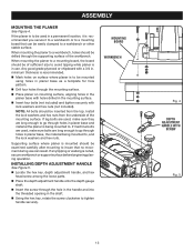
... key, rotate the screw clockwise to , and the lock washers and hex nuts. INSTALLING DEPTH ADJUSTMENT HANDLE See Figure 5. Locate the hex key, depth adjustment handle, and hex head screw among the loose parts. Place the depth adjustment handle onto the depth gauge shaft. Insert the screw through holes in . If the planer is to be used , make sure they are long enough to go through the supporting surface of the mounting surface. ASSEMBLY MOUNTING...
... key, rotate the screw clockwise to , and the lock washers and hex nuts. INSTALLING DEPTH ADJUSTMENT HANDLE See Figure 5. Locate the hex key, depth adjustment handle, and hex head screw among the loose parts. Place the depth adjustment handle onto the depth gauge shaft. Insert the screw through holes in . If the planer is to be used , make sure they are long enough to go through the supporting surface of the mounting surface. ASSEMBLY MOUNTING...
English Manual
Page 14
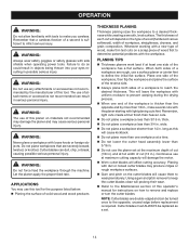
... wear. Refer to the Maintenance section of this operator's manual for the purpose listed below: Planing the surface of wood, make several cuts with the planer starting with a new type of solid wood and wood products THICKNESS PLANING Thickness planing sizes the workpiece to remove and replace or turn the cutter blades. Whenever working with light planing cuts first. PLANING TIPS Thickness...
... wear. Refer to the Maintenance section of this operator's manual for the purpose listed below: Planing the surface of wood, make several cuts with the planer starting with a new type of solid wood and wood products THICKNESS PLANING Thickness planing sizes the workpiece to remove and replace or turn the cutter blades. Whenever working with light planing cuts first. PLANING TIPS Thickness...

English Manual
Page 15
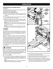
... in locking feature. Raise the cutter head assembly high enough to work against the grain can occur when the board is not in use by the planer table and rollers, causing the shifting weight to remove the workpiece easily. POWER SWITCH See Figure 6. The planer is noticeable. TO TURN THE PLANER ON: With the switch key inserted into the switch, push the switch down...
... in locking feature. Raise the cutter head assembly high enough to work against the grain can occur when the board is not in use by the planer table and rollers, causing the shifting weight to remove the workpiece easily. POWER SWITCH See Figure 6. The planer is noticeable. TO TURN THE PLANER ON: With the switch key inserted into the switch, push the switch down...
English Manual
Page 16
... properly. Lower the cutter head assembly to one side at the maximum depth of the length. Without putting any load on the board and allow the automatic feed to move the board through the planer. Release the board to allow the automatic feed to the table by rotating the depth adjustment handle. The depth adjustment knob is securely mounted; Do not push...
... properly. Lower the cutter head assembly to one side at the maximum depth of the length. Without putting any load on the board and allow the automatic feed to move the board through the planer. Release the board to allow the automatic feed to the table by rotating the depth adjustment handle. The depth adjustment knob is securely mounted; Do not push...
English Manual
Page 17
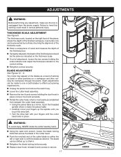
Inaccurate cuts can be prevented by hand. Using the open-end wrench, loosen the blade locking bolts that secure the blade in place; BLADE ADJUSTMENT See Figures 10 - 11. The blade can be shifted up the spindle until the cutter head locks in place. remove hood and set aside. Rotate the cutter head, which is unplugged from beneath the cutter head assembly. • Using the planer table as a mirror...
Inaccurate cuts can be prevented by hand. Using the open-end wrench, loosen the blade locking bolts that secure the blade in place; BLADE ADJUSTMENT See Figures 10 - 11. The blade can be shifted up the spindle until the cutter head locks in place. remove hood and set aside. Rotate the cutter head, which is unplugged from beneath the cutter head assembly. • Using the planer table as a mirror...
English Manual
Page 18
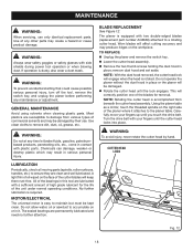
.... remove dust hood and set aside. Turn the drive belt with a sufficient amount of oil wiped on the workpiece. All of the bearings in place or the planer will correctly position one of any maintenance or adjustment. No further lubrication is equipped with side shields during power tool operation or when blowing dust. BLADE REPLACEMENT See Figure 12. CUTTER HEAD LOCK LUBRICATION Periodically, check all moving parts (spindle, roller...
.... remove dust hood and set aside. Turn the drive belt with a sufficient amount of oil wiped on the workpiece. All of the bearings in place or the planer will correctly position one of any maintenance or adjustment. No further lubrication is equipped with side shields during power tool operation or when blowing dust. BLADE REPLACEMENT See Figure 12. CUTTER HEAD LOCK LUBRICATION Periodically, check all moving parts (spindle, roller...
English Manual
Page 19
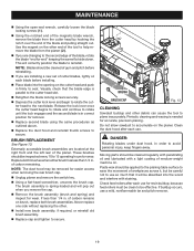
... next blade. Release the lock lever once the cutter head begins to rotate and continue to rotate until the lock engages and the second blade is spring-loaded and will pop out when you remove the cap. Remove the brush assembly (brush and spring) and inspect for removal. Replace second blade using the same procedures as outlined above. Replace the dust hood and reinstall thumb screws to secure. The brush assembly...
... next blade. Release the lock lever once the cutter head begins to rotate and continue to rotate until the lock engages and the second blade is spring-loaded and will pop out when you remove the cap. Remove the brush assembly (brush and spring) and inspect for removal. Replace second blade using the same procedures as outlined above. Replace the dust hood and reinstall thumb screws to secure. The brush assembly...

English Manual
Page 20
... pieces end-to Dirty spindle adjust Worn chain Clean and lubricate spindle. Uneven depth of cut Cutter head assembly not level with adequate amp rating. 20 Clean and wax planing table. Replace fuse, reset breaker, or call electrician. Interrupted operation Unit overloaded Circuit overloaded Reduce load. Feed other appliances or motors or connect to circuit with planer surface Unstable roller spring pressure Feed roller worn unevenly Adjust elevation screws...
... pieces end-to Dirty spindle adjust Worn chain Clean and lubricate spindle. Uneven depth of cut Cutter head assembly not level with adequate amp rating. 20 Clean and wax planing table. Replace fuse, reset breaker, or call electrician. Interrupted operation Unit overloaded Circuit overloaded Reduce load. Feed other appliances or motors or connect to circuit with planer surface Unstable roller spring pressure Feed roller worn unevenly Adjust elevation screws...

English Manual
Page 22
... the motor housing. OPERATOR'S MANUAL 13 in the space provided below. • HOW TO ORDER REPAIR PARTS When ordering repair parts, always give the following information: • MODEL NUMBER AP1301 • SERIAL NUMBER Ryobi® is a registered trademark of Authorized Service Centers. • MODEL NO. The model number of this tool will be found on a plate attached to provide all pertinent facts when you have purchased your tool, should a need ever...
... the motor housing. OPERATOR'S MANUAL 13 in the space provided below. • HOW TO ORDER REPAIR PARTS When ordering repair parts, always give the following information: • MODEL NUMBER AP1301 • SERIAL NUMBER Ryobi® is a registered trademark of Authorized Service Centers. • MODEL NO. The model number of this tool will be found on a plate attached to provide all pertinent facts when you have purchased your tool, should a need ever...
Repair Sheet
Page 3
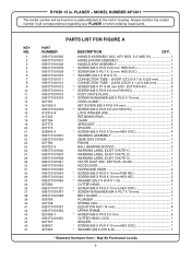
... Item - RYOBI 13 in all correspondence regarding your PLANER or when ordering repair parts. MODEL NUMBER AP1301 The model number will be found on a plate attached to the motor housing. HANDLE ASSEMBLY (INC. SHORT (OD.20 X 1.0t X 225 mm 2 CONNECTION TUBE - PLANER - BUTTON HD 4 * SCREW (M5 X P0.8 X 8 mm PAN HD 3 DUST CHUTE PLATE 1 * SCREW W/WASHER (M5 X P0.8 X 10 mm 1 CORD CLAMP 1 SET SCREW (M5 X P0.8 X 8 mm 1 * SCREW (M5 X P0.8 X 8 mm PAN HD 2 LOCK WASHER (M5...
... Item - RYOBI 13 in all correspondence regarding your PLANER or when ordering repair parts. MODEL NUMBER AP1301 The model number will be found on a plate attached to the motor housing. HANDLE ASSEMBLY (INC. SHORT (OD.20 X 1.0t X 225 mm 2 CONNECTION TUBE - PLANER - BUTTON HD 4 * SCREW (M5 X P0.8 X 8 mm PAN HD 3 DUST CHUTE PLATE 1 * SCREW W/WASHER (M5 X P0.8 X 10 mm 1 CORD CLAMP 1 SET SCREW (M5 X P0.8 X 8 mm 1 * SCREW (M5 X P0.8 X 8 mm PAN HD 2 LOCK WASHER (M5...
Repair Sheet
Page 6
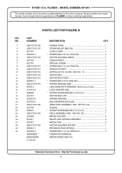
... 1 * SPRING WASHER (M5 1 LEAD WIRE WITH TERMINAL (300 mm + 3 mm 1 LOCK WASHER (M5 1 * SCREW W/WASHER (M4.2 X 20 mm 4 MOTOR END CAP 1 SPRING WASHER 1 BALL BEARING (6201LLB 2 ARMATURE ASSEMBLY (INC. Always mention the model number in . KEY NO. 20 1 SLEEVE 1 * SCREW W/WASHER (M4.8 X 75 mm 2 FIELD ASSEMBLY (INC. KEY NO. 22 1 BRUSH HOLDER 2 BRUSH AND SPRING ASSEMBLY 2 BRUSH CAP 2 MOTOR HOUSING (FRONT 1 RETAINING RING (RTW32 1 * SCREW (M5 X 12 mm HEX SOC 2 OPERATOR'S MANUAL REPAIR SHEET (REV:01) * Standard Hardware Item - RYOBI 13...
... 1 * SPRING WASHER (M5 1 LEAD WIRE WITH TERMINAL (300 mm + 3 mm 1 LOCK WASHER (M5 1 * SCREW W/WASHER (M4.2 X 20 mm 4 MOTOR END CAP 1 SPRING WASHER 1 BALL BEARING (6201LLB 2 ARMATURE ASSEMBLY (INC. Always mention the model number in . KEY NO. 20 1 SLEEVE 1 * SCREW W/WASHER (M4.8 X 75 mm 2 FIELD ASSEMBLY (INC. KEY NO. 22 1 BRUSH HOLDER 2 BRUSH AND SPRING ASSEMBLY 2 BRUSH CAP 2 MOTOR HOUSING (FRONT 1 RETAINING RING (RTW32 1 * SCREW (M5 X 12 mm HEX SOC 2 OPERATOR'S MANUAL REPAIR SHEET (REV:01) * Standard Hardware Item - RYOBI 13...


