Service Manual
Page 1
... SCHEMATIC DIAGRAM 44 » SCHEMATIC DIAGRAM ËR/C, LED Unit ...45 ËMAIN Unit ...46 ËSUB Unit ...60 » PRINTED WIRING BOARD ASSEMBLIES 78 » REPLACEMENT PARTS LIST...95 » PACKING OF THE SET ...109 SHARP CORPORATION This document has been published to be used for after sales service only. The contents are subject to change without notice. LC-13B8U-S LC-15B8U-S LC-15B9U-SM SERVICE MANUAL S55J2LC13B8US LCD COLOR TELEVISION LC-13B8U-S LC-15B8U-S MODELS LC-15B9U...
... SCHEMATIC DIAGRAM 44 » SCHEMATIC DIAGRAM ËR/C, LED Unit ...45 ËMAIN Unit ...46 ËSUB Unit ...60 » PRINTED WIRING BOARD ASSEMBLIES 78 » REPLACEMENT PARTS LIST...95 » PACKING OF THE SET ...109 SHARP CORPORATION This document has been published to be used for after sales service only. The contents are subject to change without notice. LC-13B8U-S LC-15B8U-S LC-15B9U-SM SERVICE MANUAL S55J2LC13B8US LCD COLOR TELEVISION LC-13B8U-S LC-15B8U-S MODELS LC-15B9U...
Service Manual
Page 2
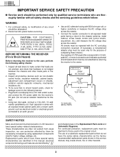
... 10W isolation resistor-capacitor networks, mechanical insulators, etc. 3. BEFORE RETURNING THE RECEIVER (Fire & Shock Hazard) Before returning the receiver to the user, perform the following manner. • Plug the AC cord directly into a 110~240 volt AC outlet, 0.15 µF TEST PROBE and connect the DC power cable into the receiver's DC jack. (Do not use of a substitute replacement parts which must be repeated...
... 10W isolation resistor-capacitor networks, mechanical insulators, etc. 3. BEFORE RETURNING THE RECEIVER (Fire & Shock Hazard) Before returning the receiver to the user, perform the following manner. • Plug the AC cord directly into a 110~240 volt AC outlet, 0.15 µF TEST PROBE and connect the DC power cable into the receiver's DC jack. (Do not use of a substitute replacement parts which must be repeated...
Service Manual
Page 5
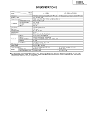
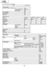
... Video color systems TV Standard (CCIR) TV function TV Tuning System STEREO CATV Y/C FILTER Brightness Viewing angles Audio amplifier Speakers INPUT1 INPUT2 Terminals INPUT3/OUTPUT Antenna Headphone OSD language Power supply Power consumption Weight Display only With Display and stand 13" Advanced Super View & BLACK TFT LCD 15" Advanced Super View & BLACK TFT LCD 921,600 dots VGA N358, N443, PAL, PAL-M, PAL-N, SECAM, PAL-60 NTSC/PAL-M/PAL-N PLL 181 ch. SPECIFICATIONS LC-13B8U-S LC-15B8U-S LC-15B9U...
... Video color systems TV Standard (CCIR) TV function TV Tuning System STEREO CATV Y/C FILTER Brightness Viewing angles Audio amplifier Speakers INPUT1 INPUT2 Terminals INPUT3/OUTPUT Antenna Headphone OSD language Power supply Power consumption Weight Display only With Display and stand 13" Advanced Super View & BLACK TFT LCD 15" Advanced Super View & BLACK TFT LCD 921,600 dots VGA N358, N443, PAL, PAL-M, PAL-N, SECAM, PAL-60 NTSC/PAL-M/PAL-N PLL 181 ch. SPECIFICATIONS LC-13B8U-S LC-15B8U-S LC-15B9U...
Service Manual
Page 6
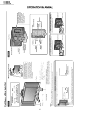
... Security Standard slot* INPUT1 (COMPONENT) INPUT3/ OUTPUT AUDIO (L) Y AUDIO (R) PB PR VIDEO AUDIO (L) AUDIO (R) * Using the Kensington Lock · This LCD TV set can be watched most comfortably. Cable clamp OPERATION MANUAL LC-13B8U-S LC-15B8U-S LC-15B9U-SM w On-screen display Headphones VOLUME 20 Adjust the sound volume using the remote control. Refer to the information that they do not get caught when mounting the cover. 6 Part Names of the Main Unit Controls Upper control panel CH (Channel) ( )/( ) INPUT VOL (Volume) (-)/(+) MENU POWER How to 2.5 degrees...
... Security Standard slot* INPUT1 (COMPONENT) INPUT3/ OUTPUT AUDIO (L) Y AUDIO (R) PB PR VIDEO AUDIO (L) AUDIO (R) * Using the Kensington Lock · This LCD TV set can be watched most comfortably. Cable clamp OPERATION MANUAL LC-13B8U-S LC-15B8U-S LC-15B9U-SM w On-screen display Headphones VOLUME 20 Adjust the sound volume using the remote control. Refer to the information that they do not get caught when mounting the cover. 6 Part Names of the Main Unit Controls Upper control panel CH (Channel) ( )/( ) INPUT VOL (Volume) (-)/(+) MENU POWER How to 2.5 degrees...

Service Manual
Page 7
... VIDEO INPUT mode is compatible with new "AAA" size batteries. 1 Open the battery cover. 2 Insert two "AAA" size batteries. 3 Close the battery cover. Cautions regarding batteries s Improper use of the remote control s Do not apply shock to the country before using the LCD TV set . DISPLAY Displays the receiving channel and the current time for the first time, install the two "AAA" size batteries supplied in a leakage of chemicals and/or explosion. INPUT Switches the input source...
... VIDEO INPUT mode is compatible with new "AAA" size batteries. 1 Open the battery cover. 2 Insert two "AAA" size batteries. 3 Close the battery cover. Cautions regarding batteries s Improper use of the remote control s Do not apply shock to the country before using the LCD TV set . DISPLAY Displays the receiving channel and the current time for the first time, install the two "AAA" size batteries supplied in a leakage of chemicals and/or explosion. INPUT Switches the input source...
Service Manual
Page 13
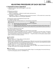
... (initialization) → Setting the model number and screen size 1-2. Preparations before adjustment (1) Keep the AC power cable directly plugged in the checker mode (EEPROM still brand-new after the checker mode) L L EEPROM initialized and microprocessor's master settings written (process adjustment values not yet written) 2-2. Calling the adjustment process mode There are two ways to adjustment process mode H L Operation with master ROM settings in a wall outlet. Finishing process adjustments Assembling → Power on the...
... (initialization) → Setting the model number and screen size 1-2. Preparations before adjustment (1) Keep the AC power cable directly plugged in the checker mode (EEPROM still brand-new after the checker mode) L L EEPROM initialized and microprocessor's master settings written (process adjustment values not yet written) 2-2. Calling the adjustment process mode There are two ways to adjustment process mode H L Operation with master ROM settings in a wall outlet. Finishing process adjustments Assembling → Power on the...
Service Manual
Page 14
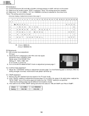
CH I C MOD E OFF 5 V - Model Setting LC-13B8U 155-158 LC-15B8/B9U 155-158 14 TAMP adjustment 1) Receive the 75% standard color bar signal in the TV input mode. 2) If the "YDATA" reading on the power. 4-2. Make sure "13" (LC-13B8U), "15" (LC-15B8/B9U) (inches) is selected for "PAL-M TAMP" and "PAL-N TAMP". With the setting changed . (Onscreen display of adjustment process menu page 1) 0 1 2 3 4 5 6 7 8 9 10 11 12 13 14 15 16 17...
CH I C MOD E OFF 5 V - Model Setting LC-13B8U 155-158 LC-15B8/B9U 155-158 14 TAMP adjustment 1) Receive the 75% standard color bar signal in the TV input mode. 2) If the "YDATA" reading on the power. 4-2. Make sure "13" (LC-13B8U), "15" (LC-15B8/B9U) (inches) is selected for "PAL-M TAMP" and "PAL-N TAMP". With the setting changed . (Onscreen display of adjustment process menu page 1) 0 1 2 3 4 5 6 7 8 9 10 11 12 13 14 15 16 17...
Service Manual
Page 15
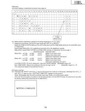
... the factory settings have been made, turn on , the set to malfunction.) SETTING COMPLETE 15 Inspection spec. Adjustable range ±30. Adjustable range 0 to 10 lx or less.) 1) Adjustment procedure (Call the AV input mode with INPUT3 or INPUT4.) Adjust the RGB CUTOFF2 setting for the 40% white level, and the RGB-GAIN setting for the white 80% level. (1) Adjustment [Input signal] White 80% (191 gradations) and white 40% (92 gradations) signals [Adjustment value...
... the factory settings have been made, turn on , the set to malfunction.) SETTING COMPLETE 15 Inspection spec. Adjustable range ±30. Adjustable range 0 to 10 lx or less.) 1) Adjustment procedure (Call the AV input mode with INPUT3 or INPUT4.) Adjust the RGB CUTOFF2 setting for the 40% white level, and the RGB-GAIN setting for the white 80% level. (1) Adjustment [Input signal] White 80% (191 gradations) and white 40% (92 gradations) signals [Adjustment value...
Service Manual
Page 16
... ON ON 2ch TV 2ch 20 DYNAMIC OFF BRIGHT (17) 40 0 5 0 0 MIDDLE 0 0 0 0 0 0 STANDARD OFF BRIGHT 30 0 0 0 0 MOVIE OFF 7 30 0 0 0 0 GAME OFF NORMAL (9) 30 0 0 0 0 MENU-SETUP CH-SETTING MTS CLOCK INPUT3 SELECT V-CHIP BLOCK CLOSED CAPTION COLOR SYSTEM (TV) COLOR SYSTEM (INPUT2,3) LANGUAGE MENU-OPTION VIEW MODE AUDIO ONLY BLUE SCREEN SLEEP TIMER WAKEUP TIMER NO SIGNAL OFF NO OPERATION OFF PICTURE FLIP AIR/CABLE CH MEMORY SET TIME DISPLAY INPUT SECRET NO. LC-13B8U-S LC-15B8U-S LC-15B9U-SM 6-2. ENGLISH...
... ON ON 2ch TV 2ch 20 DYNAMIC OFF BRIGHT (17) 40 0 5 0 0 MIDDLE 0 0 0 0 0 0 STANDARD OFF BRIGHT 30 0 0 0 0 MOVIE OFF 7 30 0 0 0 0 GAME OFF NORMAL (9) 30 0 0 0 0 MENU-SETUP CH-SETTING MTS CLOCK INPUT3 SELECT V-CHIP BLOCK CLOSED CAPTION COLOR SYSTEM (TV) COLOR SYSTEM (INPUT2,3) LANGUAGE MENU-OPTION VIEW MODE AUDIO ONLY BLUE SCREEN SLEEP TIMER WAKEUP TIMER NO SIGNAL OFF NO OPERATION OFF PICTURE FLIP AIR/CABLE CH MEMORY SET TIME DISPLAY INPUT SECRET NO. LC-13B8U-S LC-15B8U-S LC-15B9U-SM 6-2. ENGLISH...
Service Manual
Page 18
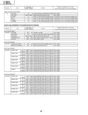
... SETTING (WITH TV INPUT) NOT USED EQUALIZER SETTING (WITH OTHER INPUT THAN TV) NOT USED 18 I2C BUS CONTROL IC DATA WRITE AND READ WRITE AND READ EXECUTED SHIFT TO THE SOUND ADJUSTMENT PAGE SHIFT TO THE DVP ADJUSTMENT PAGE SHIFT TO THE TUNER ADJUSTMENT PAGE SHIFT TO THE OTHER ADJUSTMENT PAGE NOT USED NOT USED USE ENTER KEY TO GO TO THE SOUND ADJUSTMENT PAGE. AUDIO ADJUSTMENT PROCESS SPECIFICATIONS Page No. Item TABLE...
... SETTING (WITH TV INPUT) NOT USED EQUALIZER SETTING (WITH OTHER INPUT THAN TV) NOT USED 18 I2C BUS CONTROL IC DATA WRITE AND READ WRITE AND READ EXECUTED SHIFT TO THE SOUND ADJUSTMENT PAGE SHIFT TO THE DVP ADJUSTMENT PAGE SHIFT TO THE TUNER ADJUSTMENT PAGE SHIFT TO THE OTHER ADJUSTMENT PAGE NOT USED NOT USED USE ENTER KEY TO GO TO THE SOUND ADJUSTMENT PAGE. AUDIO ADJUSTMENT PROCESS SPECIFICATIONS Page No. Item TABLE...
Service Manual
Page 20
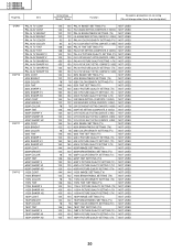
... SHARP V 750P SHARP H1 750P SHARP H2 Initial Value 13inch 15inch Function Response precautions on servicing (Do not change other items than designated.) 144 144 PAL-N IMAGE SETTING (TV) NOT USED 144 144 PAL-N IMAGE SETTING (COMPOSITE, S VIDEO) NOT USED 122 122 PAL-N BRIGHTNESS SETTING (TV) NOT USED 122 122 PAL-N BRIGHTNESS SETTING (COMPOSITE, S VIDEO) NOT USED 52 52 PAL-N COLOR DENSITY SETTING (TV) NOT USED 52 52 PAL-N COLOR DENSITY SETTING (COMPOSITE, S VIDEO...
... SHARP V 750P SHARP H1 750P SHARP H2 Initial Value 13inch 15inch Function Response precautions on servicing (Do not change other items than designated.) 144 144 PAL-N IMAGE SETTING (TV) NOT USED 144 144 PAL-N IMAGE SETTING (COMPOSITE, S VIDEO) NOT USED 122 122 PAL-N BRIGHTNESS SETTING (TV) NOT USED 122 122 PAL-N BRIGHTNESS SETTING (COMPOSITE, S VIDEO) NOT USED 52 52 PAL-N COLOR DENSITY SETTING (TV) NOT USED 52 52 PAL-N COLOR DENSITY SETTING (COMPOSITE, S VIDEO...
Service Manual
Page 21
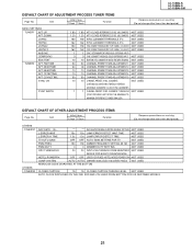
... USED PWM DUTY 0 0 DIMMER DUTY SETTING NOT USED OPC THRESHOLD 24 24 INPUT LEVEL THRESHOLD FROM BRIGHTNESS NOT USED SENSOR STOP MODE TO OPERATION MODE HOTEL POWERFIX OFF OFF USED FOR FIXED HOTEL MODE POWER ON NOT USED COMP SYSTEM AUTO AUTO COMPONENT SIGNAL SELECT IN ADJUSTMENT PROCESS NOT USED REMOCON CODE DISPLAYED AT THE BOTTOM CLOSED CAPTION 15 15 CLOSED CAPTION THRESH LEVEL NOT USED AUTO CLOCK DISPLAYED ON THE 2ND, 3RD AND 4TH LINES FROM BOTTOM FOR US-DESTINED MODELS...
... USED PWM DUTY 0 0 DIMMER DUTY SETTING NOT USED OPC THRESHOLD 24 24 INPUT LEVEL THRESHOLD FROM BRIGHTNESS NOT USED SENSOR STOP MODE TO OPERATION MODE HOTEL POWERFIX OFF OFF USED FOR FIXED HOTEL MODE POWER ON NOT USED COMP SYSTEM AUTO AUTO COMPONENT SIGNAL SELECT IN ADJUSTMENT PROCESS NOT USED REMOCON CODE DISPLAYED AT THE BOTTOM CLOSED CAPTION 15 15 CLOSED CAPTION THRESH LEVEL NOT USED AUTO CLOCK DISPLAYED ON THE 2ND, 3RD AND 4TH LINES FROM BOTTOM FOR US-DESTINED MODELS...
Service Manual
Page 22
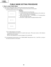
... other passwords, the screen changes to the right. » With all the 3 digits entered, the password will move one digit to the normal mode. 2 In the adjustment process mode, turn on the remote controller. The input position will be verified. 3) The 3-digit password is now verified. LC-13B8U-S LC-15B8U-S LC-15B9U-SM PUBLIC MODE SETTING PROCEDURE 1. The password [0] [2] [7] provides for the public mode screen. (This screen comes on with the leftmost digit. » Use the numeric...
... other passwords, the screen changes to the right. » With all the 3 digits entered, the password will move one digit to the normal mode. 2 In the adjustment process mode, turn on the remote controller. The input position will be verified. 3) The 3-digit password is now verified. LC-13B8U-S LC-15B8U-S LC-15B9U-SM PUBLIC MODE SETTING PROCEDURE 1. The password [0] [2] [7] provides for the public mode screen. (This screen comes on with the leftmost digit. » Use the numeric...

Service Manual
Page 23
... the factory settings made, the public mode settings get initialized. (The adjustment process remains intact.) 4. Public mode Maximum volume Volume fixed Volume fixed level RC button Panel button Menu button On screen display Input mode start Input mode fixed Reset Enter [ 60 ] [Variable ] [ 20 ] [Respond ] [Respond ] [Respond ] [Yes ] [Normal ] [Variable ] 23 Setup procedure » To move the cursor up and down, use the "cursor UP/DOWN" key (remote controller) and "CH (ù)/(Ù)" key (remote controller and set). » To change the settings, use...
... the factory settings made, the public mode settings get initialized. (The adjustment process remains intact.) 4. Public mode Maximum volume Volume fixed Volume fixed level RC button Panel button Menu button On screen display Input mode start Input mode fixed Reset Enter [ 60 ] [Variable ] [ 20 ] [Respond ] [Respond ] [Respond ] [Yes ] [Normal ] [Variable ] 23 Setup procedure » To move the cursor up and down, use the "cursor UP/DOWN" key (remote controller) and "CH (ù)/(Ù)" key (remote controller and set). » To change the settings, use...

Service Manual
Page 26
Ex.) Screen display, menu, OFF-timer, ON-timer, AV MODE, screen size switching, clock setting, treble emphasis, AUDIO ONLY, sound changeover, LANGUAGE, CLOSED CAPTION » Simple input switching is . Non-responding signal caution, V-Chip caution and power-ON fixing caution » In "No" setting, the setting of "SOUND ONLY MODE" is changed to "OFF" and selecting operation is made prohibited. » When CC has already been ON, CLOSED CAPTION is displayed. (8) INPUT MODE START Selection Selection between "Normal" , "TV (CH~)" "COMPONENT" "AV1" and...
Ex.) Screen display, menu, OFF-timer, ON-timer, AV MODE, screen size switching, clock setting, treble emphasis, AUDIO ONLY, sound changeover, LANGUAGE, CLOSED CAPTION » Simple input switching is . Non-responding signal caution, V-Chip caution and power-ON fixing caution » In "No" setting, the setting of "SOUND ONLY MODE" is changed to "OFF" and selecting operation is made prohibited. » When CC has already been ON, CLOSED CAPTION is displayed. (8) INPUT MODE START Selection Selection between "Normal" , "TV (CH~)" "COMPONENT" "AV1" and...

Service Manual
Page 27
... Are the waveforms at the signal input pins of IC2001 Note: This model is detected, the microprocessor interrupts the unit and the ERROR NO RESET setting will go up. TV/Composite ... Is the power turned on it (to reset to ERROR NO RESET and click on again? Check IC801 and its peripheral circuits. 1 MODEL INCH SIZE ERROR NO RESET PUBLIC MODE V-CHIP EXT CONTROL A629 ~ 0 OFF 1 OFF VER ROM...
... Are the waveforms at the signal input pins of IC2001 Note: This model is detected, the microprocessor interrupts the unit and the ERROR NO RESET setting will go up. TV/Composite ... Is the power turned on it (to reset to ERROR NO RESET and click on again? Check IC801 and its peripheral circuits. 1 MODEL INCH SIZE ERROR NO RESET PUBLIC MODE V-CHIP EXT CONTROL A629 ~ 0 OFF 1 OFF VER ROM...
Service Manual
Page 28
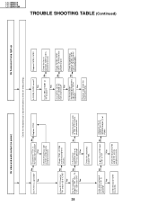
... the connecting cable. Check the load of T701 +5V, -7V, -12V, +35V and +9V? Are the secondary No outputs of IC702 and IC701 and its peripheral circuits. Yes Check the peripheral parts of IC703? Yes Disconnect F7701. Is there DC 12V input at... SC2003 and pin (2) of IC701 thru IC703. Replace and check the fluorescent lamp. Yes Yes Check the load of P3404. LC-13B8U-S LC-15B8U-S LC-15B9U-SM No video and audio output (no power) No fluorescent lamp light-up TROUBLE SHOOTING TABLE (Continued) Check the microprocessor's adjustment process menu for wrong settings.
... the connecting cable. Check the load of T701 +5V, -7V, -12V, +35V and +9V? Are the secondary No outputs of IC702 and IC701 and its peripheral circuits. Yes Check the peripheral parts of IC703? Yes Disconnect F7701. Is there DC 12V input at... SC2003 and pin (2) of IC701 thru IC703. Replace and check the fluorescent lamp. Yes Yes Check the load of P3404. LC-13B8U-S LC-15B8U-S LC-15B9U-SM No video and audio output (no power) No fluorescent lamp light-up TROUBLE SHOOTING TABLE (Continued) Check the microprocessor's adjustment process menu for wrong settings.

Service Manual
Page 29
... Check IC3401 and its input line and peripheral parts. No Is the output of the LCD its peripheral IC3401 as specified? No Input 3 pictures come out? TROUBLE SHOOTING TABLE (Continued) Does the No Check test pattern IC801 and of IC8701 as peripheral specified? specified? tuner as specified? specified? parts of IC801, the input and their peripheral parts. 29 LC-13B8U-S LC-15B8U-S LC-15B9U-SM No Are...
... Check IC3401 and its input line and peripheral parts. No Is the output of the LCD its peripheral IC3401 as specified? No Input 3 pictures come out? TROUBLE SHOOTING TABLE (Continued) Does the No Check test pattern IC801 and of IC8701 as peripheral specified? specified? tuner as specified? specified? parts of IC801, the input and their peripheral parts. 29 LC-13B8U-S LC-15B8U-S LC-15B9U-SM No Are...

Service Manual
Page 30
... as specified? Do the following . Is the audio signal outputted from J3405 to "Sound Fixed" or "Sound Variable"? 2Is the sound volume level sufficient? 3Is the muting effect turned off the muting effect. No Check the input line and its peripheral parts. Yes Perform the following checking. 1No TV sounds come out from the speakers". 2Connect the monitor output properly. 3Turn off ? 4Are the headphones disconnected...
... as specified? Do the following . Is the audio signal outputted from J3405 to "Sound Fixed" or "Sound Variable"? 2Is the sound volume level sufficient? 3Is the muting effect turned off the muting effect. No Check the input line and its peripheral parts. Yes Perform the following checking. 1No TV sounds come out from the speakers". 2Connect the monitor output properly. 3Turn off ? 4Are the headphones disconnected...

Service Manual
Page 106
... PARTS (LC-15B8U-S, LC-15B9U-SM) 1 CCABAA939WJ05 X Cabinet A Ass'y BH (LC-15B8U-S) 1 CCABAA939WJ04 X Cabinet A Ass'y BK (LC-15B9U-SM) 1-1 Not Available - No. Cabinet B - CBTN-A444WJ02 X Operation Button Ass'y AM Not Available - RLCDTA024WJN1 J 15" LCD Panel Unit CN Not Available - Back Shield Ass'y - No. Part No. 5 Description 15 QCNW-D738WJQZ X Connecting Cord 16 QCNW-D897WJQZ X Connecting Cord 17 QCNW-D898WJQZ X Connecting Cord 18 QCNW-D899WJQZ X Connecting Cord 19 VSP7040PB658S J Speaker, x2 20 LX-BZ3442CEF9 J Screw...
... PARTS (LC-15B8U-S, LC-15B9U-SM) 1 CCABAA939WJ05 X Cabinet A Ass'y BH (LC-15B8U-S) 1 CCABAA939WJ04 X Cabinet A Ass'y BK (LC-15B9U-SM) 1-1 Not Available - No. Cabinet B - CBTN-A444WJ02 X Operation Button Ass'y AM Not Available - RLCDTA024WJN1 J 15" LCD Panel Unit CN Not Available - Back Shield Ass'y - No. Part No. 5 Description 15 QCNW-D738WJQZ X Connecting Cord 16 QCNW-D897WJQZ X Connecting Cord 17 QCNW-D898WJQZ X Connecting Cord 18 QCNW-D899WJQZ X Connecting Cord 19 VSP7040PB658S J Speaker, x2 20 LX-BZ3442CEF9 J Screw...


