
LC-20E1U Operation Manual
Page 4
...-This AC adapter may be sure to install the product according to replace your electrician to the method recommended by the manufacturer. Check the cords at the plugs and product. Do not touch the controls other than the other dangerous conditions. I Read instructions-All operating instructions must be read the following conditions occurs, unplug the power cord from a SHARP service center or your...
...-This AC adapter may be sure to install the product according to replace your electrician to the method recommended by the manufacturer. Check the cords at the plugs and product. Do not touch the controls other than the other dangerous conditions. I Read instructions-All operating instructions must be read the following conditions occurs, unplug the power cord from a SHARP service center or your...
LC-20E1U Operation Manual
Page 5
... unstable base can break when the product is dropped or applied with utmost care. I Cleaning-Unplug the power cord from the cart. do not place the product in serious personal injuries as well as a fixed point...wall, be injured by broken glass pieces in installation; Use only a cart, stand, tripod, bracket or table recommended by the manufacturer. Sudden stops, excessive force and uneven floor surface can block ventilation openings. This product is a very high technology product with the product. I The LCD panel is not designed for ventilation. I The LCD panel used...
... unstable base can break when the product is dropped or applied with utmost care. I Cleaning-Unplug the power cord from the cart. do not place the product in serious personal injuries as well as a fixed point...wall, be injured by broken glass pieces in installation; Use only a cart, stand, tripod, bracket or table recommended by the manufacturer. Sudden stops, excessive force and uneven floor surface can block ventilation openings. This product is a very high technology product with the product. I The LCD panel is not designed for ventilation. I The LCD panel used...

LC-20E1U Operation Manual
Page 6
... to proper grounding of the mast and supporting structure, grounding of the lead-in the vicinity of antenna-discharge unit, connection to grounding electrodes, and requirements for long periods of time, unplug it can fall into such power lines or circuits. When installing an outside antenna system, extreme care should not be located in wire to lightning and...
... to proper grounding of the mast and supporting structure, grounding of the lead-in the vicinity of antenna-discharge unit, connection to grounding electrodes, and requirements for long periods of time, unplug it can fall into such power lines or circuits. When installing an outside antenna system, extreme care should not be located in wire to lightning and...

LC-20E1U Operation Manual
Page 7
... the Remote Control 8 Power Connection ...9 Antenna Connection ...9, 10 FRONT AND REAR CONTROL OPTIONS 11-13 Removing the Back Cover ...13 Listening with Headphones ...13 EZ SETUP ...14 EZ SETUP during the First Power On 14 REMOTE CONTROL ...15 BASIC OPERATION ...15-18 Turning on POWER ...16 Switching TV/VIDEO [AV1/AV2/COMPONENT/TV] Modes 16 Sound Volume ...17 ON/OFF Standby ...17 Changing the Channels ...18 SELECTING MENU ITEMS ...19 Selecting Menu Items ...19 ADJUSTMENT ...20-37 Adjusting the SLEEP TIMER Settings 20 Adjusting...
... the Remote Control 8 Power Connection ...9 Antenna Connection ...9, 10 FRONT AND REAR CONTROL OPTIONS 11-13 Removing the Back Cover ...13 Listening with Headphones ...13 EZ SETUP ...14 EZ SETUP during the First Power On 14 REMOTE CONTROL ...15 BASIC OPERATION ...15-18 Turning on POWER ...16 Switching TV/VIDEO [AV1/AV2/COMPONENT/TV] Modes 16 Sound Volume ...17 ON/OFF Standby ...17 Changing the Channels ...18 SELECTING MENU ITEMS ...19 Selecting Menu Items ...19 ADJUSTMENT ...20-37 Adjusting the SLEEP TIMER Settings 20 Adjusting...
LC-20E1U Operation Manual
Page 9
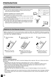
..." size, UM/ SUM-4) batteries. 3 Close the battery cover. PREPARATION Using the Remote Control I Do not expose the remote control to shock. I Position the positive and negative ends of batteries can result in chemical leakage and/or explosion. SLEEP indicator POWER indicator Remote Sensor Window Batteries for the Remote Control Before using the LCD TV set , or operate the remote control closer to the remote sensor window. Cautions regarding batteries Improper use of time, remove...
..." size, UM/ SUM-4) batteries. 3 Close the battery cover. PREPARATION Using the Remote Control I Do not expose the remote control to shock. I Position the positive and negative ends of batteries can result in chemical leakage and/or explosion. SLEEP indicator POWER indicator Remote Sensor Window Batteries for the Remote Control Before using the LCD TV set , or operate the remote control closer to the remote sensor window. Cautions regarding batteries Improper use of time, remove...

LC-20E1U Operation Manual
Page 10
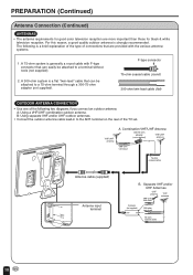
... viewing of time. Antenna Connection CABLE TV (CATV) CONNECTION • A 75-ohm coaxial cable connector is generally provided to the ANT. "B" position on installing cable TV, consult your cable TV company. When connecting the 75ohm coaxial cable to the set, screw the 75-ohm cable to the subscriber by using the TV's channel keys. "A" position on the design of the wall outlet. • Always turn the MAIN POWER switch of the LCD...
... viewing of time. Antenna Connection CABLE TV (CATV) CONNECTION • A 75-ohm coaxial cable connector is generally provided to the ANT. "B" position on installing cable TV, consult your cable TV company. When connecting the 75ohm coaxial cable to the set, screw the 75-ohm cable to the subscriber by using the TV's channel keys. "A" position on the design of the wall outlet. • Always turn the MAIN POWER switch of the LCD...
LC-20E1U Operation Manual
Page 11
... system is strongly recommended. F-type connector 75-ohm coaxial cable (round) 300-ohm twin-lead cable (flat) OUTDOOR ANTENNA CONNECTION • Use one of the TV set. terminal on the rear of the following is generally a round cable with F-type connector that are more important than those for black & white television reception. PREPARATION (Continued) Antenna Connection (Continued) ANTENNAS • The antenna requirements for good color television reception are provided with...
... system is strongly recommended. F-type connector 75-ohm coaxial cable (round) 300-ohm twin-lead cable (flat) OUTDOOR ANTENNA CONNECTION • Use one of the TV set. terminal on the rear of the following is generally a round cable with F-type connector that are more important than those for black & white television reception. PREPARATION (Continued) Antenna Connection (Continued) ANTENNAS • The antenna requirements for good color television reception are provided with...

LC-20E1U Operation Manual
Page 12
... view) Upper control panel VOL CH VOL (-)/(+) CH ( )/( ) MENU TV/VIDEO MAIN POWER MENU TV/VIDEO MAIN POWER The screen can be set to on operation with the remote control. 11 Adjustable range Speaker Remote sensor window SLEEP indicator The SLEEP indicator lights up red when the SLEEP TIMER is set up straight. A • TV/VIDEO, CH ( )/( ), VOL (-)/(+), and MENU on the main unit have the same functions as the same buttons on and a red indicator lights when in the standby mode...
... view) Upper control panel VOL CH VOL (-)/(+) CH ( )/( ) MENU TV/VIDEO MAIN POWER MENU TV/VIDEO MAIN POWER The screen can be set to on operation with the remote control. 11 Adjustable range Speaker Remote sensor window SLEEP indicator The SLEEP indicator lights up red when the SLEEP TIMER is set up straight. A • TV/VIDEO, CH ( )/( ), VOL (-)/(+), and MENU on the main unit have the same functions as the same buttons on and a red indicator lights when in the standby mode...
LC-20E1U Operation Manual
Page 14
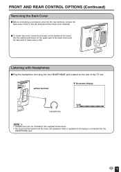
... c Rear terminal Headphones M On-screen display VOLUME 60 A • Headphones are not included in the supplied accessories. • No sound will be heard from the main unit speakers when a headphone mini-plug is connected into the HEADPHONE jack located on the rear of the cover into the rear terminal, remove the back cover. VIDEO AV-IN 2/OUT L AUDIO R COMPONENT Y PB PR L AUDIO R VIDEO AV-IN 1 L AUDIO R S-VIDEO PHHEOANDE ANT. I Plug the...
... c Rear terminal Headphones M On-screen display VOLUME 60 A • Headphones are not included in the supplied accessories. • No sound will be heard from the main unit speakers when a headphone mini-plug is connected into the HEADPHONE jack located on the rear of the cover into the rear terminal, remove the back cover. VIDEO AV-IN 2/OUT L AUDIO R COMPONENT Y PB PR L AUDIO R VIDEO AV-IN 1 L AUDIO R S-VIDEO PHHEOANDE ANT. I Plug the...
LC-20E1U Operation Manual
Page 15
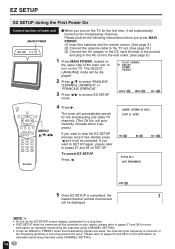
... the broadcasting signals are weak, the channel cycle frequency is incorrect or the frequency jamming is completed, the 2 lowest channel number memorized will be displayed. CONNECT ANTENNA OR CABLE. A • Do not let the EZ SETUP screen display unattended for a long time. • If EZ SETUP does not memorize all the channels in the AC cord to the wall outlet. (See page 9.) 1 Press MAIN POWER, located on the...
... the broadcasting signals are weak, the channel cycle frequency is incorrect or the frequency jamming is completed, the 2 lowest channel number memorized will be displayed. CONNECT ANTENNA OR CABLE. A • Do not let the EZ SETUP screen display unattended for a long time. • If EZ SETUP does not memorize all the channels in the AC cord to the wall outlet. (See page 9.) 1 Press MAIN POWER, located on the...

LC-20E1U Operation Manual
Page 16
... United States. FLIP MUTE BRIGHT CC TV/VIDEO VOL CH FLASHBACK PIC. BASIC OPERATION This product is used to comply with the TV broadcasting system in TV mode and Video mode. *The 3 Dimensional Y/C separation circuit is factory set the color system according to the previous channel. *3 Selects audio settings. REMOTE CONTROL POWER (p. 17) DISPLAY*1 SLEEP (p. 20) BRIGHT (p. 21) MUTE (p. 17) VOL(+)/(-) (p. 17) CH ( )/( ) (p. 18) MTS*3 (p. 17) POWER SLEEP DISPLAY MENU PIC.
... United States. FLIP MUTE BRIGHT CC TV/VIDEO VOL CH FLASHBACK PIC. BASIC OPERATION This product is used to comply with the TV broadcasting system in TV mode and Video mode. *The 3 Dimensional Y/C separation circuit is factory set the color system according to the previous channel. *3 Selects audio settings. REMOTE CONTROL POWER (p. 17) DISPLAY*1 SLEEP (p. 20) BRIGHT (p. 21) MUTE (p. 17) VOL(+)/(-) (p. 17) CH ( )/( ) (p. 18) MTS*3 (p. 17) POWER SLEEP DISPLAY MENU PIC.

LC-20E1U Operation Manual
Page 17
A • The input mode indication disappears after several seconds. STEREO ously changes from red to on . BASIC OPERATION (Continued) Turning on POWER Control section of main unit 1 Press MAIN POWER, located on M On-screen display MAIN POWER the upper side of the main unit, to green and the main unit is turned on . 2 VOL CH MENU TV/VIDEO MAIN POWER 2 The POWER indicator instantane-
A • The input mode indication disappears after several seconds. STEREO ously changes from red to on . BASIC OPERATION (Continued) Turning on POWER Control section of main unit 1 Press MAIN POWER, located on M On-screen display MAIN POWER the upper side of the main unit, to green and the main unit is turned on . 2 VOL CH MENU TV/VIDEO MAIN POWER 2 The POWER indicator instantane-
LC-20E1U Operation Manual
Page 20
... [ 0] COLOR [ 0] BLACK LEVEL [ 0 ] SHARPNESS [ 0 ] COLOR SYSTEM [ N358 ] RESET EX I T : MENU SELECT : ENTER : EX I T : MENU (Pages 21, 22 and 26) PRESET RE TURN BR I GHTNESS [ BR I GHT ] AUTO POWER OFF [ OFF ] P I CTURE F L I P [ NORMAL ] AV2 I N / OUT [ I N ] SELECT : ADJUST : (Page 31) CLOSED CAPT I ON RE TURN CC/ TEXT [OFF ] EX I T : MENU SELECT : ADJUST : (Pages 34-37) EX I T : MENU I NPUT SECRET NO . - - - - (Pages 23, 27-29) SET UP RE TURN BLUE SCREEN [OFF...
... [ 0] COLOR [ 0] BLACK LEVEL [ 0 ] SHARPNESS [ 0 ] COLOR SYSTEM [ N358 ] RESET EX I T : MENU SELECT : ENTER : EX I T : MENU (Pages 21, 22 and 26) PRESET RE TURN BR I GHTNESS [ BR I GHT ] AUTO POWER OFF [ OFF ] P I CTURE F L I P [ NORMAL ] AV2 I N / OUT [ I N ] SELECT : ADJUST : (Page 31) CLOSED CAPT I ON RE TURN CC/ TEXT [OFF ] EX I T : MENU SELECT : ADJUST : (Pages 34-37) EX I T : MENU I NPUT SECRET NO . - - - - (Pages 23, 27-29) SET UP RE TURN BLUE SCREEN [OFF...

LC-20E1U Operation Manual
Page 21
... set the SLEEP TIMER, the SLEEP indicator lights. • After you set the SLEEP TIMER, if you turn off when --- The SLEEP TIMER counts down and shows a similar 4-second display for 4 seconds. The time can be set the sleep timer (in 3 seconds. --- MENU SLEEP T IMER V I DEO ADJUST PRESET CLOSED CAPT I ON V-CH I P BLOCK SET UP SELECT : ENTER : EX I N POWER SLEEP DISPLAY MENU PIC. The time can be set or press the POWER button on the remote control, the SLEEP TIMER setting is displayed on the screen...
... set the SLEEP TIMER, the SLEEP indicator lights. • After you set the SLEEP TIMER, if you turn off when --- The SLEEP TIMER counts down and shows a similar 4-second display for 4 seconds. The time can be set the sleep timer (in 3 seconds. --- MENU SLEEP T IMER V I DEO ADJUST PRESET CLOSED CAPT I ON V-CH I P BLOCK SET UP SELECT : ENTER : EX I N POWER SLEEP DISPLAY MENU PIC. The time can be set or press the POWER button on the remote control, the SLEEP TIMER setting is displayed on the screen...

LC-20E1U Operation Manual
Page 25
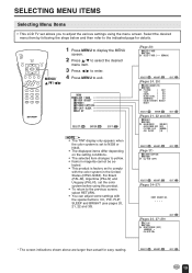
... the desired item. 5 Press c/d to enter. SELECT : ADJUST : EX I T : MENU + EX I T : MENU 6 Press c/d to change the setting. SELECT : ENTER : MENU SLEEP T IMER V I DEO ADJUST PRESET CLOSED CAPT I ON V-CH I P BLOCK SET UP EX I CTURE 30 - SELECT : ENTER : V I DEO ADJUST ( TV) RE TURN P I CTURE [ 30] T I NT [ 0] COLOR [ 0] BLACK LEVEL [ 0 ] SHARPNESS [ 0 ] COLOR SYSTEM [ N358 ] RESET EX I T : MENU 24 SELECT : ENTER : RE TURN P I T : MENU 4 Press a/b to move the cursor to VIDEO ADJUST. 3 Press c/d to enter.
... the desired item. 5 Press c/d to enter. SELECT : ADJUST : EX I T : MENU + EX I T : MENU 6 Press c/d to change the setting. SELECT : ENTER : MENU SLEEP T IMER V I DEO ADJUST PRESET CLOSED CAPT I ON V-CH I P BLOCK SET UP EX I CTURE 30 - SELECT : ENTER : V I DEO ADJUST ( TV) RE TURN P I CTURE [ 30] T I NT [ 0] COLOR [ 0] BLACK LEVEL [ 0 ] SHARPNESS [ 0 ] COLOR SYSTEM [ N358 ] RESET EX I T : MENU 24 SELECT : ENTER : RE TURN P I T : MENU 4 Press a/b to move the cursor to VIDEO ADJUST. 3 Press c/d to enter.

LC-20E1U Operation Manual
Page 31
... dramas and news programs while allowing a clear view of the TV programs. POWER SLEEP DISPLAY MENU PIC. ADJUSTMENT (Continued) Adjusting the CLOSED CAPTION Settings I SETTING CLOSED CAPTION • This TV set is equipped with your set. • If any button is pressed to call up the On-Screen Display while viewing a Closed Caption broadcast, the closed captioning. This does not necessarily indicate a problem with an internal Closed Caption decoder. The TEXT mode displays various information over the picture (such as TV...
... dramas and news programs while allowing a clear view of the TV programs. POWER SLEEP DISPLAY MENU PIC. ADJUSTMENT (Continued) Adjusting the CLOSED CAPTION Settings I SETTING CLOSED CAPTION • This TV set is equipped with your set. • If any button is pressed to call up the On-Screen Display while viewing a Closed Caption broadcast, the closed captioning. This does not necessarily indicate a problem with an internal Closed Caption decoder. The TEXT mode displays various information over the picture (such as TV...

LC-20E1U Operation Manual
Page 41
...; The factory setting for connection to external audio systems. How to fix the cables • Fix cables and cords with the attached cable clamp so that they do not get caught when mounting the cover. • Connect the cables and cords after fixing the cable clamp. VIDEO AV-IN2/OUT L AUDIO R COMPONENT Y VIDEO AV-IN 2/OUT L AUDIO R COMPONENT Y PB PR L AUDIO R VIDEO AV-IN 1 L AUDIO R S-VIDEO PHHEOANDE ANT. PDINOCPW1U2EVTR Cable clamp 40 A • AV2 has 2 OUT modes (see page...
...; The factory setting for connection to external audio systems. How to fix the cables • Fix cables and cords with the attached cable clamp so that they do not get caught when mounting the cover. • Connect the cables and cords after fixing the cable clamp. VIDEO AV-IN2/OUT L AUDIO R COMPONENT Y VIDEO AV-IN 2/OUT L AUDIO R COMPONENT Y PB PR L AUDIO R VIDEO AV-IN 1 L AUDIO R S-VIDEO PHHEOANDE ANT. PDINOCPW1U2EVTR Cable clamp 40 A • AV2 has 2 OUT modes (see page...

LC-20E1U Operation Manual
Page 42
... set Problem Sound Picture There is not under 8 strong lighting. 41 Check item Reference Pages • Make sure the AC adapter is light or improperly tinted. • Check color adjustment. • Check color system setting. Picture is properly inserted in the 9 power outlet. • Reception other than those of the remote control. 8 Remote control does not work. • Make sure the remote sensor window is no Picture picture. picture or received. Picture is no picture or sound...
... set Problem Sound Picture There is not under 8 strong lighting. 41 Check item Reference Pages • Make sure the AC adapter is light or improperly tinted. • Check color adjustment. • Check color system setting. Picture is properly inserted in the 9 power outlet. • Reception other than those of the remote control. 8 Remote control does not work. • Make sure the remote sensor window is no Picture picture. picture or received. Picture is no picture or sound...

LC-20E1U Operation Manual
Page 46
... in design or construction. Some states do to Obtain Service: LC-20E1U LCD Color Television (Be sure to have Proof of purchase to extend the duration of , all claims, whether based on behalf of purchase. Nor shall Sharp be the sole and exclusive warranties granted by applicable state law, the warranties set forth below and provide proof of Purchase available.
... in design or construction. Some states do to Obtain Service: LC-20E1U LCD Color Television (Be sure to have Proof of purchase to extend the duration of , all claims, whether based on behalf of purchase. Nor shall Sharp be the sole and exclusive warranties granted by applicable state law, the warranties set forth below and provide proof of Purchase available.

LC-20E1U Operation Manual
Page 47
.... WARRANTY PERIODS: Audio Products Camcorder DVD Products LCD Projector LCD TV Microwave Oven Television Products VCR Product Vacuum Cleaner Parts & Labour (exceptions noted) 1 year 1 year 1 year 1 year (lamp 90 days) 1 year 2 years (magnetron component-3 additional years) 1 year (picture tube component-1 additional year) 1 year 1 year To obtain the name and address of Sharp. Should this Sharp product fail to operate during the warranty period, warranty service may...
.... WARRANTY PERIODS: Audio Products Camcorder DVD Products LCD Projector LCD TV Microwave Oven Television Products VCR Product Vacuum Cleaner Parts & Labour (exceptions noted) 1 year 1 year 1 year 1 year (lamp 90 days) 1 year 2 years (magnetron component-3 additional years) 1 year (picture tube component-1 additional year) 1 year 1 year To obtain the name and address of Sharp. Should this Sharp product fail to operate during the warranty period, warranty service may...


