
Service Manual
Page 1
...-WRITE FOR DIGITAL SOFT FIRMWARE C-3 • ELECTRICAL ADJUSTMENTS D-1~D-5 • TROUBLESHOOTING GUIDE E-1~E-5 • BLOCK DIAGRAM ...F-1~F-6 • PRINTED CIRCUIT BOARDS G-1~G-8 • SCHEMATIC DIAGRAMS ...H-1~H-34 • WAVEFORMS ...I-1, I-2 • MECHANICAL EXPLODED VIEWS J-1~J-3 • REPLACEMENT PARTS LIST K1-1~K2-9 This document has been published to be used for after sales service only. S3701LC26SH12 LCD COLOR TELEVISION MODEL LC-26SH12U In the interests of user-safety (Required by safety regulations in some countries) the set should be restored...
...-WRITE FOR DIGITAL SOFT FIRMWARE C-3 • ELECTRICAL ADJUSTMENTS D-1~D-5 • TROUBLESHOOTING GUIDE E-1~E-5 • BLOCK DIAGRAM ...F-1~F-6 • PRINTED CIRCUIT BOARDS G-1~G-8 • SCHEMATIC DIAGRAMS ...H-1~H-34 • WAVEFORMS ...I-1, I-2 • MECHANICAL EXPLODED VIEWS J-1~J-3 • REPLACEMENT PARTS LIST K1-1~K2-9 This document has been published to be used for after sales service only. S3701LC26SH12 LCD COLOR TELEVISION MODEL LC-26SH12U In the interests of user-safety (Required by safety regulations in some countries) the set should be restored...

Service Manual
Page 2
... not contact with the labels or seals on the TV. 3. Therefore, put in the operation manual. 2. Insulation resistance between the antenna terminal or external metal and the AC cord plug blades. Check the insulation between the cord plug terminals and the eternal exposure metal [Note 2] should be used . 4. Remove the antenna terminal on TV and turn on the cabinet, chassis and parts. A1-1
... not contact with the labels or seals on the TV. 3. Therefore, put in the operation manual. 2. Insulation resistance between the antenna terminal or external metal and the AC cord plug blades. Check the insulation between the cord plug terminals and the eternal exposure metal [Note 2] should be used . 4. Remove the antenna terminal on TV and turn on the cabinet, chassis and parts. A1-1
Service Manual
Page 4
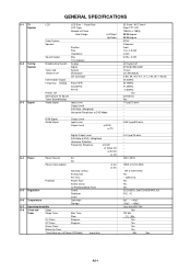
... G-3 Signal LCD Color System Speaker Sound Output Broadcasting System Tuner and Receive CH Intermediate Digital Frequency Analog Preset CH Stereo/Dual TV Sound Tuner Sound Muting Video Signal LCD Size / Visual Size LCD Type Number of Pixels View Range Position Size Impedance Max 10%(Typical) Analog Digital System Destination CH Coverage Picture(FP) Sound(FS) FP-FS Left/Right Up/Down Input Level Output Level S/N Ratio (Weighted) Horizontal Resolution at DVD Mode RGB Signal Audio Signal Output Level Input Level Output Level at DVD at TV Digital Output Level S/N Ratio at DVD (Weighted...
... G-3 Signal LCD Color System Speaker Sound Output Broadcasting System Tuner and Receive CH Intermediate Digital Frequency Analog Preset CH Stereo/Dual TV Sound Tuner Sound Muting Video Signal LCD Size / Visual Size LCD Type Number of Pixels View Range Position Size Impedance Max 10%(Typical) Analog Digital System Destination CH Coverage Picture(FP) Sound(FS) FP-FS Left/Right Up/Down Input Level Output Level S/N Ratio (Weighted) Horizontal Resolution at DVD Mode RGB Signal Audio Signal Output Level Input Level Output Level at DVD at TV Digital Output Level S/N Ratio at DVD (Weighted...

Service Manual
Page 5
... Yes Yes Yes Yes Yes Yes Yes Yes Yes Yes Yes Yes Yes Yes Yes Yes Yes Yes Yes No Yes Yes Yes Yes A2-2 VIEW MODE 1 2 3 4 5 6 7 8 9 0 ŋ ENT INPUT FLASH BACK VOL+ VOL- G-9 Remote Control GENERAL SPECIFICATIONS Unit Glow in Dark Remocon Remocon Format Format Custom Code Power Source Voltage(D.C) UM size x pcs Total Keys Keys POWER FUNCTION Source POWER DISPLAY LIGHT SEARCH+ SEARCH-
... Yes Yes Yes Yes Yes Yes Yes Yes Yes Yes Yes Yes Yes Yes Yes Yes Yes Yes Yes No Yes Yes Yes Yes A2-2 VIEW MODE 1 2 3 4 5 6 7 8 9 0 ŋ ENT INPUT FLASH BACK VOL+ VOL- G-9 Remote Control GENERAL SPECIFICATIONS Unit Glow in Dark Remocon Remocon Format Format Custom Code Power Source Voltage(D.C) UM size x pcs Total Keys Keys POWER FUNCTION Source POWER DISPLAY LIGHT SEARCH+ SEARCH-

Service Manual
Page 6
... Red, Green, Blue Auto Adjust Backlight Audio MTS Tone Control (Bass/Treble/Balance) Stable Sound Surround BBE SRS WOW (SRS 3D/Focus/Tru Bass) Variable Audio Out Tuning CH Program Air/Cable ADD/DELETE Label CH Label Video Label Favorite CH V-Chip Type RRT Setup Lock Hotel Lock Channel Lock Video Lock Panel Lock OSD Language Closed Caption CC Advanced View Mode (Picture Size) Picture Scroll Cinema Mode Aspect PFC(Power Factor circuit) Freeze frame PIP/POP Direct Input Selection Digital Out Dolby Digital MPEG...
... Red, Green, Blue Auto Adjust Backlight Audio MTS Tone Control (Bass/Treble/Balance) Stable Sound Surround BBE SRS WOW (SRS 3D/Focus/Tru Bass) Variable Audio Out Tuning CH Program Air/Cable ADD/DELETE Label CH Label Video Label Favorite CH V-Chip Type RRT Setup Lock Hotel Lock Channel Lock Video Lock Panel Lock OSD Language Closed Caption CC Advanced View Mode (Picture Size) Picture Scroll Cinema Mode Aspect PFC(Power Factor circuit) Freeze frame PIP/POP Direct Input Selection Digital Out Dolby Digital MPEG...
Service Manual
Page 7
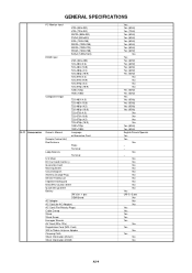
... 1920×1080i Owner's Manual Language w/Guarantee Card Remote Control Unit Rod Antenna Poles Terminal Loop Antenna Terminal U/V Mixer DC Car Cord (Center+) Guarantee Card Warning Sheet Circuit Diagram Antenna Change Plug Service Facility List Important Safeguard Dew/AHC Caution Sheet Quick Set-up Sheet Battery UM size x pcs OEM Brand AC Adapter AC Cord (for AC Adapter) AC Cord (Flat Polarity Plugs) Cable Cramp Stand Stand Screw Hexagon Wrench AV Cord (2Pin-1Pin) Registration...
... 1920×1080i Owner's Manual Language w/Guarantee Card Remote Control Unit Rod Antenna Poles Terminal Loop Antenna Terminal U/V Mixer DC Car Cord (Center+) Guarantee Card Warning Sheet Circuit Diagram Antenna Change Plug Service Facility List Important Safeguard Dew/AHC Caution Sheet Quick Set-up Sheet Battery UM size x pcs OEM Brand AC Adapter AC Cord (for AC Adapter) AC Cord (Flat Polarity Plugs) Cable Cramp Stand Stand Screw Hexagon Wrench AV Cord (2Pin-1Pin) Registration...

Service Manual
Page 8
... PC Monitor Input Analog Audio Digital Audio Output DC Jack (Center +) VHF/UHF Antenna Input Video Input 3 Audio Input 3 S - GENERAL SPECIFICATIONS G-12 Interface G-13 Set Size G-14 Weight G-15 Carton G-16 Material G-17 Environment Switch Indicator Terminals Top Power (Tact) Channel Up/Menu Up Channel Down/Menu Down Volume Up/Menu > Volume Down/Menu < Menu Play Eject Skip+, Search+ Skip-, Search- Input 1 Video Input 2 Audio Input 2 S - Still/Pause Stop Main Power SW Input Select Rear Main Power SW Power/Stand-By On Timer Side Video Input 1 Audio Input...
... PC Monitor Input Analog Audio Digital Audio Output DC Jack (Center +) VHF/UHF Antenna Input Video Input 3 Audio Input 3 S - GENERAL SPECIFICATIONS G-12 Interface G-13 Set Size G-14 Weight G-15 Carton G-16 Material G-17 Environment Switch Indicator Terminals Top Power (Tact) Channel Up/Menu Up Channel Down/Menu Down Volume Up/Menu > Volume Down/Menu < Menu Play Eject Skip+, Search+ Skip-, Search- Input 1 Video Input 2 Audio Input 2 S - Still/Pause Stop Main Power SW Input Select Rear Main Power SW Power/Stand-By On Timer Side Video Input 1 Audio Input...

Service Manual
Page 13
... and on the remote control for more than a the standard time in the appropriate condition. (See below chart.) Set Condition Power ON Set Key VOL. DOWN (Minimum) 6 Standard Time Operations 2 sec. SERVICE MODE LIST This unit is provided with the following SERVICE MODES so you set factory initialization, the memories are displayed on the screen. Can be checked of the INITIAL DATA of V-CHIP PASSWORD. 2 sec. 2 sec. DOWN...
... and on the remote control for more than a the standard time in the appropriate condition. (See below chart.) Set Condition Power ON Set Key VOL. DOWN (Minimum) 6 Standard Time Operations 2 sec. SERVICE MODE LIST This unit is provided with the following SERVICE MODES so you set factory initialization, the memories are displayed on the screen. Can be checked of the INITIAL DATA of V-CHIP PASSWORD. 2 sec. 2 sec. DOWN...

Service Manual
Page 14
... "update.dat" in CD to the topside of the USB connector cover, remove the USB connector cover. The Up-Date will appear on the set for the new DIGITAL SOFT FIRMWARE. Turn off the power. 7. Press both Channel button (1) on the remote control and the VOLUME DOWN button on the screen. 5. APJG176121 Parts Name 2007 USA DTV LCD ROM DISC Remarks Up-Date of WINDOWS2000 is used . Recommended USB Flash Memory...
... "update.dat" in CD to the topside of the USB connector cover, remove the USB connector cover. The Up-Date will appear on the set for the new DIGITAL SOFT FIRMWARE. Turn off the power. 7. Press both Channel button (1) on the remote control and the VOLUME DOWN button on the screen. 5. APJG176121 Parts Name 2007 USA DTV LCD ROM DISC Remarks Up-Date of WINDOWS2000 is used . Recommended USB Flash Memory...
Service Manual
Page 15
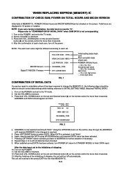
... you set and Channel button (6) on the screen. Set the VOLUME to minimum. 3. The unit will turn off (return to STANDBY MODE) to ADDRESS for further selection if necessary. 8. WHEN REPLACING EEPROM (MEMORY) IC CONFIRMATION OF CHECK SUM, POWER ON TOTAL HOURS AND MICON VERSION Initial total of MEMORY IC, POWER ON total hours and MICON VERSIONcan be checked on the remote control for...
... you set and Channel button (6) on the screen. Set the VOLUME to minimum. 3. The unit will turn off (return to STANDBY MODE) to ADDRESS for further selection if necessary. 8. WHEN REPLACING EEPROM (MEMORY) IC CONFIRMATION OF CHECK SUM, POWER ON TOTAL HOURS AND MICON VERSION Initial total of MEMORY IC, POWER ON total hours and MICON VERSIONcan be checked on the remote control for...

Service Manual
Page 16
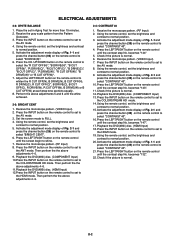
... On-Screen Display Adjustment 1. DOWN button on the remote control to normal position. 15. becomes "150" 5. Press the LEFT/RIGHT button on the remote control. Playback the DVD(480i) disc. (HDMI Input) 18. Press the INPUT button on the set to select "CONTRAST MAX". 16. FUNCTION 23 BAK LIGHT CENT 24 BAK LIGHT MAX 25 BAK LIGHT MIN 26 BRIGHT CENT 27 BRIGHT MAX 28 BRIGHT MIN 29 TINT 30 SHARP...
... On-Screen Display Adjustment 1. DOWN button on the remote control to normal position. 15. becomes "150" 5. Press the LEFT/RIGHT button on the remote control. Playback the DVD(480i) disc. (HDMI Input) 18. Press the INPUT button on the set to select "CONTRAST MAX". 16. FUNCTION 23 BAK LIGHT CENT 24 BAK LIGHT MAX 25 BAK LIGHT MIN 26 BRIGHT CENT 27 BRIGHT MAX 28 BRIGHT MIN 29 TINT 30 SHARP...
Service Manual
Page 17
... remote control to set to normal position. 5. Receive the monoscope pattern. (VIDEO Input) 2. Then perfrom the the above adjustments 5 and 6 until the screen begin to the AV mode. 8. Check if the picture is normal. Playback the DVD(480i) disc. (HDMI Input) 18. Using the remote control, set to normal position. 5. becomes "144" 5. D-2 Receive the gray scale pattern from the Pattern Generator. 3. Press the INPUT button on the remote control to select...
... remote control to set to normal position. 5. Receive the monoscope pattern. (VIDEO Input) 2. Then perfrom the the above adjustments 5 and 6 until the screen begin to the AV mode. 8. Check if the picture is normal. Playback the DVD(480i) disc. (HDMI Input) 18. Using the remote control, set to normal position. 5. becomes "144" 5. D-2 Receive the gray scale pattern from the Pattern Generator. 3. Press the INPUT button on the remote control to select...

Service Manual
Page 18
... remote control, set to the COLORSTREAM HD mode. 14. Playback the DVD(480i) disc. (COMPONENT Input) 13. Activate the adjustment mode display of Fig. 1-1 and press the channel button (33) on the remote control until the contrast step No. Check if the picture is normal. 6. becomes "113". 11. Using the remote control, set to the HDMI mode. 19. becomes "115" 5. Check if the picture is normal. 12. Press the INPUT button on the remote control to select...
... remote control, set to the COLORSTREAM HD mode. 14. Playback the DVD(480i) disc. (COMPONENT Input) 13. Activate the adjustment mode display of Fig. 1-1 and press the channel button (33) on the remote control until the contrast step No. Check if the picture is normal. 6. becomes "113". 11. Using the remote control, set to the HDMI mode. 19. becomes "115" 5. Check if the picture is normal. 12. Press the INPUT button on the remote control to select...

Service Manual
Page 21
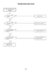
Yes No Is there voltage at pin 10 of IC402 6V? Yes Yes Is R412 broken? Check IC402 and peripheral circuit. Yes Change DIGITAL PCB. E-1 TROUBLESHOOTING GUIDE (LCD SECTION) POWER DOES NOT TUNER ON Is F401 broken? Check IC401 and peripheral circuit. No No Is there voltage at pin 1 No of IC401 19V? Change F401. Change R412.
Yes No Is there voltage at pin 10 of IC402 6V? Yes Yes Is R412 broken? Check IC402 and peripheral circuit. Yes Change DIGITAL PCB. E-1 TROUBLESHOOTING GUIDE (LCD SECTION) POWER DOES NOT TUNER ON Is F401 broken? Check IC401 and peripheral circuit. No No Is there voltage at pin 1 No of IC401 19V? Change F401. Change R412.
Service Manual
Page 25
Yes Is there color signal at No pins 33 and 35 of IC2401? Change DIGITAL PCB. No Is there color signal at Yes pins A9 and A13 of IC701? E-5 Adjust the color. Check Q701,Q702 and peripheral circuit. TROUBLESHOOTING GUIDE THE COLOR DOES NOT APPEAR Is setting of color No normal? Yes Is the color signal No received? Receive the color signal. Yes Check IC701 and peripheral circuit.
Yes Is there color signal at No pins 33 and 35 of IC2401? Change DIGITAL PCB. No Is there color signal at Yes pins A9 and A13 of IC701? E-5 Adjust the color. Check Q701,Q702 and peripheral circuit. TROUBLESHOOTING GUIDE THE COLOR DOES NOT APPEAR Is setting of color No normal? Yes Is the color signal No received? Receive the color signal. Yes Check IC701 and peripheral circuit.

Service Manual
Page 35
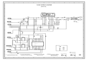
...26 25 HY27US08281A-TP FLASH MEMORY IC FOR FIRM UPDATE CP2401 YKF45-0036N 1 +5V 2 USBN 3 USBP 6 4 GND JG2412 JG2413 JG2414 R2422 15K R2423 15K FROM/TO AV SWITCH/JACK I2C_DATA I2C_CLK 5 FROM/TO MICON TX_[X242] RX_[X242] FROM/TO SOUND... G 4.7K D 5.0 I2C_CLK ATSC/CLEAR CABLE ASIC IC IC2401 X242 (14/14 USB/SERIAL) 0 AE22 USBPA 0 AD22 USBNA 0 AD23...SCHEMATIC DIAGRAM IS THE LATEST AT THE TIME NOTE:THE DC VOLTAGE AT EACH PART WAS MEASURED 1 OF PRINTING AND SUBJECT TO CHANGE WITHOUT NOTICE WITH THE DIGITAL TESTER WHEN THE COLOR BROADCAST WAS RECEIVED IN GOOD CONDITION AND PICTURE...
...26 25 HY27US08281A-TP FLASH MEMORY IC FOR FIRM UPDATE CP2401 YKF45-0036N 1 +5V 2 USBN 3 USBP 6 4 GND JG2412 JG2413 JG2414 R2422 15K R2423 15K FROM/TO AV SWITCH/JACK I2C_DATA I2C_CLK 5 FROM/TO MICON TX_[X242] RX_[X242] FROM/TO SOUND... G 4.7K D 5.0 I2C_CLK ATSC/CLEAR CABLE ASIC IC IC2401 X242 (14/14 USB/SERIAL) 0 AE22 USBPA 0 AD22 USBNA 0 AD23...SCHEMATIC DIAGRAM IS THE LATEST AT THE TIME NOTE:THE DC VOLTAGE AT EACH PART WAS MEASURED 1 OF PRINTING AND SUBJECT TO CHANGE WITHOUT NOTICE WITH THE DIGITAL TESTER WHEN THE COLOR BROADCAST WAS RECEIVED IN GOOD CONDITION AND PICTURE...

Service Manual
Page 41
... 3 STANDBY LED 4 POWER ON LED 5 3 D105 RB520S-30-TE61 R118 10K R117 10K 0 NC 5 NC 1 C107 16V10 V-S 2 2 GND IN OUT 0 5.0 5.0 2 C106 16V10 V-S 0 NC 4 NC 3 1 A H-17 NOTE: THIS SCHEMATIC DIAGRAM IS THE LATEST AT THE TIME OF PRINTING AND SUBJECT TO CHANGE WITHOUT NOTICE NOTE:THE DC VOLTAGE AT EACH PART WAS MEASURED WITH THE DIGITAL TESTER WHEN THE COLOR BROADCAST...
... 3 STANDBY LED 4 POWER ON LED 5 3 D105 RB520S-30-TE61 R118 10K R117 10K 0 NC 5 NC 1 C107 16V10 V-S 2 2 GND IN OUT 0 5.0 5.0 2 C106 16V10 V-S 0 NC 4 NC 3 1 A H-17 NOTE: THIS SCHEMATIC DIAGRAM IS THE LATEST AT THE TIME OF PRINTING AND SUBJECT TO CHANGE WITHOUT NOTICE NOTE:THE DC VOLTAGE AT EACH PART WAS MEASURED WITH THE DIGITAL TESTER WHEN THE COLOR BROADCAST...

Service Manual
Page 42
... 22 23 24 25 26 27 28 29 30 31 32 C931 16V100 V-S D702 UDZS12B NOTE: THIS SCHEMATIC DIAGRAM IS THE LATEST AT THE TIME OF PRINTING AND SUBJECT TO CHANGE WITHOUT NOTICE NOTE:THE DC VOLTAGE AT EACH PART WAS MEASURED WITH THE DIGITAL TESTER WHEN THE COLOR BROADCAST WAS RECEIVED IN GOOD CONDITION AND PICTURE IS NORMAL.
... 22 23 24 25 26 27 28 29 30 31 32 C931 16V100 V-S D702 UDZS12B NOTE: THIS SCHEMATIC DIAGRAM IS THE LATEST AT THE TIME OF PRINTING AND SUBJECT TO CHANGE WITHOUT NOTICE NOTE:THE DC VOLTAGE AT EACH PART WAS MEASURED WITH THE DIGITAL TESTER WHEN THE COLOR BROADCAST WAS RECEIVED IN GOOD CONDITION AND PICTURE IS NORMAL.
Service Manual
Page 43
... FRONT END DTUNER_AUDIO_SW FROM/TO FLASH 10 I2C_DATA I2C_CLK 11 1 NOTE: THIS SCHEMATIC DIAGRAM IS THE LATEST AT THE TIME OF PRINTING AND SUBJECT TO CHANGE WITHOUT NOTICE NOTE:THE DC VOLTAGE AT EACH PART WAS MEASURED WITH THE DIGITAL TESTER WHEN THE COLOR BROADCAST WAS RECEIVED IN GOOD CONDITION AND PICTURE IS NORMAL. A B C D E F SOUND SCHEMATIC DIAGRAM 8 (DIGITAL PCB) G H 8 7 FROM/TO POWER3 6 AT...
... FRONT END DTUNER_AUDIO_SW FROM/TO FLASH 10 I2C_DATA I2C_CLK 11 1 NOTE: THIS SCHEMATIC DIAGRAM IS THE LATEST AT THE TIME OF PRINTING AND SUBJECT TO CHANGE WITHOUT NOTICE NOTE:THE DC VOLTAGE AT EACH PART WAS MEASURED WITH THE DIGITAL TESTER WHEN THE COLOR BROADCAST WAS RECEIVED IN GOOD CONDITION AND PICTURE IS NORMAL. A B C D E F SOUND SCHEMATIC DIAGRAM 8 (DIGITAL PCB) G H 8 7 FROM/TO POWER3 6 AT...

Service Manual
Page 55
... HOLDER CORD --- 791WHA0125 PACKING SACK --- 791WHA0126 PACKING SACK --- 791WHA0130 LAMIFILM BAG --- 792WHA0716 PACKAGE STAND TOP --- 792WHA0717 PACKAGE STAND BOTTOM --- 792WHA0718 PACKAGE TOP --- 792WHA0719 PACKAGE BOTTOM --- 793WCD1810 GIFT BOX --- 89001122A2 SCREW --- 890CCOR001 CLEANING CLOTH PACK --- J31B0131A INSTRUCTION BOOK(E/F/S) --- NO. PART NO. DESCRIPTION 101 7A7010282A FRONT CABI ASS'Y 101A 701WPJ1487 CABINET FRONT 101B 702WNB0003 SHEET SPEAKER 101C 713WPA0415 GLASS LED 101D...
... HOLDER CORD --- 791WHA0125 PACKING SACK --- 791WHA0126 PACKING SACK --- 791WHA0130 LAMIFILM BAG --- 792WHA0716 PACKAGE STAND TOP --- 792WHA0717 PACKAGE STAND BOTTOM --- 792WHA0718 PACKAGE TOP --- 792WHA0719 PACKAGE BOTTOM --- 793WCD1810 GIFT BOX --- 89001122A2 SCREW --- 890CCOR001 CLEANING CLOTH PACK --- J31B0131A INSTRUCTION BOOK(E/F/S) --- NO. PART NO. DESCRIPTION 101 7A7010282A FRONT CABI ASS'Y 101A 701WPJ1487 CABINET FRONT 101B 702WNB0003 SHEET SPEAKER 101C 713WPA0415 GLASS LED 101D...


