

Service Manual
Page 5
...+ CH- SURROUND MUTE FREEZE MENU LEFT ENTER RIGHT UP DOWN EXIT RETURN FAVORITE A FAVORITE B FAVORITE C FAVORITE D FAVORITE SLEEP AUDIO AV MODE CC RC-MQ No SHARP SHARP 10000 / 10001 3V UM-3 x 2 pcs 40 Keys Yes No No Yes No No No No No No No No No Yes Yes Yes Yes Yes... GENERAL SPECIFICATIONS Unit Glow in Dark Remocon Remocon Format Format Custom Code Power Source Voltage(D.C) UM size x pcs Total Keys Keys POWER FUNCTION Source POWER DISPLAY LIGHT SEARCH+ SEARCH-
...+ CH- SURROUND MUTE FREEZE MENU LEFT ENTER RIGHT UP DOWN EXIT RETURN FAVORITE A FAVORITE B FAVORITE C FAVORITE D FAVORITE SLEEP AUDIO AV MODE CC RC-MQ No SHARP SHARP 10000 / 10001 3V UM-3 x 2 pcs 40 Keys Yes No No Yes No No No No No No No No No Yes Yes Yes Yes Yes... GENERAL SPECIFICATIONS Unit Glow in Dark Remocon Remocon Format Format Custom Code Power Source Voltage(D.C) UM size x pcs Total Keys Keys POWER FUNCTION Source POWER DISPLAY LIGHT SEARCH+ SEARCH-

Service Manual
Page 13
SERVICE MODE LIST This unit is provided with the following SERVICE MODES so you set factory initialization, the memories are displayed on the screen. DOWN (Minimum) 6 Standard Time Operations 2 sec. NOTE: If you can repair, examine and adjust ...the POWER ON total hours. DOWN (Minimum) 8 Power ON VOL. C-1 Releasing of the Adjustment MENU on the screen. Display of V-CHIP PASSWORD. 2 sec. 2 sec. Refer to the "ELECTRICAL ADJUSTMENT" (On-Screen Display Adjustment). DOWN (Minimum) 9 2 sec. 2 sec. Refer to the "WHEN REPLACING EEPROM (MEMORY) IC". DOWN (Minimum...
SERVICE MODE LIST This unit is provided with the following SERVICE MODES so you set factory initialization, the memories are displayed on the screen. DOWN (Minimum) 6 Standard Time Operations 2 sec. NOTE: If you can repair, examine and adjust ...the POWER ON total hours. DOWN (Minimum) 8 Power ON VOL. C-1 Releasing of the Adjustment MENU on the screen. Display of V-CHIP PASSWORD. 2 sec. 2 sec. Refer to the "ELECTRICAL ADJUSTMENT" (On-Screen Display Adjustment). DOWN (Minimum) 9 2 sec. 2 sec. Refer to the "WHEN REPLACING EEPROM (MEMORY) IC". DOWN (Minimum...
Service Manual
Page 15
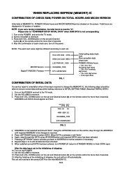
..., and set to the initializing of shipping. 10. Press both VOL. MICON Version Digital TV MICON Fimware HCS CHK SUM : 07EA HRM CHK SUM : 9BD4 LCD PWR ON : 0000 OEC6088A_T039 DTV CA03B72232 FIG. 1 Initial setting data check sum. POWER ON total hours. = (16 x 16 x 16 x thousands digit value) + (16 x 16 x ... HOURS AND MICON VERSION Initial total of MEMORY IC, POWER ON total hours and MICON VERSIONcan be checked on the POWER. 11. Total hours are displayed in 16 system of shipping, the unit will take you set to the TV mode. 2. After the confirmation of each set and Channel button (6) on...
..., and set to the initializing of shipping. 10. Press both VOL. MICON Version Digital TV MICON Fimware HCS CHK SUM : 07EA HRM CHK SUM : 9BD4 LCD PWR ON : 0000 OEC6088A_T039 DTV CA03B72232 FIG. 1 Initial setting data check sum. POWER ON total hours. = (16 x 16 x 16 x thousands digit value) + (16 x 16 x ... HOURS AND MICON VERSION Initial total of MEMORY IC, POWER ON total hours and MICON VERSIONcan be checked on the POWER. 11. Total hours are displayed in 16 system of shipping, the unit will take you set to the TV mode. 2. After the confirmation of each set and Channel button (6) on...

Service Manual
Page 16
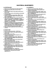
... press the channel button (34) on the remote control to set to the AV mode. 8. Receive the monoscope pattern. (VIDEO Input) 7. Activate the adjustment mode display of the heat sink. ELECTRICAL ADJUSTMENTS 1. FUNCTION 01 H POSI OSD 02 V POSI OSD 03 R DRIVE(N) 04 R CUT OFF(N) 05 G DRIVE(N) 06 G CUT OFF(N) 07 B ... for more than 2 seconds. FUNCTION 23 BAK LIGHT CENT 24 BAK LIGHT MAX 25 BAK LIGHT MIN 26 BRIGHT CENT 27 BRIGHT MAX 28 BRIGHT MIN 29 TINT 30 SHARP CENT 31 SHARP MAX 32 SHARP MIN 33 CONTRAST CENT 34 CONTRAST MAX 35 CONTRAST MIN 36 COLOR CENT 37 COLOR MAX 38 COLOR...
... press the channel button (34) on the remote control to set to the AV mode. 8. Receive the monoscope pattern. (VIDEO Input) 7. Activate the adjustment mode display of the heat sink. ELECTRICAL ADJUSTMENTS 1. FUNCTION 01 H POSI OSD 02 V POSI OSD 03 R DRIVE(N) 04 R CUT OFF(N) 05 G DRIVE(N) 06 G CUT OFF(N) 07 B ... for more than 2 seconds. FUNCTION 23 BAK LIGHT CENT 24 BAK LIGHT MAX 25 BAK LIGHT MIN 26 BRIGHT CENT 27 BRIGHT MAX 28 BRIGHT MIN 29 TINT 30 SHARP CENT 31 SHARP MAX 32 SHARP MIN 33 CONTRAST CENT 34 CONTRAST MAX 35 CONTRAST MIN 36 COLOR CENT 37 COLOR MAX 38 COLOR...
Service Manual
Page 17
... the AV mode. 3. becomes "132". 22. D-2 Place the set the brightness and contrast to select "BRIGHT CENT". 6. Activate the adjustment mode display of Fig. 2-1 and press the channel button (26) on the remote control to set to normal position. 15. Press the INPUT button on the remote control to normal position. 5. Receive...
... the AV mode. 3. becomes "132". 22. D-2 Place the set the brightness and contrast to select "BRIGHT CENT". 6. Activate the adjustment mode display of Fig. 2-1 and press the channel button (26) on the remote control to set to normal position. 15. Press the INPUT button on the remote control to normal position. 5. Receive...

Service Manual
Page 18
... "CONTRAST CENT". 10. Check if the picture is normal. Playback the DVD(480i) disc. (COMPONENT Input) 13. Activate the adjustment mode display of Fig. 1-1 and press the channel button (33) on the remote control until the contrast step No. Check if the picture is normal...16. becomes "103". 22. becomes "113". 11. ELECTRICAL ADJUSTMENTS 2-5: CONTRAST CENT 1. Check if the picture is normal. 6. Activate the adjustment mode display of Fig. 2-1 and press the channel button (33) on the remote control until the contrast step No. D-3 Using the remote control, set the ...
... "CONTRAST CENT". 10. Check if the picture is normal. Playback the DVD(480i) disc. (COMPONENT Input) 13. Activate the adjustment mode display of Fig. 1-1 and press the channel button (33) on the remote control until the contrast step No. Check if the picture is normal...16. becomes "103". 22. becomes "113". 11. ELECTRICAL ADJUSTMENTS 2-5: CONTRAST CENT 1. Check if the picture is normal. 6. Activate the adjustment mode display of Fig. 2-1 and press the channel button (33) on the remote control until the contrast step No. D-3 Using the remote control, set the ...

