
User Guide
Page 3
CONTENTS EN Contents 1 INTRODUCTION 3 2 SAFETY INFORMATION 5 3 INSTALLATION MATERIAL 8 3.1 Kit supplied with dishwasher 9 4 DIMENSIONS OF DISHWASHER 10 5 5.1 5.2 5.2.1 5.2.1.1 5.2.1.2 5.2.2 5.3 5.3.1 5.3.2 5.3.3 5.4 INSTALLATION AND HOOK-UP 11 Leveling...12 Connections 13 Connecting to the water supply 14 Connecting to the water tap 15 Connecting the drain hose 16 Electrical connections and warnings 22 Commissioning 23 Installation procedure 23 Procedure for mounting the door panel 25 Completion of installation 28 Testing ...31 1
CONTENTS EN Contents 1 INTRODUCTION 3 2 SAFETY INFORMATION 5 3 INSTALLATION MATERIAL 8 3.1 Kit supplied with dishwasher 9 4 DIMENSIONS OF DISHWASHER 10 5 5.1 5.2 5.2.1 5.2.1.1 5.2.1.2 5.2.2 5.3 5.3.1 5.3.2 5.3.3 5.4 INSTALLATION AND HOOK-UP 11 Leveling...12 Connections 13 Connecting to the water supply 14 Connecting to the water tap 15 Connecting the drain hose 16 Electrical connections and warnings 22 Commissioning 23 Installation procedure 23 Procedure for mounting the door panel 25 Completion of installation 28 Testing ...31 1

User Guide
Page 5
...;rst table in section 4). WARNINGS: a list of the appliance. The manual is added after the progressive number (e.g.: "Tab. 4-01a", Tab. 4-01b"). 3 If a table occupies more than one of our products. The tables are complete with detailed illustrations. INTRODUCTION EN 1 INTRODUCTION Thank you a step-by-step guide to installation of the appliance. INSTALLATION INSTRUCTIONS: for choosing one page, a letter...
...;rst table in section 4). WARNINGS: a list of the appliance. The manual is added after the progressive number (e.g.: "Tab. 4-01a", Tab. 4-01b"). 3 If a table occupies more than one of our products. The tables are complete with detailed illustrations. INTRODUCTION EN 1 INTRODUCTION Thank you a step-by-step guide to installation of the appliance. INSTALLATION INSTRUCTIONS: for choosing one page, a letter...

User Guide
Page 7
... THE DOOR. THE MANUFACTURER DECLINES ALL RESPONSIBILITY FOR USES OTHER THAN THOSE DESCRIBED ABOVE. INSTALLATION MUST BE PERFORMED IN COMPLIANCE WITH ALL THE DIRECTIVES IN FORCE IN THE COUNTRY OF INSTALLATION AND, IF THESE DO NOT EXIST: IN THE UNITED STATES THE NATIONAL ELECTRIC CODE; DISHWASHERS CERTIFIED FOR DOMESTIC USE ARE NOT SUITABLE FOR AUTHORISED FOOD FACTORIES. 5 INSTALLATION, REPAIRS AND SERVICING MUST...
... THE DOOR. THE MANUFACTURER DECLINES ALL RESPONSIBILITY FOR USES OTHER THAN THOSE DESCRIBED ABOVE. INSTALLATION MUST BE PERFORMED IN COMPLIANCE WITH ALL THE DIRECTIVES IN FORCE IN THE COUNTRY OF INSTALLATION AND, IF THESE DO NOT EXIST: IN THE UNITED STATES THE NATIONAL ELECTRIC CODE; DISHWASHERS CERTIFIED FOR DOMESTIC USE ARE NOT SUITABLE FOR AUTHORISED FOOD FACTORIES. 5 INSTALLATION, REPAIRS AND SERVICING MUST...
User Guide
Page 8
... INSTALLATION, DISCONNECT THE MAINS POWER SUPPLY FROM THE WORK AREA. WEAR SAFETY GLOVES. THE MANUFACTURER DECLINES ALL RESPONSIBILITY FOR DAMAGE TO PERSONS OR PROPERTY RESULTING FROM THE FAILURE TO GROUND THE APPLIANCE OR FROM A DEFECTIVE GROUND CONNECTION. IMMEDIATELY AFTER INSTALLATION, BRIEFLY TEST THE APPLIANCE FOLLOWING THE INSTRUCTIONS INDICATED BELOW. TWO PEOPLE WEARING SAFETY GLOVES ARE REQUIRED TO LIFT THE DISHWASHER...
... INSTALLATION, DISCONNECT THE MAINS POWER SUPPLY FROM THE WORK AREA. WEAR SAFETY GLOVES. THE MANUFACTURER DECLINES ALL RESPONSIBILITY FOR DAMAGE TO PERSONS OR PROPERTY RESULTING FROM THE FAILURE TO GROUND THE APPLIANCE OR FROM A DEFECTIVE GROUND CONNECTION. IMMEDIATELY AFTER INSTALLATION, BRIEFLY TEST THE APPLIANCE FOLLOWING THE INSTRUCTIONS INDICATED BELOW. TWO PEOPLE WEARING SAFETY GLOVES ARE REQUIRED TO LIFT THE DISHWASHER...

User Guide
Page 9
DO NOT USE EXTENSION CORDS, ADAPTORS OR SHUNT CONNECTIONS IN ORDER TO AVOID THE POSSIBILITY OF OVERHEATING OR BURNING, WITH CONSEQUENT FIRE HAZARD. WARNINGS EN NECT IT FROM THE ELECTRICAL POWER SUPPLY AND CALL THE NEAREST TECHNICAL SERVICE CENTRE. DO NOT ATTEMPT TO REPAIR THE APPLIANCE. IF IN DOUBT ABOUT THE CONTENTS OF THIS MANUAL, CONTACT THE TECHNICAL ASSISTANCE SERVICE. 7 THE...
DO NOT USE EXTENSION CORDS, ADAPTORS OR SHUNT CONNECTIONS IN ORDER TO AVOID THE POSSIBILITY OF OVERHEATING OR BURNING, WITH CONSEQUENT FIRE HAZARD. WARNINGS EN NECT IT FROM THE ELECTRICAL POWER SUPPLY AND CALL THE NEAREST TECHNICAL SERVICE CENTRE. DO NOT ATTEMPT TO REPAIR THE APPLIANCE. IF IN DOUBT ABOUT THE CONTENTS OF THIS MANUAL, CONTACT THE TECHNICAL ASSISTANCE SERVICE. 7 THE...

User Guide
Page 11
... the door (ref. H fig. 3-02); • 2 screw caps (ref. F fig. 3-02); • 4 screws for door panel (ref. C fig. 3-02); • 2 hooks for fixing the dishwasher to be fixed with screws (e.g.:+ marble or masonry), but it can be also used with the dishwasher comprises: • 1 adhesive steam guard (depending on the model) (ref. INSTALLATION INSTRUCTION EN 3.1 Kit supplied with dishwasher The kit supplied with...
... the door (ref. H fig. 3-02); • 2 screw caps (ref. F fig. 3-02); • 4 screws for door panel (ref. C fig. 3-02); • 2 hooks for fixing the dishwasher to be fixed with screws (e.g.:+ marble or masonry), but it can be also used with the dishwasher comprises: • 1 adhesive steam guard (depending on the model) (ref. INSTALLATION INSTRUCTION EN 3.1 Kit supplied with dishwasher The kit supplied with...

User Guide
Page 13
... WORK AREA. Only for free-standing models • It is installed next to a heat source, separate it with screws. Position the appliance in appliances under continuous worktops, securing them to mount a hob over a free-standing dishwasher. 11 To assure stability, only install built-in the chosen installation position. If the dishwasher is strictly forbidden to the adjacent kitchen units or worktop with a heat insulating panel...
... WORK AREA. Only for free-standing models • It is installed next to a heat source, separate it with screws. Position the appliance in appliances under continuous worktops, securing them to mount a hob over a free-standing dishwasher. 11 To assure stability, only install built-in the chosen installation position. If the dishwasher is strictly forbidden to the adjacent kitchen units or worktop with a heat insulating panel...
User Guide
Page 14
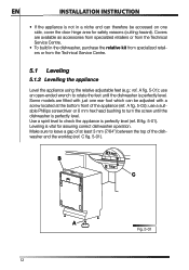
EN INSTALLATION INSTRUCTION • If the appliance is not in the dishwasher, purchase the relative kit from specialized retailers or from the Technical Service Centre. 5.1 Leveling 5.1.2 Levelling the appliance Level the appliance using the relative adjustable feet (e.g.: ref. Some models are available as accessories from specialized retailers or from the Technical Service Centre. • To build in a niche and can therefore be accessed...
EN INSTALLATION INSTRUCTION • If the appliance is not in the dishwasher, purchase the relative kit from specialized retailers or from the Technical Service Centre. 5.1 Leveling 5.1.2 Levelling the appliance Level the appliance using the relative adjustable feet (e.g.: ref. Some models are available as accessories from specialized retailers or from the Technical Service Centre. • To build in a niche and can therefore be accessed...
User Guide
Page 15
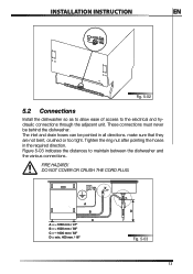
... the electrical and hydraulic connections through the adjacent unit. FIRE HAZARD! A B C A = 1200 mm / 47" B = 1500 mm / 59" C = 1600 mm / 63" D = min. 400 mm / 16" D Fig. 5-03 13 Tighten the ring nut after pointing the hoses in all directions. DO NOT COVER OR CRUSH THE CORD PLUG. The inlet and drain hoses can be behind the dishwasher. INSTALLATION INSTRUCTION EN Fig. 5-02 5.2 Connections Install the dishwasher...
... the electrical and hydraulic connections through the adjacent unit. FIRE HAZARD! A B C A = 1200 mm / 47" B = 1500 mm / 59" C = 1600 mm / 63" D = min. 400 mm / 16" D Fig. 5-03 13 Tighten the ring nut after pointing the hoses in all directions. DO NOT COVER OR CRUSH THE CORD PLUG. The inlet and drain hoses can be behind the dishwasher. INSTALLATION INSTRUCTION EN Fig. 5-02 5.2 Connections Install the dishwasher...

User Guide
Page 16
... power cord (ref. EN INSTALLATION INSTRUCTION A through hole for the hoses and power cord with a diameter of the through hole with a gasket. If the dishwasher is installed in a metal unit protect the edge of at least 8 cm (5/32") is required to the water supply PREVENTING THE RISK OF CLOGGING OR DAMAGE: IF THE WATER PIPE IS NEW OR HAS NOT BEEN USED FOR A LONG TIME, BEFORE CONNECTING...
... power cord (ref. EN INSTALLATION INSTRUCTION A through hole for the hoses and power cord with a diameter of the through hole with a gasket. If the dishwasher is installed in a metal unit protect the edge of at least 8 cm (5/32") is required to the water supply PREVENTING THE RISK OF CLOGGING OR DAMAGE: IF THE WATER PIPE IS NEW OR HAS NOT BEEN USED FOR A LONG TIME, BEFORE CONNECTING...

User Guide
Page 17
..., fitting the supplied filter (ref. INSTALLATION INSTRUCTION EN 5.2.1.1 Connecting to the water tap Connect the inlet hose to a sink spray may burst if installed on the same pipes feeding the dishwasher. If the appliance is fitted with hot water, washing times will be reduced by tightening another ¼ turn using the same methods described for connecting the appliance to the domestic hot water tap using a pair of less...
..., fitting the supplied filter (ref. INSTALLATION INSTRUCTION EN 5.2.1.1 Connecting to the water tap Connect the inlet hose to a sink spray may burst if installed on the same pipes feeding the dishwasher. If the appliance is fitted with hot water, washing times will be reduced by tightening another ¼ turn using the same methods described for connecting the appliance to the domestic hot water tap using a pair of less...

User Guide
Page 18
... the hose is not bent (ref. EN INSTALLATION INSTRUCTION Do not cut , the dishwasher will not work, water will leak and you may be injured. Fig. 5-06 When connecting the dishwasher drain hose to prevent cracks or breakages that the hose is cut the inlet hose (see fig. 5-06). The cable harness and electrical components must not come into contact with the hydraulic system and the water inlet and drain hoses.
... the hose is not bent (ref. EN INSTALLATION INSTRUCTION Do not cut , the dishwasher will not work, water will leak and you may be injured. Fig. 5-06 When connecting the dishwasher drain hose to prevent cracks or breakages that the hose is cut the inlet hose (see fig. 5-06). The cable harness and electrical components must not come into contact with the hydraulic system and the water inlet and drain hoses.

User Guide
Page 19
.... INSTALLATION INSTRUCTION EN 5.2.1.2 Connecting the drain hose Connecting to a drain Insert the relative hose into a drain with a piece of string. If horizontal extension hoses with a hole (ref. For this purpose, the hose support is fitted with a maximum length of 3m are used to fix it to the wall or the tap with a minimum diameter of 4 cm (1-37/64") (ref. B fig. 5-08) using the supplied hose support...
.... INSTALLATION INSTRUCTION EN 5.2.1.2 Connecting the drain hose Connecting to a drain Insert the relative hose into a drain with a piece of string. If horizontal extension hoses with a hole (ref. For this purpose, the hose support is fitted with a maximum length of 3m are used to fix it to the wall or the tap with a minimum diameter of 4 cm (1-37/64") (ref. B fig. 5-08) using the supplied hose support...
User Guide
Page 20
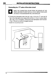
.... Connect the dishwasher drain hose (ref. if necessary, cut the corrugated section). * Available from any plumbing stockist B C D A Fig. 5-10 18 D fig. 5-10) (do not cut the end of the drain circuit MAKE THE CONNECTION UPLINE FROM THE SIPHON OF THE DRAIN LINE AND AT LEAST 400 mm (15-3/4") ABOVE THE FLOOR ON WHICH THE DISHWASHER WILL BE INSTALLED. 1. EN INSTALLATION INSTRUCTION Connecting to a "T" union of the dishwasher drain hose...
.... Connect the dishwasher drain hose (ref. if necessary, cut the corrugated section). * Available from any plumbing stockist B C D A Fig. 5-10 18 D fig. 5-10) (do not cut the end of the drain circuit MAKE THE CONNECTION UPLINE FROM THE SIPHON OF THE DRAIN LINE AND AT LEAST 400 mm (15-3/4") ABOVE THE FLOOR ON WHICH THE DISHWASHER WILL BE INSTALLED. 1. EN INSTALLATION INSTRUCTION Connecting to a "T" union of the dishwasher drain hose...

User Guide
Page 21
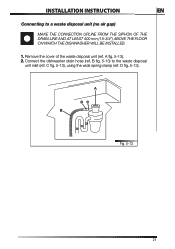
... THE SIPHON OF THE DRAIN LINE AND AT LEAST 400 mm (15-3/4") ABOVE THE FLOOR ON WHICH THE DISHWASHER WILL BE INSTALLED. 1. E fig. 5-12) (do not cut the end of the waste disposal unit (ref. if necessary, cut the corrugated section). C fig. 5-11) to the air gap (ref. INSTALLATION INSTRUCTION EN Connecting to 2") screw clamp*. 3. Remove the cover of the dishwasher drain hose (ref. H fig. 5-11...
... THE SIPHON OF THE DRAIN LINE AND AT LEAST 400 mm (15-3/4") ABOVE THE FLOOR ON WHICH THE DISHWASHER WILL BE INSTALLED. 1. E fig. 5-12) (do not cut the end of the waste disposal unit (ref. if necessary, cut the corrugated section). C fig. 5-11) to the air gap (ref. INSTALLATION INSTRUCTION EN Connecting to 2") screw clamp*. 3. Remove the cover of the dishwasher drain hose (ref. H fig. 5-11...

User Guide
Page 22
.... Connect the dishwasher drain hose (ref. A fig. 5-12) to the air gap (no waste disposal unit) MAKE THE CONNECTION UPLINE FROM THE SIPHON OF THE DRAIN LINE AND AT LEAST 400 mm (15-3/4") ABOVE THE FLOOR ON WHICH THE DISHWASHER WILL BE INSTALLED. 1. D fig. 5-12) (do not cut the end of the drain line, use a 38 to 50 mm (1-1/2 to the "T" union (ref. EN INSTALLATION INSTRUCTION Connecting to the air gap...
.... Connect the dishwasher drain hose (ref. A fig. 5-12) to the air gap (no waste disposal unit) MAKE THE CONNECTION UPLINE FROM THE SIPHON OF THE DRAIN LINE AND AT LEAST 400 mm (15-3/4") ABOVE THE FLOOR ON WHICH THE DISHWASHER WILL BE INSTALLED. 1. D fig. 5-12) (do not cut the end of the drain line, use a 38 to 50 mm (1-1/2 to the "T" union (ref. EN INSTALLATION INSTRUCTION Connecting to the air gap...
User Guide
Page 23
B fig. 5-13) to a waste disposal unit (no air gap) MAKE THE CONNECTION UPLINE FROM THE SIPHON OF THE DRAIN LINE AND AT LEAST 400 mm (15-3/4") ABOVE THE FLOOR ON WHICH THE DISHWASHER WILL BE INSTALLED. 1. A DC B Fig. 5-13 21 INSTALLATION INSTRUCTION EN Connecting to the waste disposal unit inlet (ref. Connect the dishwasher drain hose (ref. A fig. 5-13). 2. D fig. 5-13). Remove the cover of the waste disposal unit (ref. C fig. 5-13), using the wide spring clamp (ref.
B fig. 5-13) to a waste disposal unit (no air gap) MAKE THE CONNECTION UPLINE FROM THE SIPHON OF THE DRAIN LINE AND AT LEAST 400 mm (15-3/4") ABOVE THE FLOOR ON WHICH THE DISHWASHER WILL BE INSTALLED. 1. A DC B Fig. 5-13 21 INSTALLATION INSTRUCTION EN Connecting to the waste disposal unit inlet (ref. Connect the dishwasher drain hose (ref. A fig. 5-13). 2. D fig. 5-13). Remove the cover of the waste disposal unit (ref. C fig. 5-13), using the wide spring clamp (ref.

User Guide
Page 24
... WITH A SUPPLY CORD CONTAINING A GROUND WIRE AND PLUG. EN INSTALLATION INSTRUCTION 5.2.2 Electrical connections and warnings CHECK THAT THE VOLTAGE AND THE FREQUENCY OF THE MAINS MATCH THE RATINGS ON THE NAME PLATE OF THE APPLIANCE POSITIONED ON THE INNER EDGE OF THE DOOR. IN THE EVENT OF DAMAGE TO THE SUPPLY CORD, HAVE IT REPLACED BY THE MANUFACTURER OR AN AUTHORIZED TECHNICAL SERVICE CENTRE...
... WITH A SUPPLY CORD CONTAINING A GROUND WIRE AND PLUG. EN INSTALLATION INSTRUCTION 5.2.2 Electrical connections and warnings CHECK THAT THE VOLTAGE AND THE FREQUENCY OF THE MAINS MATCH THE RATINGS ON THE NAME PLATE OF THE APPLIANCE POSITIONED ON THE INNER EDGE OF THE DOOR. IN THE EVENT OF DAMAGE TO THE SUPPLY CORD, HAVE IT REPLACED BY THE MANUFACTURER OR AN AUTHORIZED TECHNICAL SERVICE CENTRE...

User Guide
Page 25
...;g. 5-16 if the steel guard is opened at the end of the dishwasher is applied). Never remove the plug by the manufacturer or an authorized service centre. see fig. 5-15 if the adhesive guard is damaged, have it replaced by pulling on the wire. The plug at the end of the same type and must be accessible after installation. INSTALLATION INSTRUCTION EN IF THE...
...;g. 5-16 if the steel guard is opened at the end of the dishwasher is applied). Never remove the plug by the manufacturer or an authorized service centre. see fig. 5-15 if the adhesive guard is damaged, have it replaced by pulling on the wire. The plug at the end of the same type and must be accessible after installation. INSTALLATION INSTRUCTION EN IF THE...

User Guide
Page 27
... door hooks with the 8 supplied screws (see fig. 5-18). mark the position of the panel, centering it along the upper side and matching up the reference locators (ref. A A Fig. 5-18 Use the screwdriver to make holes at the marked reference points. Fig. 5-19 25 Place the template on the panel. A fig. 5-18); INSTALLATION INSTRUCTION EN 5.3.2 Procedure for mounting the door panel Mount the door panel...
... door hooks with the 8 supplied screws (see fig. 5-18). mark the position of the panel, centering it along the upper side and matching up the reference locators (ref. A A Fig. 5-18 Use the screwdriver to make holes at the marked reference points. Fig. 5-19 25 Place the template on the panel. A fig. 5-18); INSTALLATION INSTRUCTION EN 5.3.2 Procedure for mounting the door panel Mount the door panel...

