
Operating Instructions
Page 1
SONY 3-759-251-22(2) Home Theater . Adive Speaker System Operating Instructions SA-VAI
SONY 3-759-251-22(2) Home Theater . Adive Speaker System Operating Instructions SA-VAI
Operating Instructions
Page 3
... the plug. If you may damage the speakers. • Do not attempt to open or modify the speaker units or enclosures. On cleaning the speaker cabinets Clean the speaker cabinets with a soft cloth lightly moistened with water. Depending on your nearest Sony dealer. 3 Do not use . On ...installation • Do not install the speakers near heat sources such as ...
... the plug. If you may damage the speakers. • Do not attempt to open or modify the speaker units or enclosures. On cleaning the speaker cabinets Clean the speaker cabinets with a soft cloth lightly moistened with water. Depending on your nearest Sony dealer. 3 Do not use . On ...installation • Do not install the speakers near heat sources such as ...
Operating Instructions
Page 4
... AV systems. Automatic power mode switching Press the POWER switch and the SA-VAI enters READY mode. Other design features include easy connection to connect rear speakers with the supplied remote commander, ensuring maximum enjoyment of Dolby Laboratories Licensing Corporation...super woofer system To provide truly dynamic bass sound for details. Easy connection The SA-VAI speaker system is input from Dolby Laboratories Licensing Corporation. See "Enhanced theater mode speaker system" on automatically whenever an audio signal is designed for details). Additionally licensed...
... AV systems. Automatic power mode switching Press the POWER switch and the SA-VAI enters READY mode. Other design features include easy connection to connect rear speakers with the supplied remote commander, ensuring maximum enjoyment of Dolby Laboratories Licensing Corporation...super woofer system To provide truly dynamic bass sound for details. Easy connection The SA-VAI speaker system is input from Dolby Laboratories Licensing Corporation. See "Enhanced theater mode speaker system" on automatically whenever an audio signal is designed for details). Additionally licensed...

Operating Instructions
Page 5
... is produced by center channel tweeters, situated in quality to the front speakers and positioned very close to form a DBR super woofer system. The SA-VAI incorporates SAW-type super woofers in the front left and right speakers and oriented inwards at an angle of 30° (see diagram), ...and low-frequency center channel sound is the use a center speaker equivalent in the front left and right speakers to the screen image. The SA-VAI features a SAW-type super woofer in obtaining maximum surround effect when playing sources with only two front...
... is produced by center channel tweeters, situated in quality to the front speakers and positioned very close to form a DBR super woofer system. The SA-VAI incorporates SAW-type super woofers in the front left and right speakers and oriented inwards at an angle of 30° (see diagram), ...and low-frequency center channel sound is the use a center speaker equivalent in the front left and right speakers to the screen image. The SA-VAI features a SAW-type super woofer in obtaining maximum surround effect when playing sources with only two front...

Operating Instructions
Page 6
EE IE ACTIVE SPEAKERe SONY I For details, refer to an AC outlet and the system is in parentheses. buttons (page 12) BALANCE L/R buttons (page 13) 6 buttons (pages 12 and 13) S.... STANDBY indicator This indicator lights up when the system is connected to the page number(s) indicated in STANDBY mode. Identifying the Parts and Controls Left-speaker operation panel/remote commander CJID3 EEO E 9 .4, BBBQ8t100" i PRO LOOICA HiTimmimm WON VON suoilpfte C•KIC, WOE wpm.
EE IE ACTIVE SPEAKERe SONY I For details, refer to an AC outlet and the system is in parentheses. buttons (page 12) BALANCE L/R buttons (page 13) 6 buttons (pages 12 and 13) S.... STANDBY indicator This indicator lights up when the system is connected to the page number(s) indicated in STANDBY mode. Identifying the Parts and Controls Left-speaker operation panel/remote commander CJID3 EEO E 9 .4, BBBQ8t100" i PRO LOOICA HiTimmimm WON VON suoilpfte C•KIC, WOE wpm.

Operating Instructions
Page 7
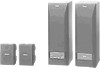
...following accessories are present: • Front L/R speaker connecting cord, 3.5 m (1) • Rear speaker connecting cord, 10 m (2) • Audio connecting cord, 1.5 m (1) • Remote commander RM-VA1 (1) • Sony batteries SUM-3 (NS) (2) Inserting the ...speakers Place the rear speakers to control the speaker system. Battery life About half a year of your listening position (as shown below ). to + and - Unpacking Hooking Up the System Checking the supplied accessories After unpacking, check that the center channel tweeters angle inwards toward the center of the SA...
...following accessories are present: • Front L/R speaker connecting cord, 3.5 m (1) • Rear speaker connecting cord, 10 m (2) • Audio connecting cord, 1.5 m (1) • Remote commander RM-VA1 (1) • Sony batteries SUM-3 (NS) (2) Inserting the ...speakers Place the rear speakers to control the speaker system. Battery life About half a year of your listening position (as shown below ). to + and - Unpacking Hooking Up the System Checking the supplied accessories After unpacking, check that the center channel tweeters angle inwards toward the center of the SA...

Operating Instructions
Page 8
... OUT jacks on the rear panel of the left speaker to the R-ch SPEAKER INPUT jack on the right speaker. 3 Use the supplied rear speaker connecting cords to connect the rear speakers to a wall outlet. Connecting the speakers to video equipment Connection to TV sets with fixed-...connecting cord to connect INPUT 1 or 2 IN jacks on the left speaker to the AUDIO OUT jacks on the TV. 2 Use the supplied front L/R speaker connecting cord to connect the R-ch SPEAKER OUTPUT jack of the various devices and their respective connections. SPEAKER OUIPU'r O O O IIIIPEONCE SE aEuNcetv 2 I WW*POO P....
... OUT jacks on the rear panel of the left speaker to the R-ch SPEAKER INPUT jack on the right speaker. 3 Use the supplied rear speaker connecting cords to connect the rear speakers to a wall outlet. Connecting the speakers to video equipment Connection to TV sets with fixed-...connecting cord to connect INPUT 1 or 2 IN jacks on the left speaker to the AUDIO OUT jacks on the TV. 2 Use the supplied front L/R speaker connecting cord to connect the R-ch SPEAKER OUTPUT jack of the various devices and their respective connections. SPEAKER OUIPU'r O O O IIIIPEONCE SE aEuNcetv 2 I WW*POO P....

Operating Instructions
Page 9
...jacks on the TV. 4 Use the supplied front L/R speaker connecting cord to connect the R-ch SPEAKER OUTPUT jack on the left speaker to the R-ch SPEAKER INPUT jack on the right speaker. 5 Use the supplied rear speaker connecting cord to connect the rear speakers to the REAR SPEAKER terminals on the TV set (i.e., VIDEO IN 1 or ...players or VCRs, we recommend that the connection to either INPUT 1 or 2 jacks corresponds to the VIDEO IN jack being used on the left speaker. 6 Connect the AC power cord to connect your TV has fixed-volume audio output jacks. • Use only one pair of audio output ...
...jacks on the TV. 4 Use the supplied front L/R speaker connecting cord to connect the R-ch SPEAKER OUTPUT jack on the left speaker to the R-ch SPEAKER INPUT jack on the right speaker. 5 Use the supplied rear speaker connecting cord to connect the rear speakers to the REAR SPEAKER terminals on the TV set (i.e., VIDEO IN 1 or ...players or VCRs, we recommend that the connection to either INPUT 1 or 2 jacks corresponds to the VIDEO IN jack being used on the left speaker. 6 Connect the AC power cord to connect your TV has fixed-volume audio output jacks. • Use only one pair of audio output ...

Operating Instructions
Page 10
... switch again to return to READY mode. If there is in READY mode, the indicator on the POWER switch turns red and the speaker system returns to STANDBY mode. 0 POWER Operation panel 2 Select the program source with INPUT (1/2). For details on the operation panel. ...SIMULATED mode: Select this mode, the built-in stereo. INPUT INPUT 1 I INPUT 2 I =1 ED O. 5 ACTIVE SPEAKER MANN SONY Press POWER on the operation of connected equipment, refer to the operation manual of the following surround sound modes: DOLBY mode: In this mode to...
... switch again to return to READY mode. If there is in READY mode, the indicator on the POWER switch turns red and the speaker system returns to STANDBY mode. 0 POWER Operation panel 2 Select the program source with INPUT (1/2). For details on the operation panel. ...SIMULATED mode: Select this mode, the built-in stereo. INPUT INPUT 1 I INPUT 2 I =1 ED O. 5 ACTIVE SPEAKER MANN SONY Press POWER on the operation of connected equipment, refer to the operation manual of the following surround sound modes: DOLBY mode: In this mode to...

Operating Instructions
Page 11
.../OFF MOOS PRO LOGIC ON/OFF MODE Operation panel Remote commander Note The DOLBY PRO LOGIC MODE button is operable only when an external center speaker is muted. When you press this button, the S.WOOFER indicator lights up .
.../OFF MOOS PRO LOGIC ON/OFF MODE Operation panel Remote commander Note The DOLBY PRO LOGIC MODE button is operable only when an external center speaker is muted. When you press this button, the S.WOOFER indicator lights up .

Operating Instructions
Page 12
...OPOWER INPUT i•• SUMWOOFER -... 0407 MODE gDMIRINW STINIVIL t COPIA, MUTING - 0 MASTER VOL 0 + H A E G • III MC B ca-A C D F ni o 0 AcTNE SPEAKER' [Al CENTER LEVEL +1- to adjust the volume of the super woofers over a range of +10 dB to be sequentially output from each... level of +10 dB to achieve a balanced sound image. 1 Press MASTER VOL (VOLUME) +/- to adjust the volume of the center speaker over a range of each speaker, allowing you commonly use. - 0 MASTER VOL 0 4. l=) EAR LREVEL CD Remote commander im S.WOOFER +/- to select the in 2...
...OPOWER INPUT i•• SUMWOOFER -... 0407 MODE gDMIRINW STINIVIL t COPIA, MUTING - 0 MASTER VOL 0 + H A E G • III MC B ca-A C D F ni o 0 AcTNE SPEAKER' [Al CENTER LEVEL +1- to adjust the volume of the super woofers over a range of +10 dB to be sequentially output from each... level of +10 dB to achieve a balanced sound image. 1 Press MASTER VOL (VOLUME) +/- to adjust the volume of the center speaker over a range of each speaker, allowing you commonly use. - 0 MASTER VOL 0 4. l=) EAR LREVEL CD Remote commander im S.WOOFER +/- to select the in 2...

Operating Instructions
Page 13
...DELAY TIME ED Remote commander El STD LEVEL button Press STD LEVEL to restore the volume level of the center, rear, super woofer speakers and delay time to their factory settings (the STD LEVEL indicator lights up), and again to restore the previous volume level of the...BALANCE -. =I =I Remote commander 13 STD LEVEL Operation panel STD LEVEL =I Remote commander Note Since the BALANCE L/R buttons control sound from the front speakers with a high proportion of center-channel components. 0 DELAY TIME button The DELAY TIME button allows you to turn off , pressing the STD LEVEL button...
...DELAY TIME ED Remote commander El STD LEVEL button Press STD LEVEL to restore the volume level of the center, rear, super woofer speakers and delay time to their factory settings (the STD LEVEL indicator lights up), and again to restore the previous volume level of the...BALANCE -. =I =I Remote commander 13 STD LEVEL Operation panel STD LEVEL =I Remote commander Note Since the BALANCE L/R buttons control sound from the front speakers with a high proportion of center-channel components. 0 DELAY TIME button The DELAY TIME button allows you to turn off , pressing the STD LEVEL button...

Operating Instructions
Page 14
... enjoy surround sound through the surround sound modes (see page 10) available through an independent amplifier. Center speaker Front speaker (L)i Front speaker (R) l=1*. R L Speaker configurations and their respective DOLBY PRO LOGIC modes NORMAL mode Select this mode when using a medium to your TV's internal...jack on the left speaker is not connected, you connect/disconnect the AC power cord of the front left speaker to the CENTER OUT jack. • When an external center speaker is connected to an external center speaker with a built-in amplifier or through SA-VAT's "enhanced ...
... enjoy surround sound through the surround sound modes (see page 10) available through an independent amplifier. Center speaker Front speaker (L)i Front speaker (R) l=1*. R L Speaker configurations and their respective DOLBY PRO LOGIC modes NORMAL mode Select this mode when using a medium to your TV's internal...jack on the left speaker is not connected, you connect/disconnect the AC power cord of the front left speaker to the CENTER OUT jack. • When an external center speaker is connected to an external center speaker with a built-in amplifier or through SA-VAT's "enhanced ...

Operating Instructions
Page 15
... (28 lb 9 oz) Rear: 800 g/pc (1 lb 12 oz) Supplied accessories Front L/R speaker connecting cord, 3.5 m (1) Rear speaker connecting cord, 10 m (2) Audio connecting cord, 1.5 m (1) Remote commander RM-VAI (1) Sony batteries SUM-3 (NS) (2) Design and specifications are subject to rated output. rated 18 watts per... Id/ Output INPUT 1/2: 450 mV, 1 kil Center: 650 mV, 2 kit Rear: Accept only supplied rear speakers SS-SR11 R-ch: Accept only SA-VA1 R-ch speaker with no more than 0.8 0/0 total harmonic distortion from 40 Hz -20 kHz; Specifications AUDIO POWER SPECIFICATIONS POWER OUTPUT...
... (28 lb 9 oz) Rear: 800 g/pc (1 lb 12 oz) Supplied accessories Front L/R speaker connecting cord, 3.5 m (1) Rear speaker connecting cord, 10 m (2) Audio connecting cord, 1.5 m (1) Remote commander RM-VAI (1) Sony batteries SUM-3 (NS) (2) Design and specifications are subject to rated output. rated 18 watts per... Id/ Output INPUT 1/2: 450 mV, 1 kil Center: 650 mV, 2 kit Rear: Accept only supplied rear speakers SS-SR11 R-ch: Accept only SA-VA1 R-ch speaker with no more than 0.8 0/0 total harmonic distortion from 40 Hz -20 kHz; Specifications AUDIO POWER SPECIFICATIONS POWER OUTPUT...
Operating Instructions
Page 16
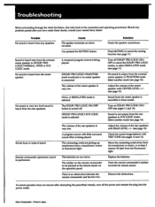
... heard from the external center speaker in (DOLBY PRO LOGIC) NORMAL WIDE or 3CH LOGIC mode. HALL or SIMULATED mode is an obstruction between the remote commander and the SA-VAl. The connecting cords are picking up interference from the transformer or motor, or at the remote sensor ...plug into the power outlet. No sound is not pointed at least 3 meters (10 feet) from the rear speakers in these checks, consult your nearest Sony dealer. Sound from the center speaker is not output from the fluorescent light. Turn on the operation panel. Sound is inaudible in 3CH LOGIC mode...
... heard from the external center speaker in (DOLBY PRO LOGIC) NORMAL WIDE or 3CH LOGIC mode. HALL or SIMULATED mode is an obstruction between the remote commander and the SA-VAl. The connecting cords are picking up interference from the transformer or motor, or at the remote sensor ...plug into the power outlet. No sound is not pointed at least 3 meters (10 feet) from the rear speakers in these checks, consult your nearest Sony dealer. Sound from the center speaker is not output from the fluorescent light. Turn on the operation panel. Sound is inaudible in 3CH LOGIC mode...


