
Parts List
Page 1
Illustrated Parts Manual Model Number: TBL-7800/R BACKPACK BLOWER P/N 40334 Rev 000 Date 6-19-07 Nikko Tanaka Engineering U.S.A.,Ltd.• 1028 4th Street SW, Bldg B • Auburn, WA 98001 • Phone: (253) 333-1200 • Fax: (253) 333-1212 www.tanakapowerequipment.com custsvc@nikko-tanaka-usa.com
Illustrated Parts Manual Model Number: TBL-7800/R BACKPACK BLOWER P/N 40334 Rev 000 Date 6-19-07 Nikko Tanaka Engineering U.S.A.,Ltd.• 1028 4th Street SW, Bldg B • Auburn, WA 98001 • Phone: (253) 333-1200 • Fax: (253) 333-1212 www.tanakapowerequipment.com custsvc@nikko-tanaka-usa.com

Parts List
Page 6
PARTS INFORMATION TBL-7800 CARBURETOR • FIGURE 3 0 ITEM PART NUMBER DESCRIPTION 3-0 4551600590 CARBURETOR SET 3-1 5752529290 BODY,PUMP 3-2 57825007200 SCREEN,INLET 3-8 4422515180 PUMP,PRIMING 3-9 4762515120 COVER,DIAPHRAGM 3-10 44725108200 BULB,PRIMING 3-11 5492516520 WASHER,THRUST 3-12 53925120200 SWIVEL 3-13 48925100200 RING,STOP 3-14 ~ ~ ~ GASKET,PUMP 3-15 ~ ~ ~ DIAPHRAGM,PUMP 3-16 ~ ~ ~ GASKET,DIAPHRAGM 3-17 ~ ~ ~ DIAPHRAGM,METERING 3-18 51425100200 SCREW,THROTTLE SET 3-19 54425164200 STAY,ADJUST,CABLE 3-20 99101060013 NUT,6 3-21 61425137200 ADJUSTER,...
PARTS INFORMATION TBL-7800 CARBURETOR • FIGURE 3 0 ITEM PART NUMBER DESCRIPTION 3-0 4551600590 CARBURETOR SET 3-1 5752529290 BODY,PUMP 3-2 57825007200 SCREEN,INLET 3-8 4422515180 PUMP,PRIMING 3-9 4762515120 COVER,DIAPHRAGM 3-10 44725108200 BULB,PRIMING 3-11 5492516520 WASHER,THRUST 3-12 53925120200 SWIVEL 3-13 48925100200 RING,STOP 3-14 ~ ~ ~ GASKET,PUMP 3-15 ~ ~ ~ DIAPHRAGM,PUMP 3-16 ~ ~ ~ GASKET,DIAPHRAGM 3-17 ~ ~ ~ DIAPHRAGM,METERING 3-18 51425100200 SCREW,THROTTLE SET 3-19 54425164200 STAY,ADJUST,CABLE 3-20 99101060013 NUT,6 3-21 61425137200 ADJUSTER,...

Parts List
Page 8
PARTS INFORMATION TBL-7800 FUEL TANK & FRAME • FIGURE 4 ITEM PART NUMBER DESCRIPTION 4-1 0103190580 FAN CASE,E 4-2 0113190580 FAN CASE S 4-3 8143190520 SCREW,I,5x25 4-4 2703190520 PIPE,ELBOW 4-5 99967095010 O-RING,G-95 4-6 1371600520 BOLT,FAN CASE,LONG 4-7 99178050010 NUT,LOCK 5 4-8 0543190580 COVER,INTAKE 4-9 8143190520 SCREW,I,5x25 4-10 1983190580 CLAMP,CORD 4-11 8153190520 SCREW,J,5x14 4-12 2833190520 TUBE 4-15 1273190580 FAN 4-16 8163190520 SCREW,K,6x35 4-17 7381600520 COVER,MUFFLER 4-18 8143190520 SCREW,I,5x25 4-21 0203190590...
PARTS INFORMATION TBL-7800 FUEL TANK & FRAME • FIGURE 4 ITEM PART NUMBER DESCRIPTION 4-1 0103190580 FAN CASE,E 4-2 0113190580 FAN CASE S 4-3 8143190520 SCREW,I,5x25 4-4 2703190520 PIPE,ELBOW 4-5 99967095010 O-RING,G-95 4-6 1371600520 BOLT,FAN CASE,LONG 4-7 99178050010 NUT,LOCK 5 4-8 0543190580 COVER,INTAKE 4-9 8143190520 SCREW,I,5x25 4-10 1983190580 CLAMP,CORD 4-11 8153190520 SCREW,J,5x14 4-12 2833190520 TUBE 4-15 1273190580 FAN 4-16 8163190520 SCREW,K,6x35 4-17 7381600520 COVER,MUFFLER 4-18 8143190520 SCREW,I,5x25 4-21 0203190590...

Parts List
Page 9
... A 5-10 0293190520 NUT,FLANGE,M6 5-11 99201080011 WASHER,8 5-12 1701600580 BUTTON,STOP 5-13 2661600520 COVER,STOP BUTTON 5-14 8853190580 WIRE,THROTTLE 5-15 1640703000 TUBE,7x300 5-16 2483190590 GRIP ASSY 5-17 4651600520 BOLT,WING 5-18 99161060012 NUT,WING,6 5-19 2403190520 WASHER 5-20 99153060013 NUT,CAP 5-22 8253190520 SCREW,M,5x16 www.tanakapowerequipment.com Page 8 QTY 1 1 1 1 1 1 1 1 1 1 2 1 1 1 1 1 1 1 2 1 2 COMMENTS custsvc@nikko-tanaka-usa.com PARTS INFORMATION TBL-7800 THROTTLE LEVER -
... A 5-10 0293190520 NUT,FLANGE,M6 5-11 99201080011 WASHER,8 5-12 1701600580 BUTTON,STOP 5-13 2661600520 COVER,STOP BUTTON 5-14 8853190580 WIRE,THROTTLE 5-15 1640703000 TUBE,7x300 5-16 2483190590 GRIP ASSY 5-17 4651600520 BOLT,WING 5-18 99161060012 NUT,WING,6 5-19 2403190520 WASHER 5-20 99153060013 NUT,CAP 5-22 8253190520 SCREW,M,5x16 www.tanakapowerequipment.com Page 8 QTY 1 1 1 1 1 1 1 1 1 1 2 1 1 1 1 1 1 1 2 1 2 COMMENTS custsvc@nikko-tanaka-usa.com PARTS INFORMATION TBL-7800 THROTTLE LEVER -

Parts List
Page 10
...6 ITEM PART NUMBER DESCRIPTION 6-1 8713190690 THROTTLE LEVER ASSY,R 6-2 2483190620 GRIP,R 6-3 2623190680 GRIP,L 6-4 8063190620 SCREW,A,4x14 6-5 2633190620 THROTTLE LEVER 6-6 2493190620 LEVER 6-7 3393190620 SHAFT,LEVER 6-8 2403190620 WASHER 6-9 8443190620 SPECIAL WASHER 6-10 2403190520 WASHER 6-11 99354006002 RING,STOP 6-12 1621600520 SWITCH,STOP 6-13 2621600520 SPRING,STOP SWITCH 6-14 8073190620 SCREW,B,4x10 6-15 1731600580 CORD 6-16 1741600580 CORD 6-17 8853190680 WIRE,THROTTLE 6-18 1640709400 TUBE,7x940 6-19 4653190620 BOLT,WING 6-20 99153060013 NUT,CAP...
...6 ITEM PART NUMBER DESCRIPTION 6-1 8713190690 THROTTLE LEVER ASSY,R 6-2 2483190620 GRIP,R 6-3 2623190680 GRIP,L 6-4 8063190620 SCREW,A,4x14 6-5 2633190620 THROTTLE LEVER 6-6 2493190620 LEVER 6-7 3393190620 SHAFT,LEVER 6-8 2403190620 WASHER 6-9 8443190620 SPECIAL WASHER 6-10 2403190520 WASHER 6-11 99354006002 RING,STOP 6-12 1621600520 SWITCH,STOP 6-13 2621600520 SPRING,STOP SWITCH 6-14 8073190620 SCREW,B,4x10 6-15 1731600580 CORD 6-16 1741600580 CORD 6-17 8853190680 WIRE,THROTTLE 6-18 1640709400 TUBE,7x940 6-19 4653190620 BOLT,WING 6-20 99153060013 NUT,CAP...
Owner's Manual
Page 2
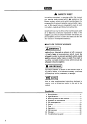
... the product to order new seals and affix the new seal(s) in the required location(s). ■ NOTES ON TYPES OF WARNINGS AWARNING Instructions labeled as shown at left , concern critical steps or procedures which must be followed in the use of the product. Contents 1. Symbols on the machine 6 4. Operation 28 9. Maintenance 32 10. Troubleshooting guide 42 2 Set up 20 7. Warning labels...
... the product to order new seals and affix the new seal(s) in the required location(s). ■ NOTES ON TYPES OF WARNINGS AWARNING Instructions labeled as shown at left , concern critical steps or procedures which must be followed in the use of the product. Contents 1. Symbols on the machine 6 4. Operation 28 9. Maintenance 32 10. Troubleshooting guide 42 2 Set up 20 7. Warning labels...
Owner's Manual
Page 4
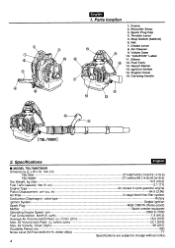
... 2000 to 7000 1.9 (64.3) 16.2 (572) 23.1 (816) 90 (201) 300 77 Specifications are subject to change without notice. Parts location 1. Throttle Lever 5. Specifications ■ MODEL TBL7800/7800R Dimensions (L x W x H) mm (in ) Air Filter Carburetor (Diaphragm) valve type Ignition System Spark Plug Muffler Operating Engine Speed rpm Fuel Consumption liter/h (fl. in ) TBL7800 TBL7800R Dry Weight kg (Ibs) Fuel Tank Capacity liter (fl. rg) 3 T 6 5 English 1. Ignition Switch 15. m/min (cfm) Max. Air Cleaner 9 9. m/min (cfm) Max. Recoil Starter 14. Choke Lever 8.
... 2000 to 7000 1.9 (64.3) 16.2 (572) 23.1 (816) 90 (201) 300 77 Specifications are subject to change without notice. Parts location 1. Throttle Lever 5. Specifications ■ MODEL TBL7800/7800R Dimensions (L x W x H) mm (in ) Air Filter Carburetor (Diaphragm) valve type Ignition System Spark Plug Muffler Operating Engine Speed rpm Fuel Consumption liter/h (fl. in ) TBL7800 TBL7800R Dry Weight kg (Ibs) Fuel Tank Capacity liter (fl. rg) 3 T 6 5 English 1. Ignition Switch 15. m/min (cfm) Max. Air Cleaner 9 9. m/min (cfm) Max. Recoil Starter 14. Choke Lever 8.
Owner's Manual
Page 6
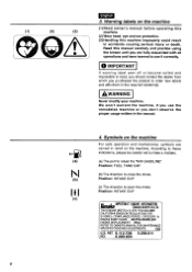
... machine, if you use it correctly. 0 IMPORTANT If warning label peel off or become soiled and impossible to open the choke Position: INTAKE CUP IMPORTANT ENGINE INFORMATION TANAKA KOGYO CO.,LTD. THIS ENGINE MEETS U.S. (1) 1 (2) (3) English 3. Symbols on the machine (1) Read owner's manual before operating this machine. (2) Wear head, eye and ear protection. (3) Handling this manual carefully and practice using the blower until you are...
... machine, if you use it correctly. 0 IMPORTANT If warning label peel off or become soiled and impossible to open the choke Position: INTAKE CUP IMPORTANT ENGINE INFORMATION TANAKA KOGYO CO.,LTD. THIS ENGINE MEETS U.S. (1) 1 (2) (3) English 3. Symbols on the machine (1) Read owner's manual before operating this machine. (2) Wear head, eye and ear protection. (3) Handling this manual carefully and practice using the blower until you are...

Owner's Manual
Page 12
... ft. (3 meters) away from the fueling point before operation, especially the muffler, air intakes and air filters. ■ WORKING PLAN • When planning your work schedule, allow plenty of time over which the product is securely tightened in the fuel line, the exhaust line, or the ignition wiring, do not use the blower until it has been repaired. 0 IMPORTANT Before starting operation, always make sure to rest...
... ft. (3 meters) away from the fueling point before operation, especially the muffler, air intakes and air filters. ■ WORKING PLAN • When planning your work schedule, allow plenty of time over which the product is securely tightened in the fuel line, the exhaust line, or the ignition wiring, do not use the blower until it has been repaired. 0 IMPORTANT Before starting operation, always make sure to rest...

Owner's Manual
Page 14
... become cracked or otherwise damaged. b) Use the full blower nozzle extension so the air stream can work close to replace without net in work area. e) Always check to be sure to the ground. Note that no debris has been blown onto someone else's property. Always disconnect the spark plug before installing or removing attachments. Check the work against the wind. a) Watch...
... become cracked or otherwise damaged. b) Use the full blower nozzle extension so the air stream can work close to replace without net in work area. e) Always check to be sure to the ground. Note that no debris has been blown onto someone else's property. Always disconnect the spark plug before installing or removing attachments. Check the work against the wind. a) Watch...
Owner's Manual
Page 16
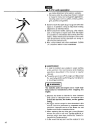
.... 6. Use special care around the fuel line, the muffler, and the ignition wiring. 4. All engine service except for loose fasteners and rusted or damaged parts. When replacing the any other equipment, CLEAN UP! Doing so may result in operation. After using power blowers instead of debris in trash receptacles. ■ MAINTENANCE t In order to touch the spark plug or plug cord while the engine is in being subjected to use only Tanaka products...
.... 6. Use special care around the fuel line, the muffler, and the ignition wiring. 4. All engine service except for loose fasteners and rusted or damaged parts. When replacing the any other equipment, CLEAN UP! Doing so may result in operation. After using power blowers instead of debris in trash receptacles. ■ MAINTENANCE t In order to touch the spark plug or plug cord while the engine is in being subjected to use only Tanaka products...

Owner's Manual
Page 22
... sparks near fuel. cooled 2-cycle engine use. (JASO FC GRADE OIL or ISO EGC GRADE) • Do not use BIA or TCW (2-stroke water-cooling type) mixed oil. • 11150/61 22 RECOMMENDED MIXING RATIO GASOLINE 50:OIL 1 (when using Tanaka two-cycle oil) 50:1 MIXING CHART GASOLINE gal. 1 234 5 2-CYCLE OIL fl.oz 2.6 5.2 7.8 10.4 13 GASOLINE liter 2-CYCLE OIL ml 1234 5 20 40 60 80 100 • Exhaust emission are controlled by oil...
... sparks near fuel. cooled 2-cycle engine use. (JASO FC GRADE OIL or ISO EGC GRADE) • Do not use BIA or TCW (2-stroke water-cooling type) mixed oil. • 11150/61 22 RECOMMENDED MIXING RATIO GASOLINE 50:OIL 1 (when using Tanaka two-cycle oil) 50:1 MIXING CHART GASOLINE gal. 1 234 5 2-CYCLE OIL fl.oz 2.6 5.2 7.8 10.4 13 GASOLINE liter 2-CYCLE OIL ml 1234 5 20 40 60 80 100 • Exhaust emission are controlled by oil...
Owner's Manual
Page 26
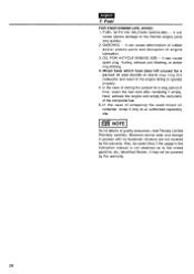
... the product for a period of the composite fuel. 6. Moreover,normal wear and change in the instruction manual is not observed as to the internal engine parts very quickly. 2. Also, be covered by the warranty. In the case of quality assurance, read Tanaka Limited Warranty carefully. EIFI NOTE As lot details of scrapping the used mixed oil container. It will cause severe damage to...
... the product for a period of the composite fuel. 6. Moreover,normal wear and change in the instruction manual is not observed as to the internal engine parts very quickly. 2. Also, be covered by the warranty. In the case of quality assurance, read Tanaka Limited Warranty carefully. EIFI NOTE As lot details of scrapping the used mixed oil container. It will cause severe damage to...

Owner's Manual
Page 28
... starter rope to the starter. • Do not let a person stand near the blower or the 28 This will reduce the cooling air and the engine could be damaged by overheating. 1. When the engine is cool, close the choke. (F7) NI (4) (2) F8 [TBL7800R] F9 [TBL78001 (1) '11"..44 (2) (3) (1) Choke Lever (2) Primer Bulb (3) OPEN (4) CLOSE 3. [TBL78001:1] Set the ignition switch to the start , hold the top of the control...
... starter rope to the starter. • Do not let a person stand near the blower or the 28 This will reduce the cooling air and the engine could be damaged by overheating. 1. When the engine is cool, close the choke. (F7) NI (4) (2) F8 [TBL7800R] F9 [TBL78001 (1) '11"..44 (2) (3) (1) Choke Lever (2) Primer Bulb (3) OPEN (4) CLOSE 3. [TBL78001:1] Set the ignition switch to the start , hold the top of the control...
Owner's Manual
Page 30
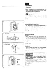
... to adjust the idle speed, use the adjustment screw on the top side of carburetor. (1) Idling Adjustment Screw • STOPPING ENGINE [TBL7800] • Move the throttle lever to overchoking, open the choke and repeat pulling the rope. ■ ADJUSTING IDLE SPEED (F11) • The idling speed is pushed the plug won't give off sparks until the engine stops. (F12) (1) Stop Switch [TBL7800R] • Move the throttle lever to the idling position and set for a minute to the stop position, close the choke lever...
... to adjust the idle speed, use the adjustment screw on the top side of carburetor. (1) Idling Adjustment Screw • STOPPING ENGINE [TBL7800] • Move the throttle lever to overchoking, open the choke and repeat pulling the rope. ■ ADJUSTING IDLE SPEED (F11) • The idling speed is pushed the plug won't give off sparks until the engine stops. (F12) (1) Stop Switch [TBL7800R] • Move the throttle lever to the idling position and set for a minute to the stop position, close the choke lever...

Owner's Manual
Page 32
... object. Contact with rotating blower fan or hot muffler may increase fuel consumption while cutting down the engine power. • Never clean a paper filter by any service to the blower. The filter may be damaged and resultant dust contamination can diminish engine performance. 32 System/Compornent Air Filter Fuel Leaks Fuel Filter Fuel Line Spark Plug Muffler Muffler Spark Arrester Cooling System Screws/Nuts/Bolts Cylinder Exhaust Port English 9. Maintenance Maintenance, replacement, or repair of the emission control device and systems may...
... object. Contact with rotating blower fan or hot muffler may increase fuel consumption while cutting down the engine power. • Never clean a paper filter by any service to the blower. The filter may be damaged and resultant dust contamination can diminish engine performance. 32 System/Compornent Air Filter Fuel Leaks Fuel Filter Fuel Line Spark Plug Muffler Muffler Spark Arrester Cooling System Screws/Nuts/Bolts Cylinder Exhaust Port English 9. Maintenance Maintenance, replacement, or repair of the emission control device and systems may...

Owner's Manual
Page 34
... gasoline. (1) Screen (2) Element (3) Holder (4) Retainer • SPARK PLUG • The spark plug may cause poor acceleration of the fueling port using a small wire hook. REPLACEMENT PLUG IS A NGK CMR7H OR CHAMPION RZ7C. F15 (1) Vo0 . (2) English 9. Unscrew 2 knob bolts and remove the air cleaner cover. AWARNING Saturate the air filter in fresh, non flammable cleaning solution (ex. The spark gap should be taken out of the engine. Squeeze the air filter to distribute the oil completely...
... gasoline. (1) Screen (2) Element (3) Holder (4) Retainer • SPARK PLUG • The spark plug may cause poor acceleration of the fueling port using a small wire hook. REPLACEMENT PLUG IS A NGK CMR7H OR CHAMPION RZ7C. F15 (1) Vo0 . (2) English 9. Unscrew 2 knob bolts and remove the air cleaner cover. AWARNING Saturate the air filter in fresh, non flammable cleaning solution (ex. The spark gap should be taken out of the engine. Squeeze the air filter to distribute the oil completely...

Owner's Manual
Page 36
... and clean as necessary with a wire brush. In the State of exhaust leakage is loose, the muffler may get loose during operation which may result in engine catching on fire. F18 r O F19 (1) 0 ( ) 36 English 9. Remove the muffler, insert a screwdriver into the vent, and wipe away any sign of California it is required by three bolts to equip a spark arrester when a gas powered tool...
... and clean as necessary with a wire brush. In the State of exhaust leakage is loose, the muffler may get loose during operation which may result in engine catching on fire. F18 r O F19 (1) 0 ( ) 36 English 9. Remove the muffler, insert a screwdriver into the vent, and wipe away any sign of California it is required by three bolts to equip a spark arrester when a gas powered tool...

Owner's Manual
Page 38
.... Maintenance (1) Three Bolts (2) Spark Arrester I AIR INLET NET 0 IMPORTANT • Blowing air is free from the air inlet net. Before each use , thus causing the product to remove any damage. • IGNITION COIL AIR GAP INSPECTION • If the gap is attached in the engine becoming overheated and damaged. (1) Net AWARNING Never use the blower without the net of the blower. When air flow has dropped down during use , check that...
.... Maintenance (1) Three Bolts (2) Spark Arrester I AIR INLET NET 0 IMPORTANT • Blowing air is free from the air inlet net. Before each use , thus causing the product to remove any damage. • IGNITION COIL AIR GAP INSPECTION • If the gap is attached in the engine becoming overheated and damaged. (1) Net AWARNING Never use the blower without the net of the blower. When air flow has dropped down during use , check that...

Owner's Manual
Page 40
.... Drain a fuel tank and push the primer bulb until it becomes empty of fuel. 2 .Remove the spark plug and drop a spoonful of children. 40 Maintenance AWARNING The flap on screws or bolts used to the unit. 0 IMPORTANT Do not apply liquid type screw lock glue on the end of glue may fall from the operator, which could result in a dry, dust free place, out of the reach of 2- cycle oil...
.... Drain a fuel tank and push the primer bulb until it becomes empty of fuel. 2 .Remove the spark plug and drop a spoonful of children. 40 Maintenance AWARNING The flap on screws or bolts used to the unit. 0 IMPORTANT Do not apply liquid type screw lock glue on the end of glue may fall from the operator, which could result in a dry, dust free place, out of the reach of 2- cycle oil...


