
User Manual
Page 3
... used batteries according to moisture. SAFETY INSTRUCTIONS Always read the safety instructions carefully. The openings on card or module. Always unplug the power cord before connecting the equipment to force open the battery. All cautions and warnings on the equipment should be damaged. The equipment has not worked well or you cannot get the equipment checked by a service personnel: The power cord or plug...
... used batteries according to moisture. SAFETY INSTRUCTIONS Always read the safety instructions carefully. The openings on card or module. Always unplug the power cord before connecting the equipment to force open the battery. All cautions and warnings on the equipment should be damaged. The equipment has not worked well or you cannot get the equipment checked by a service personnel: The power cord or plug...

User Manual
Page 4
... Panel Ports ...12 RJ-45 Port...12 USB Ports...12 Line-Out...12 Mic/Line-In ...12 Connectors...13 SATA Ports ...13 VGA Connector: VGA 13 Power Button Connector: PW_BN 14 USB Pin Connector: USB 2/3 14 KB/MS Connector 15 SPI (Serial Peripheral Interface): JSPI 15 LED Connector: JLED 16 LPC Connector: JLPC 17 System Management Bus: SMBus 17 Jumpers ...18 Clear CMOS ...18 AT/ATX Power ...18 Rear Audio Select: JAudio 19 CCChhhaaapppttteeerrr333 Daughter Cards 20 NSD7200-A Card Layout 20 Power Cable Connection 21 NSD7200-B Card Layout...
... Panel Ports ...12 RJ-45 Port...12 USB Ports...12 Line-Out...12 Mic/Line-In ...12 Connectors...13 SATA Ports ...13 VGA Connector: VGA 13 Power Button Connector: PW_BN 14 USB Pin Connector: USB 2/3 14 KB/MS Connector 15 SPI (Serial Peripheral Interface): JSPI 15 LED Connector: JLED 16 LPC Connector: JLPC 17 System Management Bus: SMBus 17 Jumpers ...18 Clear CMOS ...18 AT/ATX Power ...18 Rear Audio Select: JAudio 19 CCChhhaaapppttteeerrr333 Daughter Cards 20 NSD7200-A Card Layout 20 Power Cable Connection 21 NSD7200-B Card Layout...

User Manual
Page 5
Power Button Cable Connection 23 USB Cable Connection 23 LED and Reset Cable Connection 24 CCChhhaaapppttteeerrr444 BIOS Setup...26 Entering the BIOS Setup Menu 27 Control Keys ...28 Navigating the BIOS Menus 29 Getting Help...30 Main Menu...31 Standard CMOS Features 31 Advanced BIOS Features 31 Advanced Chipset Features 31 Integrated Peripherals 31 Power Management Setup 31 PnP/PCI Configurations 31 PC Health Status 32 Frequency/Voltage Control 32 Load Optimized Defaults 32 Set Supervisor Password 32 Set User Password 32 Save & Exit Setup 32 Exit...
Power Button Cable Connection 23 USB Cable Connection 23 LED and Reset Cable Connection 24 CCChhhaaapppttteeerrr444 BIOS Setup...26 Entering the BIOS Setup Menu 27 Control Keys ...28 Navigating the BIOS Menus 29 Getting Help...30 Main Menu...31 Standard CMOS Features 31 Advanced BIOS Features 31 Advanced Chipset Features 31 Integrated Peripherals 31 Power Management Setup 31 PnP/PCI Configurations 31 PC Health Status 32 Frequency/Voltage Control 32 Load Optimized Defaults 32 Set Supervisor Password 32 Set User Password 32 Save & Exit Setup 32 Exit...

User Manual
Page 6
... 45 PCI Delay Transaction 45 VIA PWR Management 45 Integrated Peripherals 46 OnChip IDE Channel 1 46 IDE HDD Block Mode 46 SATA Controller ...46 Azalia HDA Controller 46 Onboard LAN Boot ROM 46 VIA Wireless LAN Support 46 Super IO Device ...47 Internal Serial Port 1 47 VIA OnChip IDE Device 48 IDE Prefetch Mode 48 CF Card UDMA66 48 IDE DMA Transfer Access 48 Compact Flash PIO 48 Compact Flash UDMA 48 USB Device Setting 49 USB 1.0 Controller 49 USB 2.0 Controller 49 USB Operation Mode 49 USB Keyboard...
... 45 PCI Delay Transaction 45 VIA PWR Management 45 Integrated Peripherals 46 OnChip IDE Channel 1 46 IDE HDD Block Mode 46 SATA Controller ...46 Azalia HDA Controller 46 Onboard LAN Boot ROM 46 VIA Wireless LAN Support 46 Super IO Device ...47 Internal Serial Port 1 47 VIA OnChip IDE Device 48 IDE Prefetch Mode 48 CF Card UDMA66 48 IDE DMA Transfer Access 48 Compact Flash PIO 48 Compact Flash UDMA 48 USB Device Setting 49 USB 1.0 Controller 49 USB 2.0 Controller 49 USB Operation Mode 49 USB Keyboard...

User Manual
Page 19
... 2 GND 3 DC_12V 4 DC_12V Note: Before inserting the power supply connector, always make sure the power plug is inserted in the proper orientation and the pins are installed correctly to connect the external cable battery. This 2-pin connector used to ensure that all components are aligned. N701 User's Manual Power Connectors The VIA EPIA-N701 mainboard supports a 4-pin ATX power connector for the system power input. Pin Signal 1 1 A3V (+3.0V) 2 GND 11 External CMOS Battery Connector: BAT1 The mainboard comes with external CMOS battery connector.
... 2 GND 3 DC_12V 4 DC_12V Note: Before inserting the power supply connector, always make sure the power plug is inserted in the proper orientation and the pins are installed correctly to connect the external cable battery. This 2-pin connector used to ensure that all components are aligned. N701 User's Manual Power Connectors The VIA EPIA-N701 mainboard supports a 4-pin ATX power connector for the system power input. Pin Signal 1 1 A3V (+3.0V) 2 GND 11 External CMOS Battery Connector: BAT1 The mainboard comes with external CMOS battery connector.

User Manual
Page 20
Line-Out Use for connecting to external speakers or headphones. This port allows the connection to USB2.0 devices. These ports are provided on the back panel. Mic/Line-In Use for connecting to a microphone or Line-in signal. 12 USB Ports Two standard USB 2.0 ports are used to connect to a Local Area Network (LAN) through a network hub. N701 User's Manual Back Panel Ports The back panel has the following ports: RJ-45 Port The board provides a standard RJ-45 (Gigabit Ethernet).
Line-Out Use for connecting to external speakers or headphones. This port allows the connection to USB2.0 devices. These ports are provided on the back panel. Mic/Line-In Use for connecting to a microphone or Line-in signal. 12 USB Ports Two standard USB 2.0 ports are used to connect to a Local Area Network (LAN) through a network hub. N701 User's Manual Back Panel Ports The back panel has the following ports: RJ-45 Port The board provides a standard RJ-45 (Gigabit Ethernet).

User Manual
Page 21
The current SATA interface allows up to a VGA output cable. Pin Signal 1 GND 3 CRT_R 5 CRT_G 7 CRT_B 9 GND 11 GND 13 GND Pin Signal 2 +5V 4 SPD2 6 SPCLK2 8 CRT_H2 10 CRT_VS 12 GND 14 Key 1 13 13 Port 2 Port 1 VGA Connector: VGA 2 This pin header connects to 300MB/s data transfer rate, faster than the standard parallel ATA with 133 MB/s (UltraDMA). N701 User's Manual Connectors SATA Ports These next generation connectors support the thin SATA cables for primary internal storage devices.
The current SATA interface allows up to a VGA output cable. Pin Signal 1 GND 3 CRT_R 5 CRT_G 7 CRT_B 9 GND 11 GND 13 GND Pin Signal 2 +5V 4 SPD2 6 SPCLK2 8 CRT_H2 10 CRT_VS 12 GND 14 Key 1 13 13 Port 2 Port 1 VGA Connector: VGA 2 This pin header connects to 300MB/s data transfer rate, faster than the standard parallel ATA with 133 MB/s (UltraDMA). N701 User's Manual Connectors SATA Ports These next generation connectors support the thin SATA cables for primary internal storage devices.

User Manual
Page 38
N701 User's Manual Getting Help The BIOS setup program provides a "General Help" screen. Press to exit the help screen displays the keys for using and navigating the BIOS setup. You can display this screen from any menu/sub-menu by pressing . The help screen. 30
N701 User's Manual Getting Help The BIOS setup program provides a "General Help" screen. Press to exit the help screen displays the keys for using and navigating the BIOS setup. You can display this screen from any menu/sub-menu by pressing . The help screen. 30

User Manual
Page 39
... and PCI configurations. 31 PnP/PCI Configurations Use this menu to set chipset specific features and optimize system performance. Standard CMOS Features Use this menu to set onboard power management functions. Power Management Setup Use this menu to set basic system configurations. Use arrow keys to select the items and press to set onboard peripherals features. N701 User's Manual Main Menu The Main Menu contains twelve setup functions and two exit choices. Integrated Peripherals Use this menu to accept or enter Sub-menu.
... and PCI configurations. 31 PnP/PCI Configurations Use this menu to set chipset specific features and optimize system performance. Standard CMOS Features Use this menu to set onboard power management functions. Power Management Setup Use this menu to set basic system configurations. Use arrow keys to select the items and press to set onboard peripherals features. N701 User's Manual Main Menu The Main Menu contains twelve setup functions and two exit choices. Integrated Peripherals Use this menu to accept or enter Sub-menu.

User Manual
Page 47
... boots, or only when you are running OS/2 operating system with greater than 64MB of RAM on the system. Settings: [Non-OS2, OS2] HDD S.M.A.R.T Capability Settings: [Disabled, Enabled] Video BIOS Shadow Enabled copies Video BIOS to run BIOS Setup MPS Version Control for OS Settings: [1.1, 1.4] OS Select for DRAM > 64MB Select OS2 only if you enter Setup. Settings Description Setup Password prompt appears only when end users try to repeat the signal from a depressed key. N701 User's Manual...
... boots, or only when you are running OS/2 operating system with greater than 64MB of RAM on the system. Settings: [Non-OS2, OS2] HDD S.M.A.R.T Capability Settings: [Disabled, Enabled] Video BIOS Shadow Enabled copies Video BIOS to run BIOS Setup MPS Version Control for OS Settings: [1.1, 1.4] OS Select for DRAM > 64MB Select OS2 only if you enter Setup. Settings Description Setup Password prompt appears only when end users try to repeat the signal from a depressed key. N701 User's Manual...

User Manual
Page 58
N701 User's Manual USB Mouse Function Settings: [Disabled, Enabled] USB Storage Function Enable or disable Legacy support of USB Mass Storage. Settings: [Disabled, Enabled] 50
N701 User's Manual USB Mouse Function Settings: [Disabled, Enabled] USB Storage Function Enable or disable Legacy support of USB Mass Storage. Settings: [Disabled, Enabled] 50

User Manual
Page 60
... override this option. Settings Always On Suspend -> Off Description Screen is always on even when system enters power saving mode Screen is pressed for more than four seconds. N701 User's Manual Suspend Mode Sets the length of time for older VGA drivers. Settings Delay 4 Sec Instant-Off Description System is turned off if power button is turned off when system enters power saving mode Video Off Method Settings: [Blank Screen, V/H SYNC+Blank, DPMS Support] Soft...
... override this option. Settings Always On Suspend -> Off Description Screen is always on even when system enters power saving mode Screen is pressed for more than four seconds. N701 User's Manual Suspend Mode Sets the length of time for older VGA drivers. Settings Delay 4 Sec Instant-Off Description System is turned off if power button is turned off when system enters power saving mode Video Off Method Settings: [Blank Screen, V/H SYNC+Blank, DPMS Support] Soft...

User Manual
Page 64
... an experienced user. PNP OS Installed Settings No Yes Description BIOS will initialize all the PnP cards BIOS will be initialized by the PnP operating system Reset Configuration Data Settings Disabled Enabled Description Default setting Resets the ESCD (Extended System Configuration Data) after exiting BIOS Setup if a newly installed PCI card or the system configuration prevents the operating system from loading 56 The rest of the cards will only initialize the PnP cards used for booting (VGA, IDE...
... an experienced user. PNP OS Installed Settings No Yes Description BIOS will initialize all the PnP cards BIOS will be initialized by the PnP operating system Reset Configuration Data Settings Disabled Enabled Description Default setting Resets the ESCD (Extended System Configuration Data) after exiting BIOS Setup if a newly installed PCI card or the system configuration prevents the operating system from loading 56 The rest of the cards will only initialize the PnP cards used for booting (VGA, IDE...

User Manual
Page 71
... changed . A message will need to be reentered to be changed . To cancel the process press . See "Security Option" in length) and press . A supervisor password and a user password. When a supervisor password is booted. To set the password, type the password (up to request the password each time the system is used , the BIOS Setup program can set. Additionally, when a password is enabled, the BIOS can be set password from CMOS memory. The new password will show up to enter a new password...
... changed . A message will need to be reentered to be changed . To cancel the process press . See "Security Option" in length) and press . A supervisor password and a user password. When a supervisor password is booted. To set the password, type the password (up to request the password each time the system is used , the BIOS Setup program can set. Additionally, when a password is enabled, the BIOS can be set password from CMOS memory. The new password will show up to enter a new password...

User Manual
Page 77
... audio chip. VIA USB 2.0 Driver: Enhances VIA USB 2.0 ports. VIA Graphics Driver: Enhances the onboard VIA graphic chip. N701 User's Manual CD Content VIA 4in1 Drivers: Contains VIA ATAPI Vendor Support Driver (enables the performance enhancing bus mastering functions on ATAcapable Hard Disk Drives and ensures IDE device compatibility), AGP VxD Driver (provides service routines to your VGA driver and interface directly to hardware, providing fast graphical access), IRQ Routing Miniport Driver (sets the system's PCI IRQ routing sequence) and VIA INF Driver (enables the VIA Power Management...
... audio chip. VIA USB 2.0 Driver: Enhances VIA USB 2.0 ports. VIA Graphics Driver: Enhances the onboard VIA graphic chip. N701 User's Manual CD Content VIA 4in1 Drivers: Contains VIA ATAPI Vendor Support Driver (enables the performance enhancing bus mastering functions on ATAcapable Hard Disk Drives and ensures IDE device compatibility), AGP VxD Driver (provides service routines to your VGA driver and interface directly to hardware, providing fast graphical access), IRQ Routing Miniport Driver (sets the system's PCI IRQ routing sequence) and VIA INF Driver (enables the VIA Power Management...

Operation Guide
Page 5
... SODIMM slot - AT/ATX power mode - SPI 4/8 Mbit flash memory Windows 2000/XP/Vista, Linux - System power management and temperature monitoring - non-condensing) - January 7, 2009 - 3 - Up to change without prior notice. Fan speed detection - CPU voltage monitoring - Award BIOS - Integrated VIA Chrome9™ HC3 DX9 3D/2D Graphics and unified video decoding acceleration - 1 x VIA VT6130 PCIe Gigabit LAN controller - Clear CMOS - Wake-on-LAN, Keyboard power-on, RTC Timer power-on pin header - 1 x +12V power input connector - 1 x MIC-in/Line-in switch header...
... SODIMM slot - AT/ATX power mode - SPI 4/8 Mbit flash memory Windows 2000/XP/Vista, Linux - System power management and temperature monitoring - non-condensing) - January 7, 2009 - 3 - Up to change without prior notice. Fan speed detection - CPU voltage monitoring - Award BIOS - Integrated VIA Chrome9™ HC3 DX9 3D/2D Graphics and unified video decoding acceleration - 1 x VIA VT6130 PCIe Gigabit LAN controller - Clear CMOS - Wake-on-LAN, Keyboard power-on, RTC Timer power-on pin header - 1 x +12V power input connector - 1 x MIC-in/Line-in switch header...

Operation Guide
Page 8
... for latest updates on a monthly basis • Installing a third party driver (such as the ALSA driver from the VEPD website at http://a2000.viatech.com. N701 Operating Guide VIA N701 Microsoft and Linux Driver Support MICROSOFT DRIVER SUPPORT The VIA N701 is highly compatible with Microsoft operating systems. The latest Windows 2000 and Windows XP drivers can be downloaded from the Advanced Linux Sound Architecture project for integrated audio) For...
... for latest updates on a monthly basis • Installing a third party driver (such as the ALSA driver from the VEPD website at http://a2000.viatech.com. N701 Operating Guide VIA N701 Microsoft and Linux Driver Support MICROSOFT DRIVER SUPPORT The VIA N701 is highly compatible with Microsoft operating systems. The latest Windows 2000 and Windows XP drivers can be downloaded from the Advanced Linux Sound Architecture project for integrated audio) For...
Setup Guide
Page 1
... software! .... ....... 1. AirriGO Hello! The front panel has a power button and USB port. Processor VIA C7-D 1.5GHz NanoBGA2 Processor / 400MHz FSB Chipset VIA VX800 Advanced All-in-one system processor System Memory DDR2 667 Memory up to 2GB (SODIMM) LAN VIA VT6130 PCI Express Gigabit Ethernet Controller Audio I/O VIA VT1708B High Definition Audio Codec 2 x SATA II 3.5-inch HDD Expansion Bay Bootable built-in CF socket Audio ports (Line-Out and Mic/Line-In) RJ-45 GigaLAN port 3 x USB 2.0 ports VGA port...
... software! .... ....... 1. AirriGO Hello! The front panel has a power button and USB port. Processor VIA C7-D 1.5GHz NanoBGA2 Processor / 400MHz FSB Chipset VIA VX800 Advanced All-in-one system processor System Memory DDR2 667 Memory up to 2GB (SODIMM) LAN VIA VT6130 PCI Express Gigabit Ethernet Controller Audio I/O VIA VT1708B High Definition Audio Codec 2 x SATA II 3.5-inch HDD Expansion Bay Bootable built-in CF socket Audio ports (Line-Out and Mic/Line-In) RJ-45 GigaLAN port 3 x USB 2.0 ports VGA port...

Setup Guide
Page 2
... what BIOS version and software version you are using, and provides you need to make it convenient for a lower tolerance. - AriTiGO A2000 Barebone Storage PC System Navigation\-buttons iGO A2000 System Management Tool Main Menu Schedule Preference About ,d) CPU Fan Speed: System Temperature: HOD Status : bd 2588 RPM 52 t Schedule Frererence About window -...., The content in a future update of the System Management Tool. like this easy to use control to start...
... what BIOS version and software version you are using, and provides you need to make it convenient for a lower tolerance. - AriTiGO A2000 Barebone Storage PC System Navigation\-buttons iGO A2000 System Management Tool Main Menu Schedule Preference About ,d) CPU Fan Speed: System Temperature: HOD Status : bd 2588 RPM 52 t Schedule Frererence About window -...., The content in a future update of the System Management Tool. like this easy to use control to start...

Installation Guide
Page 1
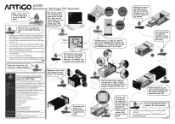
... hole. 4) Setting: Check the BIOS setting and ensure the USB port is enabled. 5) Driver: Software driver is available at VIA support website at the side is secondary and only for VIA VT6656 WLAN controller. The software you need is for dual antenna purposes. Install the driver and your corresponding operating system, the WiFi module driver is under Support > Drivers section. The white end connects to the motherboard USB pin header. Next, connect both black ground wires to the center gold header...
... hole. 4) Setting: Check the BIOS setting and ensure the USB port is enabled. 5) Driver: Software driver is available at VIA support website at the side is secondary and only for VIA VT6656 WLAN controller. The software you need is for dual antenna purposes. Install the driver and your corresponding operating system, the WiFi module driver is under Support > Drivers section. The white end connects to the motherboard USB pin header. Next, connect both black ground wires to the center gold header...
