Specifications
Page 1
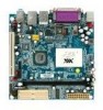
... BIOS flash 1 x SMBus connector 1 x LVDS/DVI/TTL module connector, for 18/24-bit dual channel LVDS panel (an add-on card is required) 1 x CD audio-in connector 1 x CIR connector (switchable for KB/MS) 1 x Front panel audio connector for Line-out and Mic-in 1 x Front panel connector 2 x Fan connectors for CPU and system fans 1 x ATX power connector 1 x PS2 mouse port 1 x PS2 keyboard port 1 x Parallel port 1 x VGA port 1 x Serial port 2 x RJ-45 LAN ports 4 x USB 2.0 ports 3 x Audio jacks: Line-out, Line-in and Mic-in (vertical, Smart 5.1 support) Award BIOS LPC 4/8Mbit flash memory Windows...
... BIOS flash 1 x SMBus connector 1 x LVDS/DVI/TTL module connector, for 18/24-bit dual channel LVDS panel (an add-on card is required) 1 x CD audio-in connector 1 x CIR connector (switchable for KB/MS) 1 x Front panel audio connector for Line-out and Mic-in 1 x Front panel connector 2 x Fan connectors for CPU and system fans 1 x ATX power connector 1 x PS2 mouse port 1 x PS2 keyboard port 1 x Parallel port 1 x VGA port 1 x Serial port 2 x RJ-45 LAN ports 4 x USB 2.0 ports 3 x Audio jacks: Line-out, Line-in and Mic-in (vertical, Smart 5.1 support) Award BIOS LPC 4/8Mbit flash memory Windows...

Specifications
Page 2
... Packing List Items 1 x ATA-66/100/133 IDE ribbon cable 1 x General installation guide 1 x Driver Utility CD 1 x I /O PS/2 mouse Parallel port Accessories RJ-45 Line-out Line-in PS/2 keyboard VGA-out COM USB Mic-in WLAN USB Module 802.11 b/g standards PWB-M120 DC-DC power board: 12-24V input/120W output DVI-03 Supports DVI monitor LVDS-07 Supports 18/24 bit LCD panel display EXT-PCI 1 to change without notice. Update...
... Packing List Items 1 x ATA-66/100/133 IDE ribbon cable 1 x General installation guide 1 x Driver Utility CD 1 x I /O PS/2 mouse Parallel port Accessories RJ-45 Line-out Line-in PS/2 keyboard VGA-out COM USB Mic-in WLAN USB Module 802.11 b/g standards PWB-M120 DC-DC power board: 12-24V input/120W output DVI-03 Supports DVI monitor LVDS-07 Supports 18/24 bit LCD panel display EXT-PCI 1 to change without notice. Update...
User Manual
Page 4
... THIS EQUIPMENT IN AN ENVIRONMENT UNCONDITIONED, STORAGE TEMPERATURE ABOVE 60 C (140F), IT MAY DAMAGE THE EQUIPMENT. Place the power cord in such a way that people cannot step on the equipment should be noted. 10. Always read the safety instructions carefully. 2. Caution: Only use the appropriate battery specified for this User's Manual for air convection hence protects the equipment...
... THIS EQUIPMENT IN AN ENVIRONMENT UNCONDITIONED, STORAGE TEMPERATURE ABOVE 60 C (140F), IT MAY DAMAGE THE EQUIPMENT. Place the power cord in such a way that people cannot step on the equipment should be noted. 10. Always read the safety instructions carefully. 2. Caution: Only use the appropriate battery specified for this User's Manual for air convection hence protects the equipment...

User Manual
Page 6
... Mainboard Specifications 2 Mainboard Layout 4 Back Panel Layout 5 Back Panel Ports 6 Slots 6 Onboard Connectors 7 Onboard Jumpers 7 Chapter 2 8 Installation 8 CPU 9 Memory Module Installation 11 Connecting the Power Supply 12 Back Panel Ports 13 Connectors 16 Jumpers 24 Slots 26 Chapter 3 27 BIOS Setup 27 Entering Setup 28 Control Keys 29 Navigating the BIOS Menus 30 Getting Help 31 Main Menu 32 Standard CMOS Features 34 IDE Drives 35 Advanced BIOS Features 36 Hard Disk Boot Priority 39 Advanced Chipset Features 40 AGP & P2P Bridge Control 42 CPU & PCI Bus Control...
... Mainboard Specifications 2 Mainboard Layout 4 Back Panel Layout 5 Back Panel Ports 6 Slots 6 Onboard Connectors 7 Onboard Jumpers 7 Chapter 2 8 Installation 8 CPU 9 Memory Module Installation 11 Connecting the Power Supply 12 Back Panel Ports 13 Connectors 16 Jumpers 24 Slots 26 Chapter 3 27 BIOS Setup 27 Entering Setup 28 Control Keys 29 Navigating the BIOS Menus 30 Getting Help 31 Main Menu 32 Standard CMOS Features 34 IDE Drives 35 Advanced BIOS Features 36 Hard Disk Boot Priority 39 Advanced Chipset Features 40 AGP & P2P Bridge Control 42 CPU & PCI Bus Control...

User Manual
Page 10
Chapter 1 MAINBOARD SPECIFICATIONS CPU • VIA Luke CoreFusion™ Processor Chipset • VIA VT8237R-series South Bridge Graphics • Integrated UniChrome™ Pro AGP with MPEG-2 Acceleration Audio • VIA VT1618 AC'97 Codec with 6-channel support Memory • 1 x DDR 400 DIMM slot (up to 1 GB) Expansion Slot • 1 x PCI slot IDE • 2 x UltraDMA 133/100 connectors LAN • • VIA VT6103L 10/100 Ethernet PHY VIA VT6107 10/100 Fast Ethernet (default) or VT6122 Gigabit Ethernet Controller 2
Chapter 1 MAINBOARD SPECIFICATIONS CPU • VIA Luke CoreFusion™ Processor Chipset • VIA VT8237R-series South Bridge Graphics • Integrated UniChrome™ Pro AGP with MPEG-2 Acceleration Audio • VIA VT1618 AC'97 Codec with 6-channel support Memory • 1 x DDR 400 DIMM slot (up to 1 GB) Expansion Slot • 1 x PCI slot IDE • 2 x UltraDMA 133/100 connectors LAN • • VIA VT6103L 10/100 Ethernet PHY VIA VT6107 10/100 Fast Ethernet (default) or VT6122 Gigabit Ethernet Controller 2

User Manual
Page 11
...; 2 x Serial ATA connectors • 1 x SM Bus pin header • 1 x KBMS pin header (KB/MS or CIR) • 1 x Digital I/O pin header • 2 x Fan connectors (CPU Fan and System Fan) • 1 x LVDS/TTL/DVI (an add-on card is required) • 1 x Front-Panel pin header • 1 x WP pin header • 1 x LVDS_DVI pin header for 24-bit/Dual 12-bit LVDS interface selection • 1 x Buzzer BIOS • • Award BIOS with 2/4/8Mbit flash memory capacity ACPI1.0b, SMBIOS2.3 and DMI2.1 Form Factor • Mini-ITX...
...; 2 x Serial ATA connectors • 1 x SM Bus pin header • 1 x KBMS pin header (KB/MS or CIR) • 1 x Digital I/O pin header • 2 x Fan connectors (CPU Fan and System Fan) • 1 x LVDS/TTL/DVI (an add-on card is required) • 1 x Front-Panel pin header • 1 x WP pin header • 1 x LVDS_DVI pin header for 24-bit/Dual 12-bit LVDS interface selection • 1 x Buzzer BIOS • • Award BIOS with 2/4/8Mbit flash memory capacity ACPI1.0b, SMBIOS2.3 and DMI2.1 Form Factor • Mini-ITX...

User Manual
Page 15
.../TTL/DVI SATA 1-2 CD-In SMBus SYSFAN USB 3-6 Description Power cable connector COM port 2/3/4 pin headers CPU fan connector Fast Infrared Radiation connector Digital I/O connector Front Audio connector Front panel connector IDE drive connectors Keyboard and Mouse connector LVDS/TTL/DVI connector Serial ATA 1 and 2 connectors CD-In connector SMBus connector System fan connector Universal Serial Bus 2.0 connectors 3-6 ONBOARD JUMPERS Jumper CLEAR_CMOS J1-J3 WP LVDS_DVI Description Reset CMOS settings COM2-COM4 voltage selector BIOS write protection setting 24-bit/Dual 12-bit LVDS interface...
.../TTL/DVI SATA 1-2 CD-In SMBus SYSFAN USB 3-6 Description Power cable connector COM port 2/3/4 pin headers CPU fan connector Fast Infrared Radiation connector Digital I/O connector Front Audio connector Front panel connector IDE drive connectors Keyboard and Mouse connector LVDS/TTL/DVI connector Serial ATA 1 and 2 connectors CD-In connector SMBus connector System fan connector Universal Serial Bus 2.0 connectors 3-6 ONBOARD JUMPERS Jumper CLEAR_CMOS J1-J3 WP LVDS_DVI Description Reset CMOS settings COM2-COM4 voltage selector BIOS write protection setting 24-bit/Dual 12-bit LVDS interface...

User Manual
Page 23
Installation Note: The audio ports can enable the function by clicking the "Vinyl Audio" icon on the back panel. Audio Port The Line-Out jack is for connecting to Smart 5.1 6-channel audio output. Jack Line-out Line-in Microphone 2-channel Line-out Line-in Microphone 6-channel Front (Left/Right) Rear (Left/Right) Center/Sub-woofer 15 You can be switched to external speakers or headphones. Shown below...
Installation Note: The audio ports can enable the function by clicking the "Vinyl Audio" icon on the back panel. Audio Port The Line-Out jack is for connecting to Smart 5.1 6-channel audio output. Jack Line-out Line-in Microphone 2-channel Line-out Line-in Microphone 6-channel Front (Left/Right) Rear (Left/Right) Center/Sub-woofer 15 You can be switched to external speakers or headphones. Shown below...

User Manual
Page 32
... boot failure. Keep Setting Keep CMOS setting Clear CMOS setting 1 2 3 OFF ON ON ON ON OFF 123 Clear 123 Caution: Except when clearing the RTC RAM, never remove the cap on the board. The following settings apply to pins 2 and 3 afterwards. To reset the CMOS settings, set the jumper on pins 1 and 2 while the system is reserved for setting some mainboard functions. J1-J3 enable you to change the settings of the mainboard functions using the jumpers. Clear CMOS Connector: CLEAR_CMOS The onboard CMOS RAM...
... boot failure. Keep Setting Keep CMOS setting Clear CMOS setting 1 2 3 OFF ON ON ON ON OFF 123 Clear 123 Caution: Except when clearing the RTC RAM, never remove the cap on the board. The following settings apply to pins 2 and 3 afterwards. To reset the CMOS settings, set the jumper on pins 1 and 2 while the system is reserved for setting some mainboard functions. J1-J3 enable you to change the settings of the mainboard functions using the jumpers. Clear CMOS Connector: CLEAR_CMOS The onboard CMOS RAM...

User Manual
Page 43
... Defaults The specifications of your hard disk vendor or system manufacturer. Select "Auto" whenever possible. Settings: [None, Auto, Manual] Settings: [CHS, LBA, Large, Auto] Formatted size of the storage device Number of cylinders Number of heads Write precompensation Cylinder location of the landing zone Number of the menu. Below is from your drive must match with the drive table. IDE DRIVES BIOS Setup Phoenix - AwardBIOS CMOS Setup Utility IDE Channel 0 Master IDE HDD Auto-Detection [Press Enter] Item Help IDE Channel 0 Master Access Mode...
... Defaults The specifications of your hard disk vendor or system manufacturer. Select "Auto" whenever possible. Settings: [None, Auto, Manual] Settings: [CHS, LBA, Large, Auto] Formatted size of the storage device Number of cylinders Number of heads Write precompensation Cylinder location of the landing zone Number of the menu. Below is from your drive must match with the drive table. IDE DRIVES BIOS Setup Phoenix - AwardBIOS CMOS Setup Utility IDE Channel 0 Master IDE HDD Auto-Detection [Press Enter] Item Help IDE Channel 0 Master Access Mode...
User Manual
Page 45
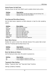
Setting Enabled Disabled Description Enable alternate boot device No alternate boot device allowed Boot Up NumLock Status Set the NumLock status when the system is powered on. Setting LS120 Hard Disk CDROM ZIP100 USB-FDD USB-ZIP USB-CDROM Legacy LAN Disabled Description Boot from LS-120 drive Boot from the HDD Boot from CD-ROM Boot from ATAPI ZIP drive Boot from USB floppy drive Boot from USB ZIP drive Boot from USB CDROM Boot from network drive Disable the boot device sequence Boot Other Device Enables the system to boot from the "First/Second/Third Boot Device" list. BIOS Setup ...
Setting Enabled Disabled Description Enable alternate boot device No alternate boot device allowed Boot Up NumLock Status Set the NumLock status when the system is powered on. Setting LS120 Hard Disk CDROM ZIP100 USB-FDD USB-ZIP USB-CDROM Legacy LAN Disabled Description Boot from LS-120 drive Boot from the HDD Boot from CD-ROM Boot from ATAPI ZIP drive Boot from USB floppy drive Boot from USB ZIP drive Boot from USB CDROM Boot from network drive Disable the boot device sequence Boot Other Device Enables the system to boot from the "First/Second/Third Boot Device" list. BIOS Setup ...

User Manual
Page 46
..., 750, 1000] Security Option Selects whether the password is powered on and when end users try to run BIOS Setup APIC Mode Enables APIC (Advanced Programmable Interrupt Controller) functionality. Setting Setup System Description Password prompt appears only when end users try to repeat the signal from a depressed key. Settings: [Enabled, Disabled] MPS Variation Control For OS Settings: [1.1, 1.4] Display Full Screen Logo Show full screen logo during BIOS boot up process. Chapter 3 Typematic Rate (Chars...
..., 750, 1000] Security Option Selects whether the password is powered on and when end users try to run BIOS Setup APIC Mode Enables APIC (Advanced Programmable Interrupt Controller) functionality. Setting Setup System Description Password prompt appears only when end users try to repeat the signal from a depressed key. Settings: [Enabled, Disabled] MPS Variation Control For OS Settings: [1.1, 1.4] Display Full Screen Logo Show full screen logo during BIOS boot up process. Chapter 3 Typematic Rate (Chars...
User Manual
Page 52
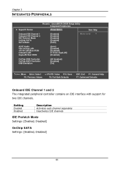
...CMOS Setup Utility Integrated Peripherals [Press Enter] Item Help Onboard IDE Channel 1 Onboard IDE Channel 2 IDE Prefetch Mode OnChip SATA SATA Mode [Enabled] [Enabled] [Enabled] [Enabled] [RAID] Menu Level AC97 Audio VIA OnChip LAN 10/100 LAN Boot ROM Onboard LAN GigaLAN Boot ROM [Auto] [Enabled] [Disabled] [VT6122 GigaLAN] [Disabled] OnChip USB Controller OnChip EHCI Controller USB Emulation [All Enabled] [Enabled] [On] : Move Enter: Select +/-/PU/PD: Value F10: Save F5: Previous Values F6: Fail-Safe Defaults ESC: Exit F1: General Help F7: Optimized Defaults Onboard IDE Channel...
...CMOS Setup Utility Integrated Peripherals [Press Enter] Item Help Onboard IDE Channel 1 Onboard IDE Channel 2 IDE Prefetch Mode OnChip SATA SATA Mode [Enabled] [Enabled] [Enabled] [Enabled] [RAID] Menu Level AC97 Audio VIA OnChip LAN 10/100 LAN Boot ROM Onboard LAN GigaLAN Boot ROM [Auto] [Enabled] [Disabled] [VT6122 GigaLAN] [Disabled] OnChip USB Controller OnChip EHCI Controller USB Emulation [All Enabled] [Enabled] [On] : Move Enter: Select +/-/PU/PD: Value F10: Save F5: Previous Values F6: Fail-Safe Defaults ESC: Exit F1: General Help F7: Optimized Defaults Onboard IDE Channel...

User Manual
Page 53
... hard disk drives Only SATA supports RAID AC'97 Audio Auto allows the mainboard to an audio device. Disable the controller if another controller card is detected Turn off onboard controller to 150MB/sec. Setting Auto Disabled Description Enables onboard controller if audio device is being used . BIOS Setup SATA Mode Serial ATA is detected, the onboard VIA AC'97 (Audio Codec'97) controller will be enabled; If the device is the latest generation of up to allow external controller VIA OnChip LAN Settings: [Enabled, Disabled] 10/100 LAN Boot ROM Settings: [Enabled, Disabled] Onboard...
... hard disk drives Only SATA supports RAID AC'97 Audio Auto allows the mainboard to an audio device. Disable the controller if another controller card is detected Turn off onboard controller to 150MB/sec. Setting Auto Disabled Description Enables onboard controller if audio device is being used . BIOS Setup SATA Mode Serial ATA is detected, the onboard VIA AC'97 (Audio Codec'97) controller will be enabled; If the device is the latest generation of up to allow external controller VIA OnChip LAN Settings: [Enabled, Disabled] 10/100 LAN Boot ROM Settings: [Enabled, Disabled] Onboard...

User Manual
Page 55
... IO DEVICE BIOS Setup Onboard Serial Port 1 Onboard Serial Port 2 UART Mode Select RxD, TxD Active IR Transmission Delay UR2 Duplex Mode Use IR Pins Phoenix - AwardBIOS CMOS Setup Utility SuperIO Device [3F8/IRQ4] [2F8/IRQ3] [Normal] [Hi,Hi] [Disabled] [Half] [IR-Rx2Tx2] Item Help Menu Level Onboard Parallel Port Parallel Port Mode EPP Mode Select ECP Mode Use DMA UART 3 UART 3 Use IRQ UART 4 UART 4 Use IRQ [378/IRQ7] [SPP] [EPP1.7] [3] [3E8] [IRQ5] [2E8] [IRQ10] : Move Enter: Select...
... IO DEVICE BIOS Setup Onboard Serial Port 1 Onboard Serial Port 2 UART Mode Select RxD, TxD Active IR Transmission Delay UR2 Duplex Mode Use IR Pins Phoenix - AwardBIOS CMOS Setup Utility SuperIO Device [3F8/IRQ4] [2F8/IRQ3] [Normal] [Hi,Hi] [Disabled] [Half] [IR-Rx2Tx2] Item Help Menu Level Onboard Parallel Port Parallel Port Mode EPP Mode Select ECP Mode Use DMA UART 3 UART 3 Use IRQ UART 4 UART 4 Use IRQ [378/IRQ7] [SPP] [EPP1.7] [3] [3E8] [IRQ5] [2E8] [IRQ10] : Move Enter: Select...
User Manual
Page 59
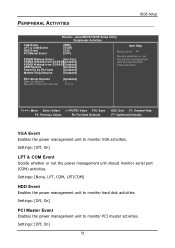
...] HDD Event Enables the power management unit to monitor PCI master activities. PERIPHERAL ACTIVITIES BIOS Setup Phoenix - Settings: [Off, On] PCI Master Event Enables the power management unit to monitor hard disk activities. RTC Alarm Resume Date (of Month) Resume Time (hh:mm:ss) [Disabled] 0 0: 0: 0 : Move Enter: Select +/-/PU/PD: Value F10: Save F5: Previous Values F6: Fail-Safe Defaults ESC: Exit F1: General Help F7: Optimized Defaults VGA Event Enables...
...] HDD Event Enables the power management unit to monitor PCI master activities. PERIPHERAL ACTIVITIES BIOS Setup Phoenix - Settings: [Off, On] PCI Master Event Enables the power management unit to monitor hard disk activities. RTC Alarm Resume Date (of Month) Resume Time (hh:mm:ss) [Disabled] 0 0: 0: 0 : Move Enter: Select +/-/PU/PD: Value F10: Save F5: Previous Values F6: Fail-Safe Defaults ESC: Exit F1: General Help F7: Optimized Defaults VGA Event Enables...

User Manual
Page 60
... any Wake-on LAN or Ring-In signals from the Ethernet or modem to restore the system from a suspended state. Chapter 3 PS2KB Wakeup Select When selecting "Password", press or to an active state. Settings: [Disabled, Enabled] 52 Settings: [Disabled, Enabled] Modem Ring Resume Enables any PCI card to power up the system or resume from a suspended state to an active state. Such PCI cards include LAN card, onboard LAN controller, onboard USB ports...
... any Wake-on LAN or Ring-In signals from the Ethernet or modem to restore the system from a suspended state. Chapter 3 PS2KB Wakeup Select When selecting "Password", press or to an active state. Settings: [Disabled, Enabled] 52 Settings: [Disabled, Enabled] Modem Ring Resume Enables any PCI card to power up the system or resume from a suspended state to an active state. Such PCI cards include LAN card, onboard LAN controller, onboard USB ports...
User Manual
Page 63
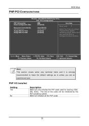
... to leave the default settings as is unless you are an experienced user. PNP OS Installed Setting Yes No Description BIOS will initialize all the PnP cards 55 AwardBIOS CMOS Setup Utility PnP / PCI Configurations PNP OS Installed Reset Configuration Data Resources Controlled By IRQ Resources Assign IRQ For VGA Assign IRQ For USB [No] [Disabled] [Auto(ESCD)] Press Enter [Enabled] [Enabled] Item Help Menu Level Select Yes if you are using a Plug and Play capable...
... to leave the default settings as is unless you are an experienced user. PNP OS Installed Setting Yes No Description BIOS will initialize all the PnP cards 55 AwardBIOS CMOS Setup Utility PnP / PCI Configurations PNP OS Installed Reset Configuration Data Resources Controlled By IRQ Resources Assign IRQ For VGA Assign IRQ For USB [No] [Disabled] [Auto(ESCD)] Press Enter [Enabled] [Enabled] Item Help Menu Level Select Yes if you are using a Plug and Play capable...
User Manual
Page 67
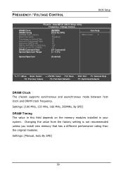
... Spectrum [Enabled] : Move Enter: Select +/-/PU/PD: Value F10: Save F5: Previous Values F6: Fail-Safe Defaults ESC: Exit F1: General Help F7: Optimized Defaults DRAM Clock The chipset supports synchronous and asynchronous mode between host clock and DRAM clock frequency. Settings: [100 MHz, 133 MHz, 166 MHz, 200MHz, By SPD] DRAM Timing The value in this field depends on the memory modules installed in your system. FREQUENCY / VOLTAGE CONTROL BIOS Setup Phoenix...
... Spectrum [Enabled] : Move Enter: Select +/-/PU/PD: Value F10: Save F5: Previous Values F6: Fail-Safe Defaults ESC: Exit F1: General Help F7: Optimized Defaults DRAM Clock The chipset supports synchronous and asynchronous mode between host clock and DRAM clock frequency. Settings: [100 MHz, 133 MHz, 166 MHz, 200MHz, By SPD] DRAM Timing The value in this field depends on the memory modules installed in your system. FREQUENCY / VOLTAGE CONTROL BIOS Setup Phoenix...
User Manual
Page 79
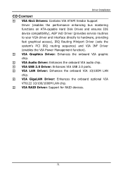
...Hard Disk Drives and ensures IDE device compatibility), AGP VxD Driver (provides service routines to your VGA driver and interface directly to hardware, providing fast graphical access), IRQ Routing Miniport Driver (sets the system's PCI IRQ routing sequence) and VIA INF Driver (enables the VIA Power Management function). VIA Audio Driver: Enhances the onboard VIA audio chip. VIA USB 2.0 Driver: Enhances VIA USB 2.0 ports. VIA LAN Driver: Enhances the onboard VIA 10/100M LAN chip. VIA RAID Driver: Support for RAID devices. 71 VIA Graphics Driver: Enhances the onboard VIA graphic chip...
...Hard Disk Drives and ensures IDE device compatibility), AGP VxD Driver (provides service routines to your VGA driver and interface directly to hardware, providing fast graphical access), IRQ Routing Miniport Driver (sets the system's PCI IRQ routing sequence) and VIA INF Driver (enables the VIA Power Management function). VIA Audio Driver: Enhances the onboard VIA audio chip. VIA USB 2.0 Driver: Enhances VIA USB 2.0 ports. VIA LAN Driver: Enhances the onboard VIA 10/100M LAN chip. VIA RAID Driver: Support for RAID devices. 71 VIA Graphics Driver: Enhances the onboard VIA graphic chip...
