
User Manual
Page 6
...ii Chapter 1 1 Specifications 1 Mainboard Specifications 2 Mainboard Layout 5 Back Panel Layout 6 Back Panel Ports 7 Slots 7 Onboard Connectors 8 Onboard Jumpers 8 Chapter 2 9 Installation 9 CPU 10 Memory Module Installation 12 Connecting the Power Supply 13 Back Panel Ports 14 Connectors 17 Jumpers 25 Slots 27 Chapter 3 29 BIOS Setup 29 Entering Setup 30 Control Keys 31 Navigating the BIOS Menus 32 Getting Help 33 Main Menu 34 Standard CMOS Features 36 IDE Drives 37 Advanced BIOS Features 38 CPU Feature 41 Hard Disk Boot Priority 44 Advanced Chipset Features 45...
...ii Chapter 1 1 Specifications 1 Mainboard Specifications 2 Mainboard Layout 5 Back Panel Layout 6 Back Panel Ports 7 Slots 7 Onboard Connectors 8 Onboard Jumpers 8 Chapter 2 9 Installation 9 CPU 10 Memory Module Installation 12 Connecting the Power Supply 13 Back Panel Ports 14 Connectors 17 Jumpers 25 Slots 27 Chapter 3 29 BIOS Setup 29 Entering Setup 30 Control Keys 31 Navigating the BIOS Menus 32 Getting Help 33 Main Menu 34 Standard CMOS Features 36 IDE Drives 37 Advanced BIOS Features 38 CPU Feature 41 Hard Disk Boot Priority 44 Advanced Chipset Features 45...

User Manual
Page 15
BACK PANEL PORTS Port Audio Jacks COM1 PS/2 Mouse PS/2 Keyboard RCA/SPDIF RJ45 USB VGA S-Video Description 3 Audio ports (line-out, line-in and mic-in) Serial port 1 PS/2 mouse port PS/2 keyboard port RCA port (SPDIF or TV out) RJ45 port USB 2.0 ports VGA port S-Video port SLOTS Port DDR DIMM PCI Description Memory module slot Expansion card slot Specifications Page 13-15 13 13 13 13-14 13-14 13-14 13 13-14 Page 11 26 7
BACK PANEL PORTS Port Audio Jacks COM1 PS/2 Mouse PS/2 Keyboard RCA/SPDIF RJ45 USB VGA S-Video Description 3 Audio ports (line-out, line-in and mic-in) Serial port 1 PS/2 mouse port PS/2 keyboard port RCA port (SPDIF or TV out) RJ45 port USB 2.0 ports VGA port S-Video port SLOTS Port DDR DIMM PCI Description Memory module slot Expansion card slot Specifications Page 13-15 13 13 13 13-14 13-14 13-14 13 13-14 Page 11 26 7

User Manual
Page 16
.../DVI SATA 1-2 SPDIF 1-2 SMBus SYSFAN USB 5-6 TV Description IEEE 1394 connector Power cable connector COM port 2 connector CPU fan connector Fast Infrared Radiation connector Front Audio connector Front panel connector IDE drive connectors Keyboard and Mouse connector LPC/SIR connector LVDS/TTL/DVI connector Serial ATA 1 and 2 connectors SPDIF In/Out connectors SMBus connector System fan connector Universal Serial Bus 2.0 connectors 3-4 TV output connector ONBOARD JUMPERS Jumper CLEAR_CMOS PANEL SPDIF_SEL WP Description Reset CMOS settings IDE selector S/PDIF selector BIOS write protection...
.../DVI SATA 1-2 SPDIF 1-2 SMBus SYSFAN USB 5-6 TV Description IEEE 1394 connector Power cable connector COM port 2 connector CPU fan connector Fast Infrared Radiation connector Front Audio connector Front panel connector IDE drive connectors Keyboard and Mouse connector LPC/SIR connector LVDS/TTL/DVI connector Serial ATA 1 and 2 connectors SPDIF In/Out connectors SMBus connector System fan connector Universal Serial Bus 2.0 connectors 3-4 TV output connector ONBOARD JUMPERS Jumper CLEAR_CMOS PANEL SPDIF_SEL WP Description Reset CMOS settings IDE selector S/PDIF selector BIOS write protection...

User Manual
Page 23
RCA / SPDIF jack The yellow jack connects to a Local Area Network (LAN) through a network hub and USB 2.0 devices. These ports allow connection to external composite video device or audio output device. S-Video port The black port allows you to connect TV monitor or Svideo device to the mainboard. Installation 15 USB 2.0 ports These two 4-pin Universal Serial Bus (USB) ports are available for connecting USB 2.0 devices. RJ45 10/100 LAN and USB Connector The mainboard provides a standard RJ-45 and USB 2.0 ports.
RCA / SPDIF jack The yellow jack connects to a Local Area Network (LAN) through a network hub and USB 2.0 devices. These ports allow connection to external composite video device or audio output device. S-Video port The black port allows you to connect TV monitor or Svideo device to the mainboard. Installation 15 USB 2.0 ports These two 4-pin Universal Serial Bus (USB) ports are available for connecting USB 2.0 devices. RJ45 10/100 LAN and USB Connector The mainboard provides a standard RJ-45 and USB 2.0 ports.
User Manual
Page 24
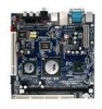
..., etc. Note: The audio ports can enable the function by clicking the "Vinyl Audio" icon on the back panel. You can be switched to setup the 6-channel system. The Line-In jack is for connecting to a microphone. The Mic jack is for connecting to the 3-jack connectors on your desktop after installing the audio driver. After completing the previous installation, connect the speakers to external speakers or headphones. Jack...
..., etc. Note: The audio ports can enable the function by clicking the "Vinyl Audio" icon on the back panel. You can be switched to setup the 6-channel system. The Line-In jack is for connecting to a microphone. The Mic jack is for connecting to the 3-jack connectors on your desktop after installing the audio driver. After completing the previous installation, connect the speakers to external speakers or headphones. Jack...

User Manual
Page 33
... jumper is off. Avoid clearing the CMOS while the system is on pins 2 and 3 while the system is for setting some mainboard functions. Installation JUMPERS The mainboard provides jumpers for selecting between SPDIF and RCA (composite) video. 24 Setting 1 2 3 4 RCA Composite ON ON OFF OFF SPDIF OFF OFF ON ON RCA 13 24 SPDIF 13 25 Clear CMOS: CLEAR_CMOS The onboard CMOS RAM stores system configuration data and has an onboard battery power supply. Setting the jumper...
... jumper is off. Avoid clearing the CMOS while the system is on pins 2 and 3 while the system is for setting some mainboard functions. Installation JUMPERS The mainboard provides jumpers for selecting between SPDIF and RCA (composite) video. 24 Setting 1 2 3 4 RCA Composite ON ON OFF OFF SPDIF OFF OFF ON ON RCA 13 24 SPDIF 13 25 Clear CMOS: CLEAR_CMOS The onboard CMOS RAM stores system configuration data and has an onboard battery power supply. Setting the jumper...

User Manual
Page 45
... location of the landing zone Number of your hard disk vendor or system manufacturer. The hard disk will not work properly if you select "Manual", make sure the information is a table that details required hard drive information when using the "Manual" mode. AwardBIOS CMOS Setup Utility IDE Channel 0 Master [Press Enter] Item Help [Auto] [Auto] 0 MB Menu Level To auto-detect the HDD's size, head... Below is from your drive must match with the drive table. Setting IDE Channel Access Mode...
... location of the landing zone Number of your hard disk vendor or system manufacturer. The hard disk will not work properly if you select "Manual", make sure the information is a table that details required hard drive information when using the "Manual" mode. AwardBIOS CMOS Setup Utility IDE Channel 0 Master [Press Enter] Item Help [Auto] [Auto] 0 MB Menu Level To auto-detect the HDD's size, head... Below is from your drive must match with the drive table. Setting IDE Channel Access Mode...

User Manual
Page 46
...AwardBIOS CMOS Setup Utility Advanced BIOS Features CPU Feature Hard Disk Boot Priority Virus Warning CPU L1 & L2 Cache Quick Power On Self Test First Boot Device Second Boot Device Third Boot Device Boot Other Device Boot Up NumLock Status Typematic Rate Setting Typematic Rate (Chars/Sec) Typematic Delay (Msec) Security Option APIC Mode MPS Version Control for OS Display Full Screen Logo Display Small Logo [Press Enter] [Press Enter] [Disabled] [Enabled] [Enabled] [USB-FDD] [CDROM] [Hard Disk] [Enabled] [On] [Disabled] 6 250 [Setup] [Enabled] [1.4] [Enabled] [Disabled] Item Help Menu Level...
...AwardBIOS CMOS Setup Utility Advanced BIOS Features CPU Feature Hard Disk Boot Priority Virus Warning CPU L1 & L2 Cache Quick Power On Self Test First Boot Device Second Boot Device Third Boot Device Boot Other Device Boot Up NumLock Status Typematic Rate Setting Typematic Rate (Chars/Sec) Typematic Delay (Msec) Security Option APIC Mode MPS Version Control for OS Display Full Screen Logo Display Small Logo [Press Enter] [Press Enter] [Disabled] [Enabled] [Enabled] [USB-FDD] [CDROM] [Hard Disk] [Enabled] [On] [Disabled] 6 250 [Setup] [Enabled] [1.4] [Enabled] [Disabled] Item Help Menu Level...

User Manual
Page 47
... 10-key Forces keypad to boot from the "First/Second/Third Boot Device" list. Setting LS120 Hard Disk CD-ROM ZIP100 USB-FDD USB-ZIP USB-CDROM Legacy LAN Disabled Description Boot from LS-120 drive Boot from the HDD Boot from CD-ROM Boot from ATAPI ZIP drive Boot from USB floppy drive Boot from USB ZIP drive Boot from USB CDROM Boot from network drive Disable the boot device sequence Boot Other Device Enables the system to boot from alternate devices if the system fails to behave as BIOS attempts to load the disk...
... 10-key Forces keypad to boot from the "First/Second/Third Boot Device" list. Setting LS120 Hard Disk CD-ROM ZIP100 USB-FDD USB-ZIP USB-CDROM Legacy LAN Disabled Description Boot from LS-120 drive Boot from the HDD Boot from CD-ROM Boot from ATAPI ZIP drive Boot from USB floppy drive Boot from USB ZIP drive Boot from USB CDROM Boot from network drive Disable the boot device sequence Boot Other Device Enables the system to boot from alternate devices if the system fails to behave as BIOS attempts to load the disk...

User Manual
Page 48
... to run BIOS Setup APIC Mode Enables APIC (Advanced Programmable Interrupt Controller) functionality. Settings: [Enabled, Disabled] MPS Variation Control for OS Settings: [1.1, 1.4] Display Full Screen Logo Show full screen logo during BIOS boot up process. Chapter 3 Typematic Rate (Chars/Sec) This item sets the rate (characters/second) at which the system retrieves a signal from the depressed key. Settings: [250, 500, 750, 1000] Security Option Selects whether the password is powered on...
... to run BIOS Setup APIC Mode Enables APIC (Advanced Programmable Interrupt Controller) functionality. Settings: [Enabled, Disabled] MPS Variation Control for OS Settings: [1.1, 1.4] Display Full Screen Logo Show full screen logo during BIOS boot up process. Chapter 3 Typematic Rate (Chars/Sec) This item sets the rate (characters/second) at which the system retrieves a signal from the depressed key. Settings: [250, 500, 750, 1000] Security Option Selects whether the password is powered on...

User Manual
Page 53
... CMOS Setup Utility Advanced Chipset Features Display Card Priority AGP & P2P Bridge Control CPU & PCI Bus Control AGP Driving Control AGP Driving Value Select Display Device Panel Type HDTV Display HDTV Type HDTV Input Mode TV H/W Layout TV Type TV Output Connector [PCI Slot] [Press Enter] [Press Enter] [Auto] DA [CRT] [07] Disabled HDTV 720P RGB Input [Default] [NTSC] [Press Enter] Item Help Menu Level If there are familiar with the system. Display Card Priority This setting specifies which one to the type of display being used to signal driving...
... CMOS Setup Utility Advanced Chipset Features Display Card Priority AGP & P2P Bridge Control CPU & PCI Bus Control AGP Driving Control AGP Driving Value Select Display Device Panel Type HDTV Display HDTV Type HDTV Input Mode TV H/W Layout TV Type TV Output Connector [PCI Slot] [Press Enter] [Press Enter] [Auto] DA [CRT] [07] Disabled HDTV 720P RGB Input [Default] [NTSC] [Press Enter] Item Help Menu Level If there are familiar with the system. Display Card Priority This setting specifies which one to the type of display being used to signal driving...

User Manual
Page 56
... plug in the AGP 4x card. Settings: [Enabled, Disabled] 48 Host cycles that hit the aperture range are forwarded to graphics memory address space. The aperture is used , it can transfer video data at 1066MB/s. AwardBIOS CMOS Setup Utility AGP & P2P Bridge Control AGP Aperture Size AGP 2.0 Mode AGP Fast Write AGP 3.0 Calibration Cycle VGA Share Memory Size Direct Frame Buffer Size [128M] [4x] [Disabled] [Enabled] [64M] [Enabled] Item Help Menu Level : Move Enter...
... plug in the AGP 4x card. Settings: [Enabled, Disabled] 48 Host cycles that hit the aperture range are forwarded to graphics memory address space. The aperture is used , it can transfer video data at 1066MB/s. AwardBIOS CMOS Setup Utility AGP & P2P Bridge Control AGP Aperture Size AGP 2.0 Mode AGP Fast Write AGP 3.0 Calibration Cycle VGA Share Memory Size Direct Frame Buffer Size [128M] [4x] [Disabled] [Enabled] [64M] [Enabled] Item Help Menu Level : Move Enter...

User Manual
Page 60
... IDE channels IDE Prefetch Mode Settings: [Enabled, Disabled] IDE HDD Block Mode This allows the hard disk controller to use the fast block mode to transfer data to and from the hard disk drive. Block mode is also called block transfer, multiple commands or multiple sector read / write. AwardBIOS CMOS Setup Utility Integrated Peripherals [Press Enter] Item Help [Enabled] [Enabled] [Enabled] [Enabled] [Enabled] [RAID] Menu Level [Auto] [All Enabled] [Enabled] [On] [Disabled] : Move Enter: Select F5: Previous Values +/-/PU/PD: Value F10: Save F6: Fail-Safe Defaults...
... IDE channels IDE Prefetch Mode Settings: [Enabled, Disabled] IDE HDD Block Mode This allows the hard disk controller to use the fast block mode to transfer data to and from the hard disk drive. Block mode is also called block transfer, multiple commands or multiple sector read / write. AwardBIOS CMOS Setup Utility Integrated Peripherals [Press Enter] Item Help [Enabled] [Enabled] [Enabled] [Enabled] [Enabled] [RAID] Menu Level [Auto] [All Enabled] [Enabled] [On] [Disabled] : Move Enter: Select F5: Previous Values +/-/PU/PD: Value F10: Save F6: Fail-Safe Defaults...

User Manual
Page 61
... hard disk drives Only SATA supports RAID AC'97 Audio Auto allows the mainboard to "KB/MS", support USB legacy keyboard and mouse, no support USB storage. When set to detect whether an audio device is used to connect to 150MB/sec. BIOS Setup OnChip SATA Settings: [Enabled, Disabled] SATA Mode Serial ATA is the latest generation of up to an audio device. otherwise, it is detected Turn off onboard controller to allow external controller OnChip USB Controller Settings: [All Disabled, All Enabled, 1&2 USB Port, 2&3 USB Port, 1&3 USB Port, 1 USB Port, 2 USB Port, 3 USB Port] OnChip...
... hard disk drives Only SATA supports RAID AC'97 Audio Auto allows the mainboard to "KB/MS", support USB legacy keyboard and mouse, no support USB storage. When set to detect whether an audio device is used to connect to 150MB/sec. BIOS Setup OnChip SATA Settings: [Enabled, Disabled] SATA Mode Serial ATA is the latest generation of up to an audio device. otherwise, it is detected Turn off onboard controller to allow external controller OnChip USB Controller Settings: [All Disabled, All Enabled, 1&2 USB Port, 2&3 USB Port, 1&3 USB Port, 1 USB Port, 2 USB Port, 3 USB Port] OnChip...

User Manual
Page 66
... should monitor serial port (COM) activities. Settings: [Disabled, Enabled] VGA Event Enables the power management unit to monitor hard disk activities. Settings: [None, COM] HDD Event Enables the power management unit to monitor VGA activities. Settings: [Off, On] PowerOn by PCI Card Enables activity detected from any Wake-on LAN or Ring-In signals from the Ethernet or modem to restore the system from a suspended state to monitor PCI master activities. Such PCI cards include LAN card, onboard LAN controller, onboard USB ports, etc. Chapter 3 USB Resume...
... should monitor serial port (COM) activities. Settings: [Disabled, Enabled] VGA Event Enables the power management unit to monitor hard disk activities. Settings: [None, COM] HDD Event Enables the power management unit to monitor VGA activities. Settings: [Off, On] PowerOn by PCI Card Enables activity detected from any Wake-on LAN or Ring-In signals from the Ethernet or modem to restore the system from a suspended state to monitor PCI master activities. Such PCI cards include LAN card, onboard LAN controller, onboard USB ports, etc. Chapter 3 USB Resume...

User Manual
Page 73
... PCI Clk [By SPD] [Auto By SPD] 2.5/ 4 Disabled 4T 07T 4T 25T 3T [2T] [1T/2T] [4T] [2T Command] [Auto] 03 [Enabled] Item Help Menu Level Spread Spectrum [0.25%] : Move Enter: Select F5: Previous Values +/-/PU/PD: Value F10: Save F6: Fail-Safe Defaults ESC: Exit F1: General F7: Optimized Defaults Help DRAM Clock The chipset supports synchronous and asynchronous mode between host clock and DRAM clock frequency. AwardBIOS CMOS Setup Utility Frequency / Voltage Control DRAM Clock DRAM...
... PCI Clk [By SPD] [Auto By SPD] 2.5/ 4 Disabled 4T 07T 4T 25T 3T [2T] [1T/2T] [4T] [2T Command] [Auto] 03 [Enabled] Item Help Menu Level Spread Spectrum [0.25%] : Move Enter: Select F5: Previous Values +/-/PU/PD: Value F10: Save F6: Fail-Safe Defaults ESC: Exit F1: General F7: Optimized Defaults Help DRAM Clock The chipset supports synchronous and asynchronous mode between host clock and DRAM clock frequency. AwardBIOS CMOS Setup Utility Frequency / Voltage Control DRAM Clock DRAM...

User Manual
Page 85
Note: D: might not be the drive letter of the CD-ROM/DVD-ROM in your system. 77 The driver utilities and software menu screen should run automatically, click on the screen. If the CD does not run automatically after closing the CD-ROM or DVD-ROM drive. Then type: "D:\Setup.exe". Driver Installation Running the Driver Utilities CD To start using the CD, insert the CD into the CD-ROM or DVD-ROM drive. The CD should then appear on the "Start" button and select "Run..."
Note: D: might not be the drive letter of the CD-ROM/DVD-ROM in your system. 77 The driver utilities and software menu screen should run automatically, click on the screen. If the CD does not run automatically after closing the CD-ROM or DVD-ROM drive. Then type: "D:\Setup.exe". Driver Installation Running the Driver Utilities CD To start using the CD, insert the CD into the CD-ROM or DVD-ROM drive. The CD should then appear on the "Start" button and select "Run..."

User Manual
Page 86
... VIA 10/100M LAN chip. VIA GLAN Driver: Enhances the onboard VIA Giga LAN chip. Chapter 4 CD CONTENT VIA 4in1 Drivers: Contains VIA ATAPI Vendor Support Driver (enables the performance enhancing bus mastering functions on ATA-capable Hard Disk Drives and ensures IDE device compatibility), AGP VxD Driver (provides service routines to your VGA driver and interface directly to hardware, providing fast graphical access), IRQ Routing Miniport Driver (sets the system's PCI IRQ routing sequence) and VIA INF Driver (enables the VIA Power Management function). VIA RAID Driver: Support for SATA RAID...
... VIA 10/100M LAN chip. VIA GLAN Driver: Enhances the onboard VIA Giga LAN chip. Chapter 4 CD CONTENT VIA 4in1 Drivers: Contains VIA ATAPI Vendor Support Driver (enables the performance enhancing bus mastering functions on ATA-capable Hard Disk Drives and ensures IDE device compatibility), AGP VxD Driver (provides service routines to your VGA driver and interface directly to hardware, providing fast graphical access), IRQ Routing Miniport Driver (sets the system's PCI IRQ routing sequence) and VIA INF Driver (enables the VIA Power Management function). VIA RAID Driver: Support for SATA RAID...

Operation Guide
Page 3
... applications. EPIA EN-Series Operating Guide VIA EPIA EN-Series Overview The VIA EPIA EN-Series Mini-ITX Mainboard is based on the VIA CN700 chipset featuring an embedded hardware MPEG-2 accelerator and integrated VIA UniChrome™ Pro 2D/3D graphics for rich digital media performance. The VIA EPIA EN-Series is supported with a full range of Mini-ITX chassis as well as a COM port and has one PCI slot for small, low power and secure x86 processor platforms...
... applications. EPIA EN-Series Operating Guide VIA EPIA EN-Series Overview The VIA EPIA EN-Series Mini-ITX Mainboard is based on the VIA CN700 chipset featuring an embedded hardware MPEG-2 accelerator and integrated VIA UniChrome™ Pro 2D/3D graphics for rich digital media performance. The VIA EPIA EN-Series is supported with a full range of Mini-ITX chassis as well as a COM port and has one PCI slot for small, low power and secure x86 processor platforms...
Operation Guide
Page 5
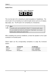
... EN-Series Operating Guide VIA EPIA EN-Series Specifications Model Name EPIA EN15000 EPIA EN12000E Processor VIA C7 1.5GHz NanoBGA2 VIA Eden 1.2GHz NanoBGA2 Chipset - Up to change without prior notice. CPU temperature reading, CPU voltage monitoring - VIA CN700 North Bridge - Mini-ITX (6-layer) - 17 cm x 17 cm * The specification is required) - 1 Front-Panel pin header - 1 ATX Power Connector Back Panel I/O - 1 PS2 Mouse port - 1 PS2 Keyboard port - 1 RJ-45 LAN port - 1 Serial port - 4 USB 2.0 ports - 1 VGA port - 1 RCA port (S/PDIF or TV out) - 1 S-Video port - 3 Audio...
... EN-Series Operating Guide VIA EPIA EN-Series Specifications Model Name EPIA EN15000 EPIA EN12000E Processor VIA C7 1.5GHz NanoBGA2 VIA Eden 1.2GHz NanoBGA2 Chipset - Up to change without prior notice. CPU temperature reading, CPU voltage monitoring - VIA CN700 North Bridge - Mini-ITX (6-layer) - 17 cm x 17 cm * The specification is required) - 1 Front-Panel pin header - 1 ATX Power Connector Back Panel I/O - 1 PS2 Mouse port - 1 PS2 Keyboard port - 1 RJ-45 LAN port - 1 Serial port - 4 USB 2.0 ports - 1 VGA port - 1 RCA port (S/PDIF or TV out) - 1 S-Video port - 3 Audio...
