User Manual
Page 6
... Back Panel Ports 1-5 Slots 1-5 Onboard Connectors and Jumpers 1-6 Chapter 2: Installation 2-1 CPU Installation 2-2 Memory Module Installation 2-4 Connecting the Power Supply 2-6 Back Panel Ports 2-7 Connectors 2-11 Jumpers 2-19 Slots 2-20 Chapter 3: BIOS Setup 3-1 Entering Setup 3-2 Control Keys 3-2 Gettings ...3-3 The Main Menu 3-4 Standard CMOS Features 3-6 Advanced BIOS Features 3-8 Advanced Chipset Features 3-12 Integrated Peripherals 3-14 Power Management Setup 3-18 PNP / PCI Configurations 3-23 PC Health Status 3-26 Frequency / Voltage Control 3-27 Load Fail...
... Back Panel Ports 1-5 Slots 1-5 Onboard Connectors and Jumpers 1-6 Chapter 2: Installation 2-1 CPU Installation 2-2 Memory Module Installation 2-4 Connecting the Power Supply 2-6 Back Panel Ports 2-7 Connectors 2-11 Jumpers 2-19 Slots 2-20 Chapter 3: BIOS Setup 3-1 Entering Setup 3-2 Control Keys 3-2 Gettings ...3-3 The Main Menu 3-4 Standard CMOS Features 3-6 Advanced BIOS Features 3-8 Advanced Chipset Features 3-12 Integrated Peripherals 3-14 Power Management Setup 3-18 PNP / PCI Configurations 3-23 PC Health Status 3-26 Frequency / Voltage Control 3-27 Load Fail...

User Manual
Page 14
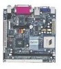
... damage some components. Some components may be damaged if they are installed incorrectly. This chapter includes the following sections: CPU Memory Module Installation Connecting the Power Supply Back Panel Ports Connectors Jumpers Slots 2-2 2-4 2-6 2-7 2-11 2-19 2-20 2-1 While installing the mainboard, carefully hold the components and closely follow the installation procedures. Chapter 2 Installation...
... damage some components. Some components may be damaged if they are installed incorrectly. This chapter includes the following sections: CPU Memory Module Installation Connecting the Power Supply Back Panel Ports Connectors Jumpers Slots 2-2 2-4 2-6 2-7 2-11 2-19 2-20 2-1 While installing the mainboard, carefully hold the components and closely follow the installation procedures. Chapter 2 Installation...

User Manual
Page 19
... inserted in the proper orientation and the pins are installed correctly to be caused. ATX 20-Pin Power Connector To connect the ATX power supply, make sure that no damage will be connected. Then, push down the power supply plug firmly into the connector. Pin Signal 1 3.3V 1 10 2 3.3V 3 GND 4 5V 11 20 5 GND 6 5V... 10 12V 11 3.3V 12 -12V 13 GND 14 PS_ON 15 GND 16 GND 17 GND 18 NC 19 5V 20 5V 2-6 Chapter 2 Connecting the Power Supply The VIA EPIA-M Mini-ITX Mainboard requires an ATX power supply to ensure that all components are correctly aligned.
... inserted in the proper orientation and the pins are installed correctly to be caused. ATX 20-Pin Power Connector To connect the ATX power supply, make sure that no damage will be connected. Then, push down the power supply plug firmly into the connector. Pin Signal 1 3.3V 1 10 2 3.3V 3 GND 4 5V 11 20 5 GND 6 5V... 10 12V 11 3.3V 12 -12V 13 GND 14 PS_ON 15 GND 16 GND 17 GND 18 NC 19 5V 20 5V 2-6 Chapter 2 Connecting the Power Supply The VIA EPIA-M Mini-ITX Mainboard requires an ATX power supply to ensure that all components are correctly aligned.

User Manual
Page 32
... 1 ON OFF 2 ON OFF 3 OFF ON 4 OFF ON 2-19 Clear CMOS: CLEAR_CMOS The onboard CMOS RAM stores system configuration data and has an onboard battery power supply. For SPDIF, please short pins 1 and 2. You can select either RCA Video or S/PDIF as the enabled function on will explain how to change settings...
... 1 ON OFF 2 ON OFF 3 OFF ON 4 OFF ON 2-19 Clear CMOS: CLEAR_CMOS The onboard CMOS RAM stores system configuration data and has an onboard battery power supply. For SPDIF, please short pins 1 and 2. You can select either RCA Video or S/PDIF as the enabled function on will explain how to change settings...

User Manual
Page 33
... the PCI bus INT A# ~ INT D# pins as jumpers, switches or BIOS configuration. Chapter 2 Slots Peripheral Component Interconnect: PCI The PCI slot allows you unplug the power supply first. When adding or removing expansion cards, make sure that you to make any necessary hardware or software settings for the expansion card, such as...
... the PCI bus INT A# ~ INT D# pins as jumpers, switches or BIOS configuration. Chapter 2 Slots Peripheral Component Interconnect: PCI The PCI slot allows you unplug the power supply first. When adding or removing expansion cards, make sure that you to make any necessary hardware or software settings for the expansion card, such as...

User Manual
Page 51
In this state, power is supplied only to select S1 or S3. 3-18 In this state, no system context (CPU or chipset) is ACPI-aware (i.e. Depends on OS to essential components ... saved to most effectively save energy while operating in a manner consistent with your operating system is lost and hardware maintains all system context. Chapter 3 Power Management Setup The Power Management Setup menu configures the system to main memory, and context is restored from the memory when a "wakeup" event occurs. If your own...
In this state, power is supplied only to select S1 or S3. 3-18 In this state, no system context (CPU or chipset) is ACPI-aware (i.e. Depends on OS to essential components ... saved to most effectively save energy while operating in a manner consistent with your operating system is lost and hardware maintains all system context. Chapter 3 Power Management Setup The Power Management Setup menu configures the system to main memory, and context is restored from the memory when a "wakeup" event occurs. If your own...