User Manual
Page 9
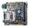
... industry-wide total connectivity initiative. as part of FlexATX mainboard form factor. The mainboard comes with an embedded VIA Processor, boasting ultra low power consumption and cool, quiet operation. 1 CHAPTER 1 Specifications The ultra-compact and highly integrated VIA EPIA-MII Mini-ITX Mainboard is the smallest form factor mainboard specification available today, developed by...
... industry-wide total connectivity initiative. as part of FlexATX mainboard form factor. The mainboard comes with an embedded VIA Processor, boasting ultra low power consumption and cool, quiet operation. 1 CHAPTER 1 Specifications The ultra-compact and highly integrated VIA EPIA-MII Mini-ITX Mainboard is the smallest form factor mainboard specification available today, developed by...
User Manual
Page 18
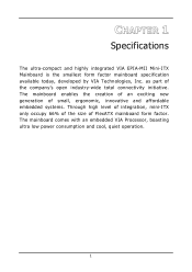
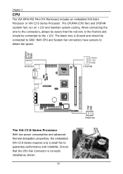
Chapter 2 CPU The VIA EPIA-MII Mini-ITX Mainboard includes an embedded VIA Eden Processor or VIA C3 E-Series Processor. Both CPU and System fan connectors have sensors to guarantee performance and reliability. When connecting the wire to the connectors, always be ... black wire is the Positive and should be connected to GND. SYSFAN Sensor +12V GND CPUFAN CLE266 The VIA C3 E-Series Processor With low power consumption and advanced thermal dissipation properties, the embedded VIA C3 E-Series requires only a small fan to detect fan speed. Ensure that the red wire is Ground and...
Chapter 2 CPU The VIA EPIA-MII Mini-ITX Mainboard includes an embedded VIA Eden Processor or VIA C3 E-Series Processor. Both CPU and System fan connectors have sensors to guarantee performance and reliability. When connecting the wire to the connectors, always be ... black wire is the Positive and should be connected to GND. SYSFAN Sensor +12V GND CPUFAN CLE266 The VIA C3 E-Series Processor With low power consumption and advanced thermal dissipation properties, the embedded VIA C3 E-Series requires only a small fan to detect fan speed. Ensure that the red wire is Ground and...
User Manual
Page 20
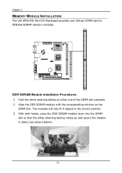
The modules will only fit if placed in place (see picture below). 12 With both hands, press the DDR SDRAM module down into the DIMM slot so that the white retaining latches rotate up and secure the module in the correct position. 3. Align the DDR SDRAM module with the corresponding notches on the DIMM slot. CLE266 DDR SDRAM Module Installation Procedures 1. Push the white retaining latches at either end of the DIMM slot outwards. 2. Chapter 2 MEMORY MODULE INSTALLATION The VIA EPIA-MII Mini-ITX Mainboard provides one 184-pin DIMM slot for DDR266 SDRAM memory modules.
The modules will only fit if placed in place (see picture below). 12 With both hands, press the DDR SDRAM module down into the DIMM slot so that the white retaining latches rotate up and secure the module in the correct position. 3. Align the DDR SDRAM module with the corresponding notches on the DIMM slot. CLE266 DDR SDRAM Module Installation Procedures 1. Push the white retaining latches at either end of the DIMM slot outwards. 2. Chapter 2 MEMORY MODULE INSTALLATION The VIA EPIA-MII Mini-ITX Mainboard provides one 184-pin DIMM slot for DDR266 SDRAM memory modules.
User Manual
Page 22
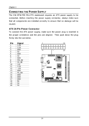
... 14 PS_ON 15 GND 16 GND 17 GND 18 NC 19 5V 20 5V 1 10 11 20 CLE266 14 Chapter 2 CONNECTING THE POWER SUPPLY The VIA EPIA-MII Mini-ITX mainboard requires an ATX power supply to ensure that all components are aligned.
... 14 PS_ON 15 GND 16 GND 17 GND 18 NC 19 5V 20 5V 1 10 11 20 CLE266 14 Chapter 2 CONNECTING THE POWER SUPPLY The VIA EPIA-MII Mini-ITX mainboard requires an ATX power supply to ensure that all components are aligned.
